
Exploring the potential of iron powder as fuel on the design and performance of container ships
Abstract
This article examines the potential implications of using iron powder as an alternative fuel on the design and performance of container ships. Iron powder is a relatively new alternative energy carrier and one in which little research has been done into the application on-board vessels as part of the maritime energy transition. The key benefits of iron powder are that it is a circular energy carrier and the combustion process emits no greenhouse gases. Transitioning to iron powder is expected to have far reaching implications for the design and performance of ships. Thus, this paper aims to perform the first study assessing the potential of this concept applied to container ships. To do so, a preliminary design space was explored with a custom parametric design model developed to generate preliminary designs of iron fuelled container ships as a function of the operational profile. Using this parametric design model, it was identified that iron fuelled container ships are weight limited, unlike conventionally fuelled container vessels. Furthermore, iron fuelled container ships are best suited for short voyages at low cruising speed. For these voyages, it was concluded that iron fuelled ships are economically feasible; however, other alternative marine fuels are likely more profitable than iron due to the low efficiency of iron fuelled ships and the high cost of iron per unit energy.
1.Introduction
The maritime sector is under increasing pressure to reduce its environmental impact. Due to the combustion of low grade fossil fuels, ships emit significant amounts of greenhouse gasses (GHGs) and air pollutants. The shipping industry is responsible for approximately 2.9% of the total anthropogenic emissions of GHGs [10], and in order to reduce the contribution of the shipping industry to anthropogenic climate change, the International Maritime Organisation (IMO) aims to reduce the emission of GHGs by at least 50% in 2050 compared to 2008 emission levels. Beyond GHGs, the IMO has also developed measures to reduce the emission of air pollutants, such as
Although the carbon intensity of ships is steadily decreasing, the demand for seaborne trade has continually increased [10]. Thus, the total emission of GHGs from the shipping industry has increased with respect to emissions in 2012, despite the implemented measures to reduce these emissions. If no additional policies are taken that reduce carbon intensity, the projected emission of GHGs from shipping in 2050 is expected to increase 90–130% compared to 2008 levels [10]. Given the emission targets of the IMO, it is likely that additional measures to reduce the emission of GHGs and air pollutants will follow [13].
One of the most promising ways to reduce the environmental impact of shipping is to use alternative marine fuels, as mentioned in the long term solutions of the IMO initial GHG strategy [14] and other literature [1,4,8]. Multiple different alternative fuels are available for the shipping industry, such as low carbon fuels like liquefied natural gas or carbon free fuels such as hydrogen or ammonia. The choice for a single alternative fuel is not straightforward, as illustrated in a review on the differences between alternative fuels [23]. Most fuels are less energy dense compared to conventional fuels or require specialised equipment to keep the fuel stored at specific conditions. The land-based infrastructure is often under-developed compared to conventional fuel infrastructure and prices are unpredictable and generally higher than conventional fuels. It is no surprise, then, that the shipping industry currently relies on conventional fuels for the vast majority of its energy needs. However, as the regulations on shipping emissions become more strict, shipowners are driven towards alternative fuels, and their importance will likely grow.
Recently, iron powder has been proposed as another potential marine fuel [17]. The potential of iron powder as an energy carrier caught public interest after a set of review papers on the use of metal powder as energy storage [2,3]. Iron powder combusts without emission of
Iron powder can be combusted, and the combustion heat is then converted to mechanical power in a heat engine. Upon combustion, the iron powder is converted to iron oxide powder, which can then be filtered out of the exhaust stream, and stored on board. Later, this oxide powder can be reformed to iron powder using renewably produced hydrogen in land-based facilities. This makes iron powder a potential cyclic energy carrier for renewable energy [2,17]. Though very little research exists on iron as a marine fuel, it has some promising properties. The volumetric energy density of iron is quite high compared to other traditional and alternative energy carriers. In addition, iron is easy and safe to store on board [17]. However, as shown in Fig. 1, iron powder has lower gravimetric energy density, potentially leading to weight or displacement issues from a ship design perspective. Given these unique characteristics, it is expected that transitioning to iron powder will have considerable implications for both the design and performance of ships. Furthermore the global supply of iron and the potential sustainable recycling process for its production in combination with the mild behaviour in terms of hazards [17], provides justification for iron in favor of the other metals listed in Fig. 1.
![Comparison of volumetric and gravimetric energy density of the alternative fuels [17].](https://content.iospress.com:443/media/isp/2023/70-1/isp-70-1-isp220012/isp-70-isp220012-g001.jpg)
To establish whether iron should be considered as a viable alternative marine fuel, this papers aims to perform the first study assessing the potential of this concept by evaluating the ship design and performance implications of an iron fuelled power plant for container ships. Container ships are generally volume limited vessels, so it is argued that a heavy but dense fuel affects the cargo carrying capacity of a container ship less than for deadweight limited vessels. Iron fuelled ships that require a large energy carrying capacity are limited in their cargo carrying capacity, since a large proportion of the available deadweight is spent on fuel. Therefore, it is argued that iron is likely more suitable for short voyages rather than ocean going vessels. Thus, the focus of this paper is on short sea shipping container ships.
2.Methods
As iron powder as fuel is expected to have far reaching implications for the ship design, an understanding of these implications is necessary to assess the final feasibility of this alternative energy concept. Technical feasibility was assessed based on naval architecture requirements related to resistance and propulsion matching, weight, stability, and cargo carrying capacity (Sections 2.3 to 2.5). In this research, data was generated on the design and performance of iron fuelled ships for different operational profiles using a custom parametric design model. This model was developed to quickly generate a range of preliminary designs for iron fuelled ships as a function of the operational profile parameters. The goal of this model was not ship design optimization explicitly, but instead to be used to help generate and explore promising design trends that can be identified within the design space of iron fuelled ships. With the data generated from the design model, economically viable operational profiles were identified based on criteria related to net present value, minimum freight rate, and required capital investment (Section 2.6). The performance of iron fuelled ships was then compared to that of ships that are fuelled with different alternative fuels.
2.1.Architecture of the parametric design model
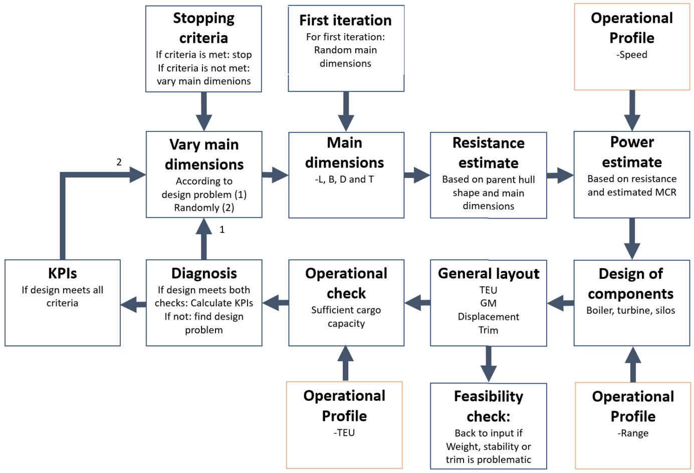
The parametric design model (Fig. 2) generates a set of preliminary designs. This way the design space of iron fuelled ships can be explored as a function of the desired operational profile defined by the speed, required cargo capacity, and range. These operational profiles are called design problems in this paper (see Section 3.1). For feasible designs, the model calculates key performance indicators (KPIs) used to rank the different designs. The KPIs are related to the economic performance of the vessel as well as its energy efficiency, and are explained in detail in Section 2.6.
Fig. 2.
Flowchart of the parametric design model.
Algorithm 1
Pseudocode of the parametric design model
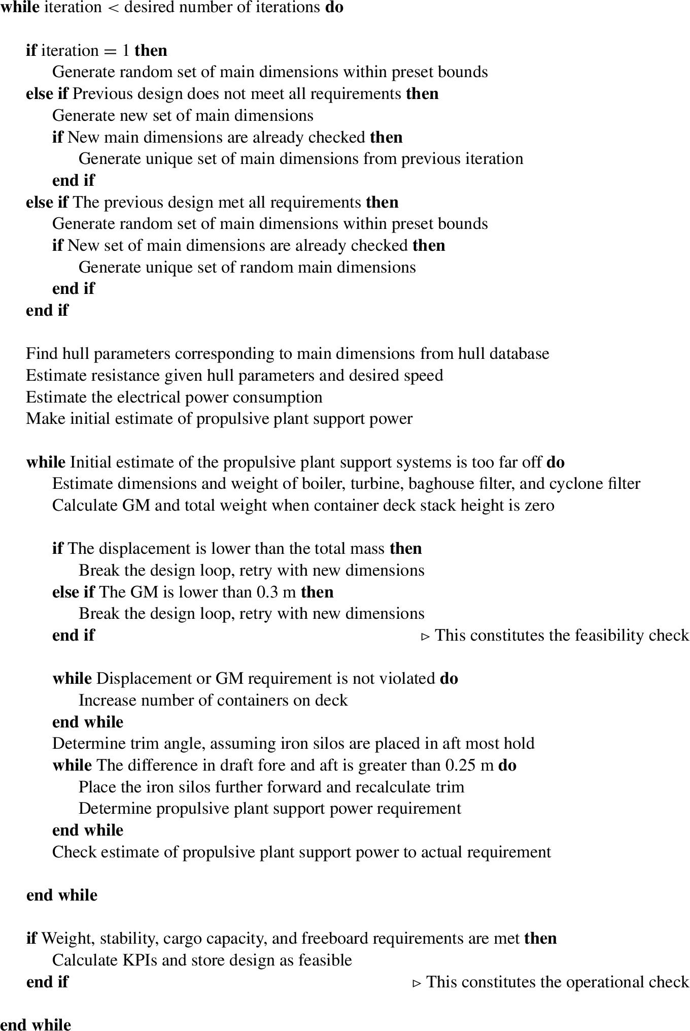
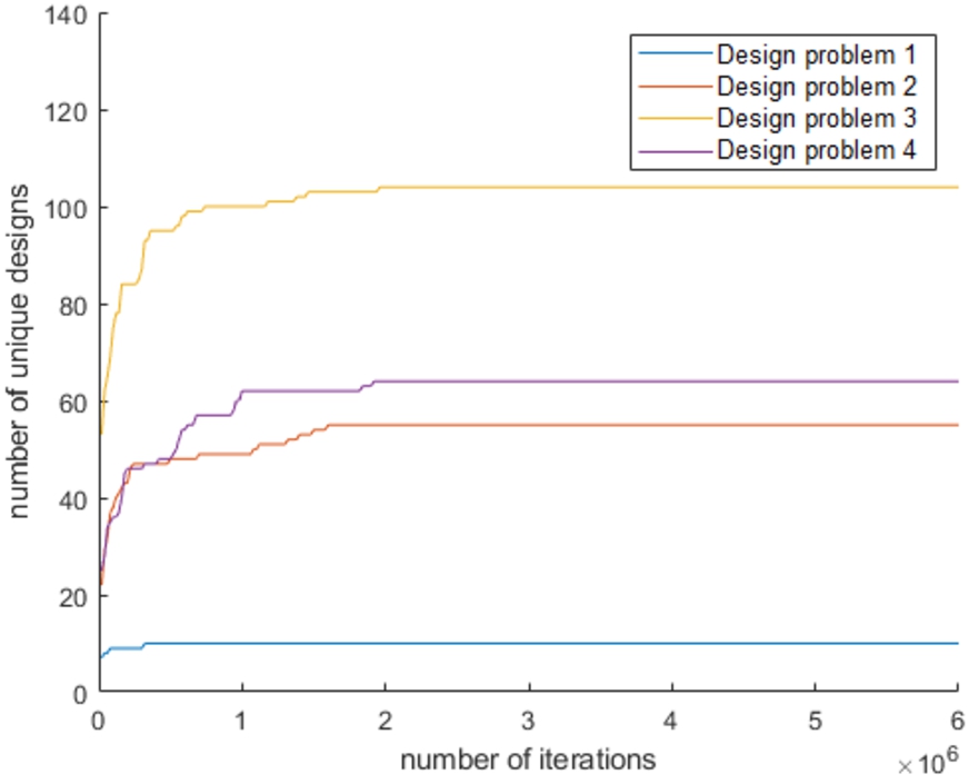
The model explores the design space by performing a design loop for a predefined number of times (Algorithm 1) to solve the four design problems described in Section 3.1. This pre-set number of iterations was found by performing a convergence study. As illustrated in Fig. 3, after approximately 2 million iterations, very few new, sufficiently unique designs were generated. Despite convergence after roughly 2 million cycles, this study completed 6 million cycles to increase confidence of convergence. Running the design loop sufficiently long for convergence takes approximately 2 hours on a personal laptop.
Fig. 3.
Number of new, sufficiently unique designs over design loop iterations.
The designs are considered unique if the length is at least 5 meters apart, the draft is 1 meter apart, the beam is at least 2.6 meters apart, or the depth is 2.45 meters apart. Once the design loop is completed, a proposed ship design consisting of a set of main dimensions is checked against a set of requirements. For feasible designs, the KPIs are determined and a new, randomly chosen set of main dimensions is generated to find another design. If the design does not meet the requirements, the main dimensions are changed according to the shortcoming of the design, and the process is repeated.
2.2.Modeling assumptions of the iron fuelled propulsive plant
In order to develop the parametric design model for iron fuelled ships, assumptions were necessary related to the propulsive plant. In a previous feasibility study on iron fuel for shipping, it was found that a heat engine on a Rankine cycle is the most suitable, readily available heat engine for iron fuelled ships [17]. The research in this paper assumed that iron fuelled ships run on a reheated, superheated Rankine cycle, modelled after the Ultra Steam Turbine (UST) plant developed by Mitsubishi industries [15]. It was assumed that the electric consumer power and propulsive plant support power are extracted from the main driver with a Power-Take-Off – Shaft Generator, to prevent the necessity for polluting diesel-generators.
In addition, it was assumed that there is one single boiler that produces the required steam output. For this initial study, redundancy and optimisation of the power plant design itself were outside the scope. The heat exchangers in the boiler are tube and shell heat exchangers, since the working fluid is pressurised. The superheated steam is converted to mechanical power using a high pressure, intermediate pressure and a low pressure turbine. The oxide particles are filtered out of the exhaust stream with cyclone filters and a baghouse filter. The cyclone filters extract the majority of the particles from the exhaust stream. However, a very high filtering efficiency is required to comply with particulate matter regulations and to maintain the circularity of iron fuel [17]. An additional baghouse filter is required to filter out the remaining particles after the cyclone filters.
The iron powder is stored on board in vertical silos which are placed in one of the cargo holds. The silos are placed in one of the cargo holds so the silos with oxide powder can be lifted out of the holds as a whole, and replaced with silos which are filled with iron. This ensures quick loading and unloading of the different powders on board, as illustrated in Fig. 4.
Fig. 4.
Proposed iron silos location and bunkering procedure.
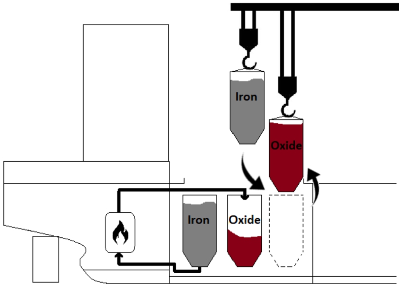
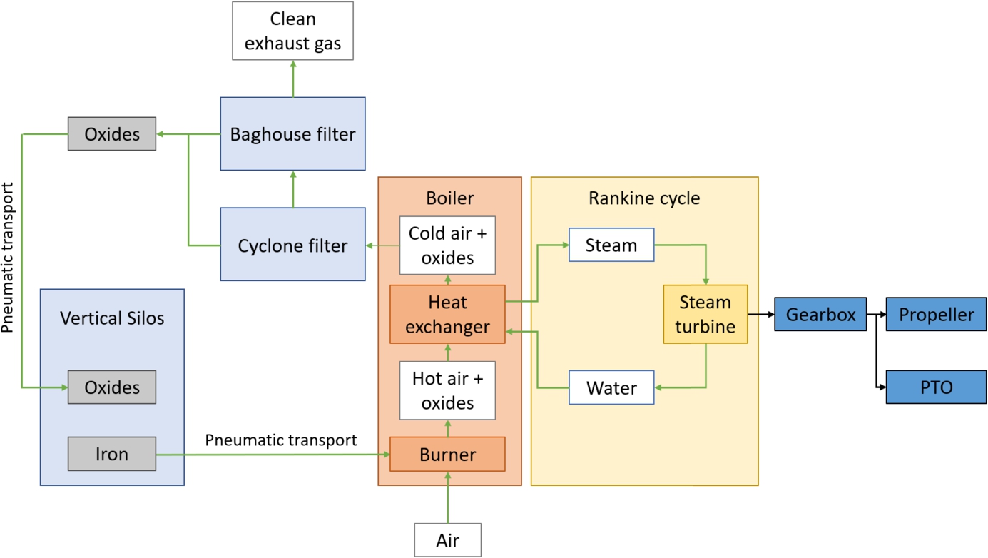
It is assumed that there is no need for separate silos for iron and oxide powder. Once an iron powder silo is emptied, it can be filled with oxide powder. The powders can be transported to and from the silos in several ways, though a two phase pneumatic transport seems most suitable [17]. Figure 5 provides a system diagram.
Fig. 5.
High level overview of the assumed iron fuelled propulsive plant. Powder handing systems are in light blue, iron combustion systems are in red, and energy conversion systems are in yellow. Fluid flows are denoted with green arrows and mechanical connections are denoted with black arrows.
2.3.Details of the parametric design model
In the first iteration, a random set of main dimensions is generated. These consist of the length, beam, depth, and draft. A parent hull shape is scaled to match with these main dimensions. The parent hull shape is modelled after the KCS hull shape, which is a standard benchmark design for container ship hull research [20], and is presented in Fig. 6. To simplify the model, the bulbous bow was removed from the parent hull shape. For the following iterations in the design loop geometric design properties of the hull shape are required. These geometric properties are the principal dimensions of the ship and the hull coefficients. These are interpolated from a database of geometric properties of approximately 17,000 hull shapes, which are all scaled versions of the parent hull shape according to the ratios presented in Table 1.
Fig. 6.
Parent hull shape without superstructures, with green indicating wetted surface area.
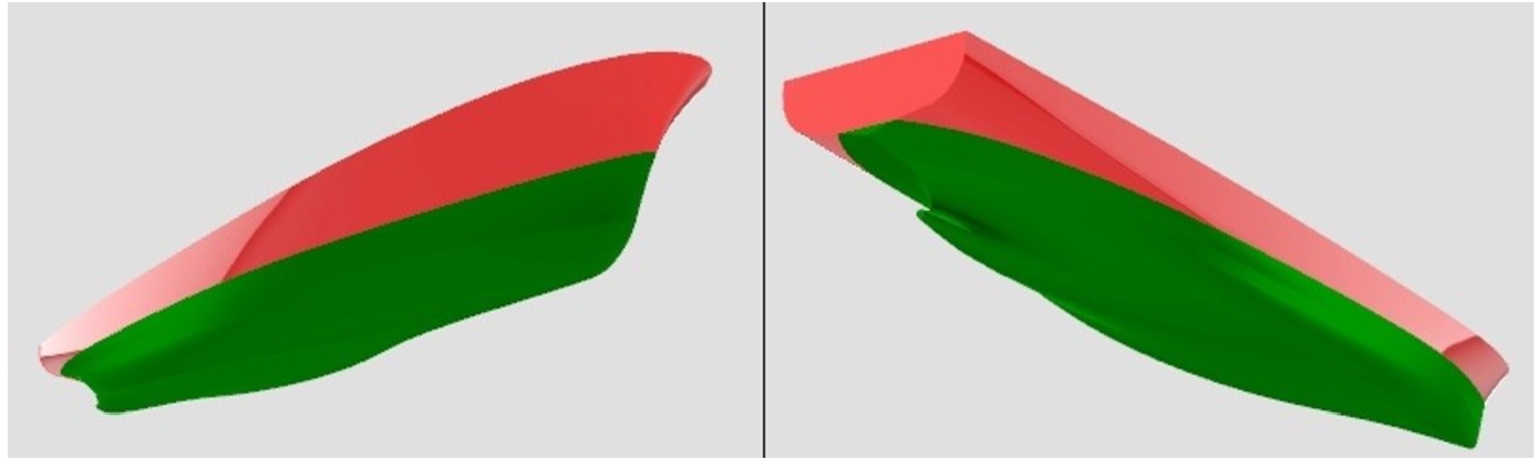
Table 1
Geometric parameters of the parent hull shape and the typical range for container ships
| Typical range | Parent hull shape | |
| 5.7–7.8 | 6.09 | |
| 9.9–13.5 | 11.4 | |
| 0.56–0.64 | 0.603 | |
| 0.57–0.65 | 0.633 | |
| 0.95–0.98 | 0.953 | |
| 0.78–0.83 | 0.780 | |
| 5.6–5.9 | 5.85 |
Once the geometric properties of the hull are obtained, the resistance and propulsive power,
The power consumption of the support systems is modelled as the sum of: the power consumed by blowing air through the burner, the heat exchanger and filtration systems, the power required to compress the working fluid, and the power required to transport the powder on board using pneumatic transport (Equation (5)). A finalised design is necessary to make a more detailed estimation. Later, when the design is finalised, the propulsive plant support power is determined in more detail and the design is corrected if the initial estimate of
The efficiency of iron fuelled ships is quite low, due to the assumed steam cycle, which has a cycle efficiency of only 0.32. The boiler efficiency, turbine efficiency, compressor efficiency and the power plant support power reduce the overall efficiency further.
2.4.Modelling the power plant
Using the main dimensions and required shaft power, the main components of the iron fuelled propulsive plant are designed. The weight and volume of the turbine is estimated by designing the rotor in such a way that the turbine operates at peak efficiency at full power. The boiler dimensions are estimated by using an empirical method to estimate the heat transfer coefficients for the shell and tube heat exchangers [9]. The baghouse filter dimensions are estimated using a method for preliminary design proposed in [6]. The cyclone filters are dimensioned such that they fit on the aft end of the vessel, where it is assumed that the boiler and baghouse filter are placed. For all components, a reasonable match is found compared to existing product estimates for weight, dimensions, and volume.
Since no iron fuelled boilers exist yet, the weight and dimensions of the boiler was compared to oil fuelled boilers. The size and weight of the iron fuelled boiler are in the same order of magnitude as the weight and dimensions of the oil fuelled boilers [11]. The working pressure is 24 bar for the industry examples, where it is 100 bar for the modelled boilers. For the iron fuelled ships, high pressure steam is assumed, as that increases the cycle efficiency. The weight of the industry examples have been scaled by a factor of 3 to account for the difference in pressure. This scaling factor is based on the increase in required wall thickness of the pipes in the boiler due to this pressure difference. The model has a good match with the industry examples. The comparison between the designed boiler and the industry examples is provided in Fig. 7.
Fig. 7.
The predicted boiler volume and weight as a function of steam production, with industry examples from [11]. Boiler weight of industry examples has been scaled by a factor of 3.
![The predicted boiler volume and weight as a function of steam production, with industry examples from [11]. Boiler weight of industry examples has been scaled by a factor of 3.](https://content.iospress.com:443/media/isp/2023/70-1/isp-70-1-isp220012/isp-70-isp220012-g008.jpg)
2.5.Modelling vessel stability and layout
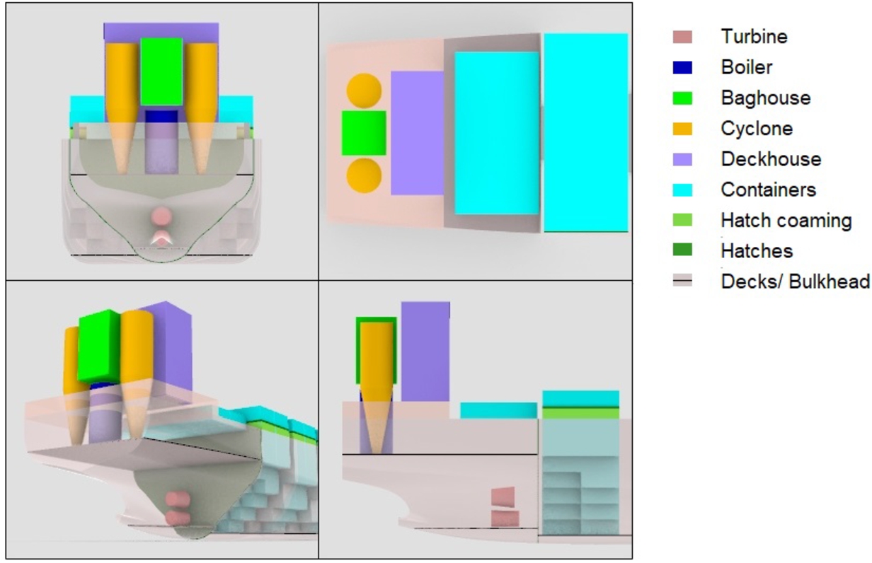
Once the dimensions of the components are determined, they are fitted in the hull as simple geometric shapes. All the designs have the same general layout. This layout is chosen to maximise the available cargo space. The boiler and filtration systems are quite large, and placed in the aft of the vessel near or in the machine room with the turbine and the baghouse (see Fig. 8). In the chosen layout, the boiler, cyclone and baghouse cannot be stored in the machine room and will likely protrude through the main deck. An additional superstructure is required to accommodate these components. Initially, the powder silos are placed in the aft most cargo hold. It is assumed that the cargo holds are filled with containers, each weighing 14 ton. The weight and centre of mass of the machinery, structural steel of the ship and superstructure, outfitting weight and deadweight components is estimated and a center of gravity can be found. The model then checks if the ship meets the following basic design requirements without any containers on deck:
Fig. 8.
Different views of the machine room layout. The boiler, baghouse filter and cyclone filters are assumed to be accommodated in an additional superstructure.
The displacement is larger than the total ship weight
The GM is higher than 0.3 m, ensuring lateral stability
If the feasibility check is passed, the container stack height is incrementally increased until one of the above requirements is violated or if the container stack height becomes too high to comply with line of sight requirements. Once the maximum number of containers has been found, the iron and oxide silos are incrementally placed forward until the trim is within acceptable bounds. Once a design has been completed, the operational check is performed, according to the following four design requirements:
The number of containers the ship can carry must be within a 0.95–1.2 interval of the desired cargo carrying capacity
The GM must be between 0.3 and 2 meter to maintain stability and reduce roll accelerations.
The displacement is within 1% of the total weight of the vessel
The freeboard cannot be too low and its minimum value is calculated according to [21].
If any of these conditions are not met, the main dimensions are varied according to the requirement that is violated. The design loop is repeated for these new main dimensions and this process is repeated until a design is found which complies with all requirements. Once the model has found a design which meets all the design criteria, the design is stored and the model repeats the design loop with a new randomly generated set of main dimensions. This process is repeated until the designated number of design loops have been completed. To prevent the model from finding the same design multiple times, only unique designs are stored.
2.6.Key performance indicators
Once a feasible design is found, the following KPIs are determined and used to rank the different designs:
Net Present Value (NPV) is used to measure the overall economic viability of operating the ship. It is assumed that the interest rate is 2%, and that the lifetime of the ship is 25 years.
The Minimum freight rate is defined as the minimum rate per container to break even for all costs considered in the model and determined as the minimum rate the shipowner must charge to compensate for the operational and voyage related costs.
Required capital investment is estimated using the empirical equations from [21] which base capital investment as a function of main dimensions, weight of the structural steel, block coefficient, and total required shaft power. The specific details of how this was implemented in this model can be found in Appendix A of [7].
Specific energy consumption (SEC) expresses the energy consumption that is required per container per transported mile in a voyage.
The NPV is used to determine the economic viability of operating the iron fuelled ship at the given operational profile. The ratio between the minimum freight rate and contemporary freight rates is used to give insight when an operational profile is unlikely to be viable. The required capital investment cost is included in this analysis because all the investment costs are considered. The SEC is used to estimate the impact operating the ship has on land-based infrastructure. For ships with a high SEC, more renewably produced hydrogen is required to reform the oxide back to iron, so a low SEC is desired. It is assumed that iron combusts without the need for any fossil pilot fuel, so ecological KPIs such as the EEDI index cannot be applied here.
The model is used to find designs with the highest NPV, representing the economical viability of the ship, and the lowest SEC, representing the amount of renewably produced energy the ship consumes. The model estimates the required investment from empirical formulas for the cost of: steel [21], labour [16], engineering working hours [5] and machinery and outfitting [18,25]. The annual operational costs consist of the crew cost, supplies and lubrication cost, maintenance, insurance, docking and administration cost and is computed using the estimation methods proposed in [18,25]. The annual voyage costs are estimated from the calculated number of annual voyages using the empirical formulas in [17,24]. It is assumed that the ship operates in short sea shipping and thus no canal fees apply. The cargo handling fees, port fees [24], and cost of reforming the oxide back to iron are incorporated in the cost per voyage. The cargo handling fees and port fees are estimated by assuming that they are equal to the rates of the port of Rotterdam, as data were available for this port on [24]. The price of iron was assumed to be € 860 per ton compared to an HFO price of € 600 per ton, while the cost of iron reforming was assumed to be € 115 per ton of oxide powder, as reported in [17]. This price is based on the assumption that renewably produced hydrogen costs € 1 per kilo in a future, clean energy economy. The revenue per container per mile is estimated using data from contemporary freight rates.
As no full scale ships exist that runs on iron fuel, the designs that the model predicts cannot be compared or validated directly against existing ships. Instead, the parametric model was validated by means of the method proposed in [22] for validating design methods. The details of this validation study can be found in [7].
3.Results
The parametric design model is used to explore the design space of iron fuelled ships. First, high level design implications of iron fuelled ships are identified (Section 3.1), followed by various design problems covering differing operational profiles on the design are evaluated (Section 3.2), after which the economic viability (Section 3.3) for iron fueled ships is explored. Finally, the most viable operational profile is then compared to the predicted performance of a similar ship fuelled with other alternative fuels (Section 3.4).
3.1.Design implications of iron fuelled ships
To determine the design trends within the design space of iron fuelled ships, the parametric model is used to generate designs for the four design problems given in Table 2. These are chosen such that the power requirement, cargo capacity and energy storage capacity increases for each design problem. The difference between relatively small and large iron fuelled ships can then be evaluated.
Table 2
Design problems (dp)
| Problem id | TEU [-] | Speed [kn] | Range [nm] |
| 1 | 500 | 12 | 1,000 |
| 2 | 1,500 | 16 | 1,750 |
| 3 | 2,500 | 20 | 2,250 |
| 4 | 4,000 | 22.5 | 3,000 |
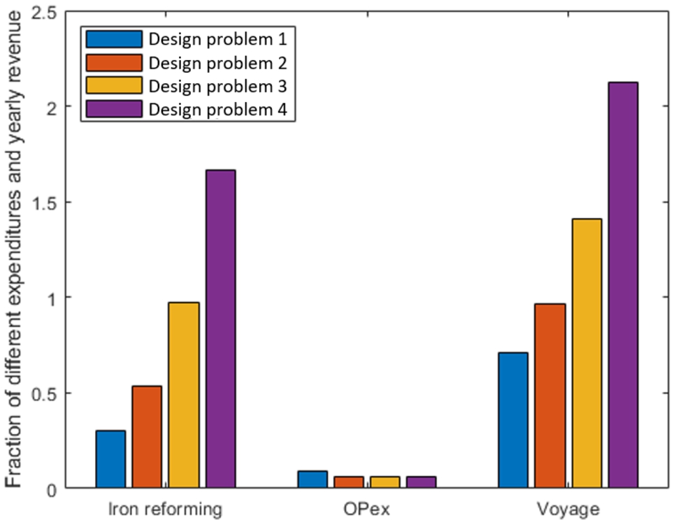
Figure 9 shows the results of the required capital expense versus the NPV, where the blue and orange symbols relate to the relationship of NPV and capital investment to the specific energy consumption (SEC), respectively. Here, each of the design problems are represented by a cloud of points, where each point is a unique design. From this figure it can be seen that the relationship between the specific energy consumption and the NPV tends to be negatively linearly correlated, with a minimum SEC leading to the maximum NPV and the maximum SEC to minimum NPV. This is caused by the cost of reforming the oxide powder back to iron. As the energy consumption per container per mile increases, so do the annual costs of operating the vessel. Thus higher energy consumption leads to lower NPV. As shown in Fig. 10, this relation is relatively linear, since the variation in cost per design is dominated by the difference in fuel cost. Therefore, the annual operating costs are dominated by the energy efficiency. Since the annual revenue scales with the cargo carrying capacity, which does not change significantly for designs within a design problem, the NPV scales linearly with the energy efficiency of the ship. The ship corresponding to the highest NPV therefore also corresponds to the most energy efficient design.
Fig. 9.
NPV and capital investment of the designs for each of the design problems. ‘dp’ denotes design problem, blue relates to the NPV, and orange relates to capital investment.
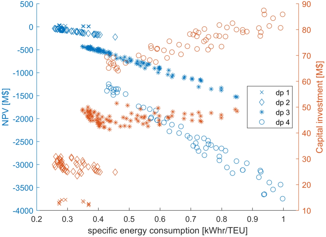
Fig. 10.
Fraction of different yearly expenses for ships with the lowest minimum freight rate.
From Fig. 9, it can also be seen that this ship also corresponds to a design with a low required capital investment, which inherently includes the initial cost of purchasing the iron. More energy efficient ships do not require as much iron, so the required capital investment for the iron is smaller for more energy efficient ships. Especially for design problem four, where a large energy carrying capacity is required, the most energy efficient ships have a lower required capital investment, further adding to the effect that energy efficient ships have a higher NPV. This effect is only significant when a large energy carrying capacity is required.
Since the design with the highest NPV corresponds to the most energy efficient ship, there is a single design which performs best economically and requires the least renewably reformed iron, thus minimising the required land-based infrastructure for reforming. Thus, there is a single design that is considered to be optimal per design problem, as further discussed in the paragraphs below and presented in Table 3.
Table 3
Properties of the designs with the lowest and highest specific energy consumption
| Design problem 1 | Design problem 2 | Design problem 3 | Design problem 4 | |||||
| Best | Worst | Best | Worst | Best | Worst | Best | Worst | |
| TEU capacity [-] | 549 | 497 | 1,645 | 1,477 | 2,724 | 2,610 | 4,175 | 3,834 |
| Efficiency [-] | 0.266 | 0.269 | 0.269 | 0.270 | 0.270 | 0.271 | 0.270 | 0.270 |
| Shaft power [kw] | 1,691 | 2,076 | 6,633 | 10,541 | 18,756 | 43,884 | 37,045 | 93,058 |
| Length [m] | 136.8 | 126.5 | 192.8 | 150.1 | 263.5 | 187.5 | 265.5 | 224.7 |
| Beam [m] | 20 | 22.9 | 31.4 | 31.4 | 34.3 | 34.3 | 40 | 42.9 |
| Depth [m] | 12.0 | 9.4 | 19.6 | 14.7 | 22.2 | 19.7 | 27.3 | 25.0 |
| Draught [m] | 6.6 | 7.2 | 10.0 | 10.95 | 12.6 | 16.3 | 15.7 | 21.0 |
For the considered design problems and assumed weight per container, it was determined that iron fuelled container ships are deadweight limited, despite the voluminous cargo they carry. The well performing designs that the model generates have volumetric space available to carry more containers, but the container carrying capacity is restricted by the available deadweight. Based on the underlying data from the parametric model, the well performing designs of design problems three and four, the weight of the iron and oxide powder is significant, covering between 25 and 30% of the displacement of the ship respectively. For design problem one, the weight of the oxide powder is only 6%.
Design trends can be identified by comparing the highest NPV design with the lowest NPV design. The difference in required shaft power between the best and worst performing designs is significant. This is mainly caused by the difference in resistance. The efficiency in this table is defined as the ratio of propulsive and electric consumer power and the energy content of iron consumed in the boiler.
According to [21], the cargo carrying capacity of ships can be increased with the lowest resistance penalty by increasing the depth and favouring long ships over ships with a large draught. This is also seen in the results of the model: the best performing ships have a large L/B ratio, whereas the worst performing have a low L/B. Additionally, the depth of the best performing ships is high and the draught is low. The design driver of the main dimension of iron fuelled ships is to provide enough displacement while minimising resistance.
Fig. 11.
Longitudinal view of the vessel, showing the silos arrangement.
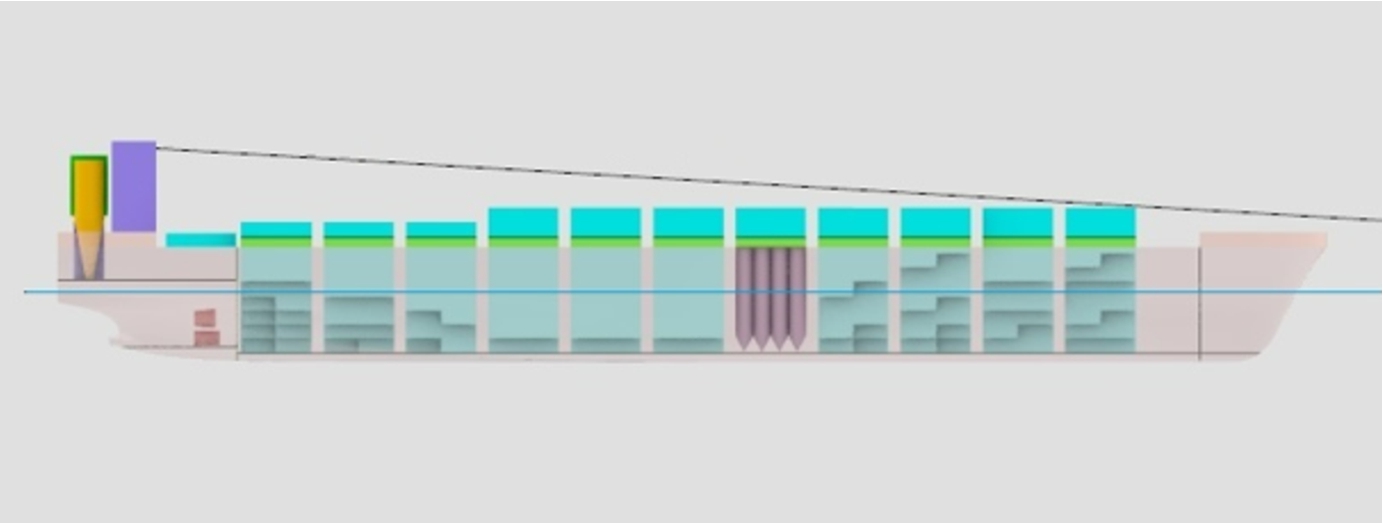
Using the results of the design problems, it was also found that iron fuelled ships with the chosen general arrangement and hull shape have a tendency to trim by stern. To compensate for this trim, the iron silos have to be placed relatively far forward in the hull (see Fig. 11). This increases the transport distance and power required to transport the iron and oxide powder to and from the machine room. For ships with a low required energy storage capacity, the weight of the iron and oxide may not be sufficient, and containers must be moved forward or ballast tanks added. It is likely that a hull shape with its center of buoyancy further aft is preferred for iron fuelled ships with this chosen general arrangement.
Fig. 12.
Variation of main dimensions as a function of desired speed.
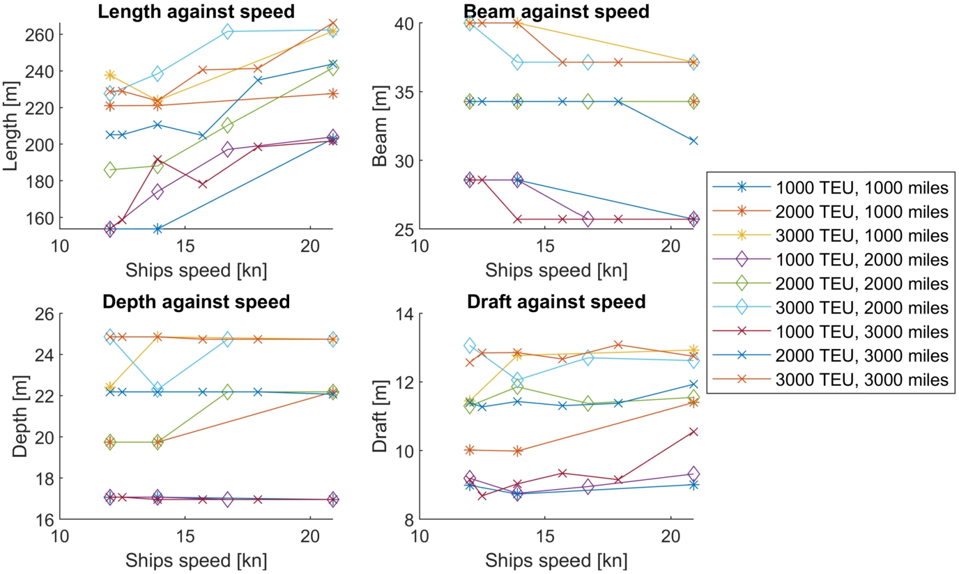
Fig. 13.
Variation of main dimensions as a function of range.
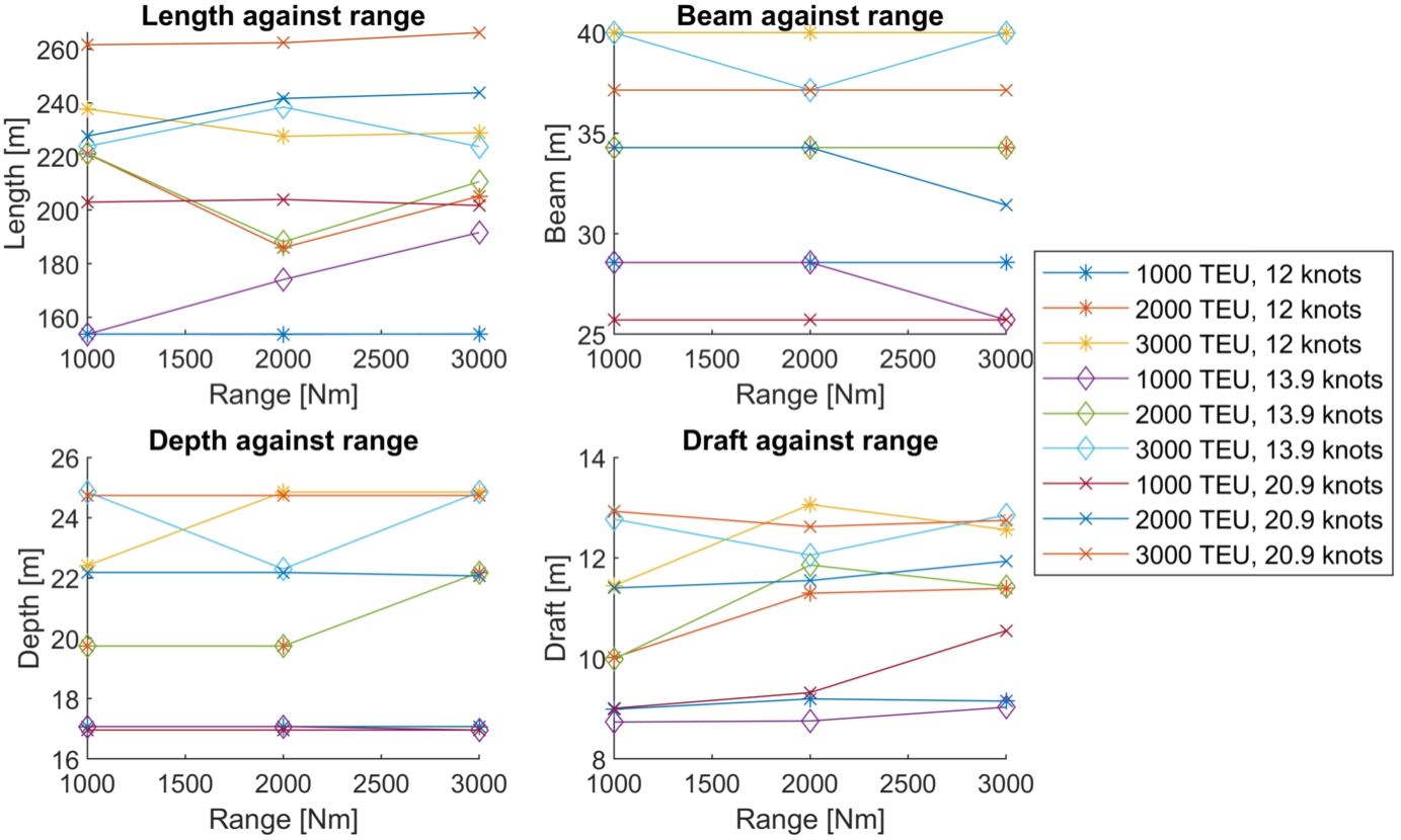
Fig. 14.
Variation of main dimensions as a function of cargo capacity.
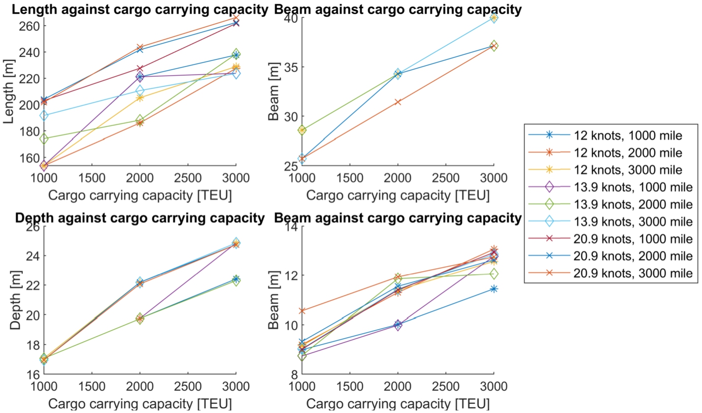
3.2.Influence of operational profile on design of iron fuelled ships
The influence of the required energy storage capacity of iron fuelled ships can be seen in the main dimensions of the designs, as depicted in Figs 12, 13 and 14. Increasing the speed increases the required energy capacity of the ship significantly and the main dimensions must be increased to accommodate this weight (Fig. 12). Interestingly, at high speeds, the beam is reduced compared to ships with a low speed, even though much more displacement is required for high speed as demonstrated in the upper right plot in Fig. 12. The length, depth and draught are increased to compensate for the displacement requirement and reduced beam. When all iron is combusted, the weight of the iron is approximately 2,100 ton for the ship carrying 2,000 containers for 2,000 miles at 12 knots, whereas the oxide weighs almost 8,000 ton for the ship with the same cargo capacity and range, but at 20.9 knots.
Similar, yet less drastic compared to Fig. 12, behaviour is shown as a function of range (Fig. 13). A ship sailing at 13.9 knots, carrying 2000 containers and sailing 1,000 miles carries 1,400 tons of oxide powder, while a ship with the same speed and cargo, but with a range of 3,000 miles carries 4,200 tons of oxide powder. Though the displacement needs to be significantly larger for ships with a higher range, the speed has a greater effect on the main dimensions. The cargo carrying capacity has the most obvious effect on the main dimensions (Fig. 14) compared to range and speed.
3.3.Influence of operational profile on the economic viability of iron fuelled ships
The results of the parametric design model are used to give insight in the viability of different operational profiles of iron fuelled ships. Figure 9 showed that the NPV for all designs of design problems two, three, and four are negative, indicating that these profiles are not viable. However, the NPV is estimated using a freight rate per container per mile transported that is based on contemporary freight rates. It is expected that freight rates will increase if the shipping industry switches to alternative fuels, because these fuels are generally more expensive and require specialised equipment. Because it is difficult to predict how freight rates will change in an alternatively fuelled shipping industry, the NPV may not be suitable to identify viable operations for iron fuelled ships. Instead, the minimum freight rate has been selected as the economic indicator for the performance of the vessels because it determines the minimum rate the ship owner must charge to compensate for the operational and voyage related costs.
Figures 15, 16 and 17 show the ratio between the minimum freight rate and the estimated freight rate based on contemporary rates for different cruising speed, range, and cargo carrying capacity. Here is can be seen that the trends follow a logical pattern that an increase of speed and range leads to increased freight rates and that an increase in cargo carrying capacity leads to reduced freight rate fractions. According to this model, the freight rate needs to be almost four times higher than contemporary rates to break even for fast ships with a low cargo capacity and high range.
Fig. 15.
Ratio of minimum freight rate to actual freight rate as a function of speed.
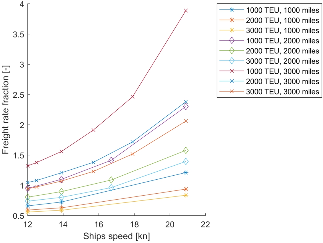
Fig. 16.
Ratio of minimum freight rate to actual freight rate as a function of range.
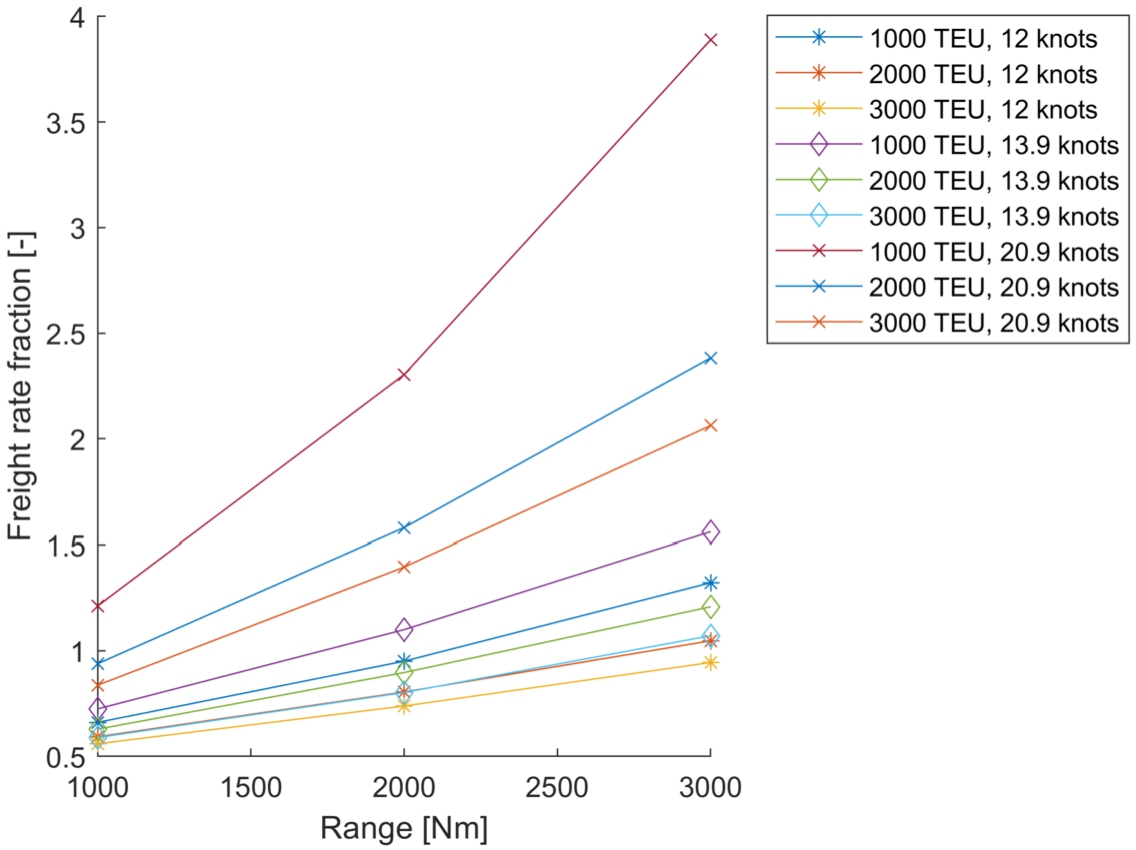
Fig. 17.
Ratio of minimum freight rate to actual freight rate as a function of cargo capacity.
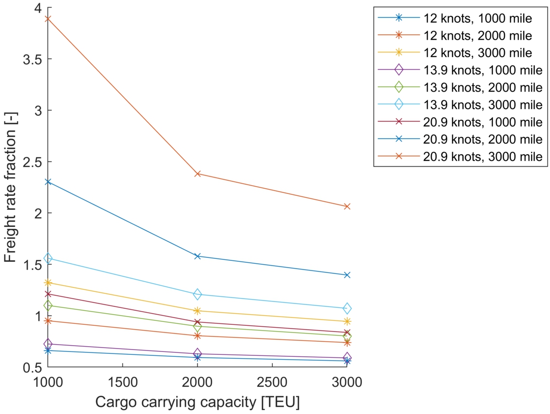
These results provide only a initial quantitative assessment of the viability of iron fuelled ships, due to the uncertainty regarding the freight rate when alternative fuels are more widely used in the shipping industry. Despite that, the general trend in these figures show that iron fuelled ships are more profitable for short voyages, large cargo carrying capacity and low speeds. For these voyages, the annual costs are dominated by the operational costs, port costs, and cargo related costs [17,24]. Since the ship spends a larger fraction of time in port for short voyages, the energy consumption is lower and so are the corresponding costs to reform oxide back to iron. The cost per unit energy is quite high for iron, and the overall efficiency of iron fuelled ships is quite low, as can be seen in Table 3. For longer voyages, the ship is under transit for a larger portion of time, and thus, the cost of reforming dominate the other expenses and the ship is less likely to be viable (see Fig. 10).
3.4.Comparison of iron fuelled ships and other alternative fuels
Section 3.3 identified that iron fuelled ships are economically viable for short voyages, slow sailing speeds, and large cargo carrying capacity. The most profitable operational profile for iron fuelled ships that has been identified is:
Cruising speed is 13.9 knots
Ship range is 1000 nautical miles
Cargo carrying capacity is 3000 TEU
The iron fuelled ship design that corresponds to this operational profile is used as a benchmark to compare the potential performance of the ship if it were powered with other alternative marine fuels. The following propulsive plants are used to compare with the iron fuelled propulsive plant:
Methanol with Internal Combustion Engine (ICE)
Methanol with Low Temperature Proton Exchange Membrane Fuel Cell (LT-PEMFC)
Ammonia in Solid Oxide Fuel Cell (SOFC)
Compressed hydrogen (700 bar) in LT-PEMFC
Liquefied hydrogen in LT-PEMFC
The weight and volume of the machinery and fuel with storage equipment is estimated based on scaling values from an online database published by MARIN [19]. It is assumed that the total displacement of the vessel is the same compared to the iron fuelled ship. The difference in weight between the iron fuelled propulsive plant and the propulsive plant under consideration is compensated with extra containers, if there is sufficient cargo space for more containers.
The machinery and energy storage equipment is fitted in the original design of the iron fuelled ship to estimate how much cargo space is available if the ship were equipped with a different propulsive plant. For instance, the required tanks for compressed hydrogen are quite large and thus at least one entire container hold is reserved for the tanks. Methanol is liquid under atmospheric conditions, and can be stored in the wing tanks. It is assumed there is no reduction in available cargo space due to the methanol tanks.
The operating cost and required capital investment for the propulsive plant is estimated using the database by MARIN [19]. The NPV of ships with a different propulsive plant can be estimated based on the input from this database. The results are presented in Fig. 18 and in Table 4. Table 4 shows that the NPV is quite low for the iron fuelled ship compared to the other fuels considered. This can be explained by two phenomena: first, the high cost and consumption rate of iron powder, and second, the high mass of iron. First of all, the total efficiency of iron fuelled ships is relatively low due to the low cycle efficiency of a Rankine cycle. In combination with the high cost of oxide reforming per unit energy, this results in relatively high annual bunkering cost.
Fig. 18.
Expenses and revenue for ships with different propulsive plant.
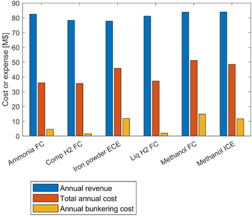
Table 4
Comparison of iron fuelled ship and other fuel types
| TEU [-] | CAPEX [M$] | NPV [M$] | |
| Methanol ICE | 3526 | 36.77 | 658 |
| Methanol FC | 3523 | 56.26 | 586 |
| Ammonia FC | 3466 | 40.85 | 785 |
| Compressed hydrogen FC | 3291 | 47.83 | 790 |
| Liquefied hydrogen FC | 3410 | 59.16 | 785 |
| Iron powder ECE | 3271 | 36.96 | 592 |
The cargo carrying capacity of the iron fuelled ship is limited by the displacement due to the high mass of iron and oxide powder. Since the total mass of the other propulsive plants is lighter than the iron fuelled propulsive plant, the cargo carrying capacity of these ships is higher, resulting in a higher annual revenue.
The results from this model are based on estimated scaling values for cost, volume, and weight of propulsive plants, and thus the uncertainty in these scaling values is large. However, since very little full scale examples in marine applications exist for these propulsive plants, it is not possible to place an exact value on this uncertainty. Therefore, the uncertainty in the final results is also very large. This analysis is included to illustrate the limiting factors of iron fuelled ships; namely, the low efficiency, high cost, and high mass of iron may make the fuel potentially less attractive compared to other fuels.
4.Conclusion
In this research, a parametric design model was developed for iron fuelled ships to help identify design trends and understand initial viability of iron powder as fuel. The parametric design model varies the main dimensions of a standardised container ship hull shape. In this model, a single parent hull shape was used to describe the hull and was based on the contemporary design of container ships, which is designed for high speeds and a large volume cargo.
One of the main conclusions was that iron fuelled container ships are displacement limited, instead of volume limited like conventionally fuelled container ships. This is mainly caused by the mass of the iron and oxide powder. Due to the low efficiency of the steam cycle upon which iron fuelled ships are assumed to run, a high mass of iron powder needs to be stored on board. The main dimensions of the designs in this research are thus mainly driven to provide sufficient displacement for the least resistance.
It is found that the filtering equipment required to filter out the oxide particles from the exhaust stream is quite large. The baghouse filter and cyclone filter are assumed to be placed above the machine room, where the boiler is also located. These large systems require an additional superstructure on the aft end of the vessel. Given the parent hull shape that is used in this analysis, the designs have a tendency to trim stern down because most systems are placed on the aft end of the vessel. In the designs generated by the model, the iron silos need to be placed relatively far forward to compensate this trim.
Due to the high costs of reforming iron oxide powder back to iron powder, and the low efficiency of iron fuelled propulsive plants, iron is a relatively expensive fuel. Iron fuelled ships are therefore more suitable for ships that have a low annual energy consumption, such as slow sailing ships that operate on short voyages. For shorter voyages, the ship spends a larger fraction of the operational time in port, where the power requirement is lower. Given a freight rate that is based on contemporary container freight rates, it was found that iron fuelled ships are viable for relatively low speeds, relatively large cargo carrying capacity, and operating on short voyages.
The performance of an iron fuelled ship with this operational profile was compared to the performance of the ship if it were powered by a different propulsive plant. It was found that the costs of operating the ship are relatively high compared to other fuels. Additionally, the weight of the iron and oxide reduces the cargo carrying capacity of the vessel, so the annual revenue of iron fuelled vessels is lower. Because of these two effects, the estimated NPV of iron fuelled ships is lower than that of most other alternative fuels.
5.Future work
Given the fact that iron powder boilers are still in development, the results of this study cannot yet be validated using full scale examples. As research and technology progresses in both iron combustion and the associated boilers, it is suggested to revise the models provided here to get a more accurate assessment of the potential and feasibility. This area of future work also applies to the economic analysis comparing iron powder to other alternative fuels. Improved estimations in these areas will help add credibility to the conclusions made in this study.
Based on the conclusion that iron fuelled ships are deadweight limited, it seems that a conventional container ship hull does not suit iron fuelled ships. In future work, the parametric design model should be expanded to have the hull shape variable as well. For instance, the block coefficient may be a better way to increase the displacement of a deadweight limited vessel than a change in the main dimensions. Additionally, the tendency to trim may be better solved by changing the hull shape so that the longitudinal centre of buoyancy moves further aft. By having more geometric parameters of the hull shape variable in the model, more representative results may be obtained.
While iron powder did not appear economically optimal compared to other alternative fuels according to this initial analysis on NPV, this is not reason alone to abandon the potential use of iron powder as a marine fuel. The cost, volume and weight of the components in the propulsive plants were estimated using characteristic scaling values. The uncertainty of these scaling values is large, which reduces the validity of this comparison. Additionally, the choice for a suitable alternative fuel is not solely based on the economic performance of a fuel. For instance, ease of storage and transportation, available land-based infrastructure or safety considerations greatly impact the choice for an alternative fuel. Iron may be easier to handle and may not require additional safety measures or inspections in comparison to other alternative fuels [17]. The potential cost implications related to ease of use, safety, and maintenance procedures have not been included in this analysis, but are a clear area of future study. Finally, it is uncertain whether the modelled systems are actually technically practical and feasible, both for an iron fuelled propulsive plant as well as the other alternative fuels. For most of the considered propulsive plants, there exist no full scale application that proves the feasibility of the system. Considerations such as ease of maintenance or the lifetime of components are not taken into consideration in this research. Further research is required to identify how attractive iron powder as a marine fuel is, based on a more thorough set of properties than the NPV of the ship alone.
6.Funding
The authors report no funding.
7.Conflict of interest
The authors have no conflict of interest to report. Austin A. Kana is an Editorial Board Member of this journal, but was not involved in the peer-review process nor had access to any information regarding its peer-review.
8.CRediT authorship contribution statement
Jochem de Kwant Conceptualisation, Investigation, Methodology, Software, Writing – Original Draft, Writing – Review & Editing Robert Hekkenberg Conceptualisation, Supervision, Writing – Review & Editing Apostolos Souflis-Rigas Writing – Review & Editing Austin A. Kana Conceptualisation, Interpretation of data, Supervision, Writing – Review & Editing
Acknowledgements
This work was performed as part of the MSc thesis for the lead author, [7]. The thesis was performed in Marine Technology at Delft University of Technology and the authors would like to acknowledge Delft University of Technology for their support of this research.
References
[1] | P. Balcombe, J. Brierley, C. Lewis, L. Skatvedt, J. Speirs, A. Hawkes and I. Staffell, How to decarbonise international shipping: Options for fuels, technologies and policies, Energy Conversion and Management 182: ((2019) ), 72–88. doi:10.1016/j.enconman.2018.12.080. |
[2] | J.M. Bergthorson, Recyclable metal fuels for clean and compact zero-carbon power, Progress in Energy and Combustion Science 68: ((2018) ), 169–196. doi:10.1016/j.pecs.2018.05.001. |
[3] | J.M. Bergthorson, S. Goroshin, M.J. Soo, P. Julien, J. Palecka, D.L. Frost and D.J. Jarvis, Direct combustion of recyclable metal fuels for zero-carbon heat and power, Applied Energy 160: ((2015) ), 368–382. doi:10.1016/j.apenergy.2015.09.037. |
[4] | E.A. Bouman, E. Lindstad, A.I. Rialland and A.H. Strømman, State-of-the-art technologies, measures, and potential for reducing GHG emissions from shipping – a review, Transportation Research Part D: Transport and Environment 52: ((2017) ), 408–421. doi:10.1016/j.trd.2017.03.022. |
[5] | J.M.G. Coenen, Controlling engineering-to-order processes in shipbuilding, a model-based approach, PhD thesis, Technical University Delft, 2008. |
[6] | C.D. Cooper and F.C. Alley, Air Pollution Control: A Design Approach, Waveland Press, (2010) . |
[7] | J. de Kwant, Design implication and performance assessment of iron fuelled ships, MSc Thesis, Delft University of Technology, 2021, http://resolver.tudelft.nl/uuid:966ab159-1fae-463f-a53c-b7b2d42d369. |
[8] | C. Deniz and B. Zincir, Environmental and economical assessment of alternative marine fuels, Journal of Cleaner Production 113: ((2016) ), 438–449. doi:10.1016/j.jclepro.2015.11.089. |
[9] | D.A. Donohue, Heat transfer and pressure drop in heat exchangers, Industrial and Engineering Chemistry 41: (11) ((1949) ), 2499–2511. doi:10.1021/ie50479a030. |
[10] | J. Faber, S. Hanayama, S. Zhang, P. Pereda, B. Comer, E. Hauerhof, W.S. van der Loeff, T. Smith, Y. Zhang, H. Kosaka, M. Adachi, J.-M. Bonello, C. Galbraith, Z. Gong, K. Hirata, D. Hummels, A. Kleijn, D.S. Lee, Y. Liu, A. Lucchesi, X. Mao, E. Muraoka, L. Osipova, H. Qian, D. Rutherford, S.S. de la Fuente, H. Yuan, C.V. Perico, L. Wu, D. Sun, D.-H. Yoo and H. Xing, Fourth IMO GHG Study 2020, 1st edn, International Maritime Organisation, London, (2020) . |
[11] | K. group, Marine Steam Turbine, https://global.kawasaki.com/en/mobility/marine/machinery/steam_turbine.html, 2021, Accessed: 30-09-2021. |
[12] | J. Holtrop and G.G.J. Mennen, An approximate power prediction method, International Shipbuilding Progress 29: (335) ((1982) ), 166–170. doi:10.3233/ISP-1982-2933501. |
[13] | International Maritime Organisation, IMO working group agrees further measures to cut ship emissions. 23 October 2020 [Online]. Available from: https://www.imo.org/en/MediaCentre/PressBriefings/pages/36-ISWG-GHG-7.aspx [Accessed 1st November 2021]. |
[14] | International Maritime Organisation, Initial IMO GHG strategy [Online]. Available from: https://www.imo.org/en/MediaCentre/HotTopics/Pages/Reducing-greenhouse-gas-emissions-from-ships.aspx [Accessed 1st November 2021]. |
[15] | M. Ito, K. Hirakoa, S. Matsumoto and T. K., Development of high efficiency marine propulsion plant (ultra steam turbine), Mitsubishi Heavy Industries, Ltd Technical review 3: ((2007) ), 115251. |
[16] | H. Kerlen, Über den Einfluß der Völligkeit auf die Rumpfstahlkosten von Frachtschiffen, Technical Report, Technische Universität Hamburg, 1985. |
[17] | C. Kramers, N. van Rooij, T. Spee and V. Weijger, IJzer als brandstof voor schepen, Report, Maritiem Kennis Centrum, 2019. |
[18] | V. M., Cost estimate for ship desgin I, http://www.mar.ist.utl.pt/mventura/Projecto-Navios-I/EN/SD-1.3.2-Cost%20Estimate.pdf, 2021, Accessed: 11-10-2021. |
[19] | MARIN, Sustainable power, https://sustainablepower.application.marin.nl/, 2021, Accessed: 21-04-2021. |
[20] | Maritime and Ocean Engineering Research Institute (MOERI), KCS hull database: Benchmark container ship hull used in hydrodynamic research [Online]. Available from: http://www.simman2008.dk/KCS/kcs_geometry.htm [Accessed 1st November 2021]. |
[21] | A. Papanikolaou, Selection of main dimensions and calculation of basic ship design values, in: Ship Design: Methodologies of Preliminary Design, Springer Netherlands, Dordrecht, (2014) , pp. 69–292. ISBN 978-94-017-8751-2. doi:10.1007/978-94-017-8751-2_2. |
[22] | K. Pedersen, J. Emblemsvag, R. Bailey, J. Allen and F. Mistree, The ‘Validation square’ – validating design methods, in: ASME Design Theory and Methodology Conference, Citeseer, (2000) . |
[23] | J.A. Ryste, Assessment of selected alternative fuels and technologies, Report, DNV-GL, 2019. |
[24] | K. Terun, Assessing alternative fuel types for ULCVs in face of uncertainty, MSc Thesis, Delft University of Technology, 2020, http://resolver.tudelft.nl/uuid:84f29960-87fd-427b-bc9d-96b46f4bfe3c. |
[25] | D.G.M. Watson, Practical Ship Design, Vol. 1: , Elsevier, (2002) . |
[26] | H. Wiinikka, T. Vikström, J. Wennebro, P. Toth and A. Sepman, Pulverized sponge iron, a zero-carbon and clean substitute for fossil coal in energy applications, Energy & Fuels 32: (9) ((2018) ), 9982–9989. doi:10.1021/acs.energyfuels.8b02270. |
[27] | H.K. Woud and D. Stapersma, Design of propulsion and electric power generation systems, 2014, IMarEST. |


