
High energy density storage of gaseous marine fuels: An innovative concept and its application to a hydrogen powered ferry
Abstract
The upcoming stricter limitations on both pollutant and greenhouse gases emissions represent a challenge for the shipping sector. The entire ship design process requires an approach to innovation, with a particular focus on both the fuel choice and the power generation system. Among the possible alternatives, natural gas and hydrogen based propulsion systems seem to be promising in the medium and long term. Nonetheless, natural gas and hydrogen storage still represents a problem in terms of cargo volume reduction. This paper focuses on the storage issue, considering compressed gases, and presents an innovative solution, which has been developed in the European project GASVESSEL® that allows to store gaseous fuels with an energy density higher than conventional intermediate pressure containment systems. After a general overview of natural gas and hydrogen as fuels for shipping, a case study of a small Roll-on/Roll-off passenger ferry retrofit is proposed. The study analyses the technical feasibility of the installation of a hybrid power system with batteries and polymer electrolyte membrane fuel cells, fuelled by hydrogen. In particular, a process simulation model has been implemented to assess the quantity of hydrogen that can be stored on board, taking into account boundary conditions such as filling time, on shore storage capacity and cylinder wall temperature. The simulation results show that, if the fuel cells system is run continuously at steady state, to cover the energy need for one day of operation 140 kg of hydrogen are required. Using the innovative pressure cylinder at a storage pressure of 300 bar the volume required by the storage system, assessed on the basis of the containment system outer dimensions, is resulted to be 15.2 m3 with a weight of 2.5 ton. Even if the innovative type of pressure cylinder allows to reach an energy density higher than conventional intermediate pressure cylinders, the volume necessary to store a quantity of energy typical for the shipping sector is many times higher than that required by conventional fuels today used. The analysis points out, as expected, that the filling process is critical to maximize the stored hydrogen mass and that it is critical to measure the temperature of the cylinder walls in order not to exceed the material limits. Nevertheless, for specific application such as the one considered in the paper, the introduction of gaseous hydrogen as fuel, can be considered for implementing zero local emission propulsion system in the medium term.
1.Introduction
The shipping industry is now facing an important transformation phase in order to meet new regulations on pollutant emissions.
The upcoming stricter limitations on nitrogen oxides (NOx) and sulphur oxides (SOx) imposed by the International Maritime Organization (IMO) in MARPOL Annex VI, along with the introduction of energy efficiency indexes to assess the design and operation of ships [36,46], require an innovation of the entire process of ship design and, in particular, of the power generation systems on board.
As for the power plants, they are, to date, mostly based on Diesel engines fed by Heavy Fuel Oil (HFO) and Marine Diesel Oil (MDO). HFO and MDO based technologies are reliable and cost-effective, but their combustion processes produce significant amounts of NOx, SOx and, above all, CO2.
For this reason, in order to comply with the current and expected IMO requirements, it may be no longer sufficient the adoption of market ready solutions on board of the vessel, such as Selective Catalytic Reduction (SCR) and scrubbers. Therefore, recently, solutions based on innovative power plants and alternative fuels have been considered and start to be implemented [18,27,51,53].
As for alternative fuels, hydrogen (H2) is gaining ever more attention, particularly for feeding fuel cells (FC), as this solution allows for zero local emissions. In this context, several studies and projects [21,27,47] show that Polymer Electrolyte Membrane FC (PEMFC) fueled by H2 could be a viable solution on the medium-long term. H2 could also be used in Internal Combustion Engines (ICEs) with high efficiency, but in this case NOx would be produced and therefore zero local emissions cannot be achieved. There are, however, many factors that hamper a large scale diffusion of H2 as fuel for shipping, among these, the low energy volumetric density of H2 storage, the lack of a specific production and bunkering infrastructure and the lack of specific rules for safe handling on board [35].
Natural Gas (NG), on the contrary, has already been implemented on board. Indeed, ICEs fed by Liquefied Natural Gas (LNG) have the highest technology maturity among the possible solutions and represent, to date, a market ready alternative for ships that sail most of time in Emission Controlled Areas (ECAs) [18].
Studies and projects report that also Solide Oxide fuel cells (SOFC) fueled by NG could be a viable solution in the next future. Nevertheless, this fuel cells type has not reached today a level of technology maturity for the short term on board installation [15,27,29].
For both NG and H2 as marine fuels, storage still represents a problem in terms of costs and cargo volume reduction. The storage issue is particularly challenging if NG and H2 are stored in gaseous form [19].
The present study focuses on critical aspects of natural gas and hydrogen storage in terms of energy density and bunkering process and proposes a solution based on the GASVESSEL® project [31], where an innovative high energy density pressure vessel, currently designed to store NG, is going to be demonstrated.
In particular, the GASVESSEL® innovative containment system will be applied for the storage of H2 to feed PEMFCs. As previously mentioned, this solution allows for zero local emissions and is based on the only FC technology that has reached a technological maturity at least in sectors other than shipping [45]. In the paper, a case study where a Hybrid Power System (HPS) based on FCs and Lithium-ion (Li-ion) batteries is considered to power a small size ferry and a specific energy simulation model to assess the fuel consumption has been developed. Moreover, a process simulation model to analyze the pressure cylinder refilling process has been used.
2.Natural gas and hydrogen as fuels for ship propulsion
In this section, a perspective of using natural gas and hydrogen as fuels for ship propulsion is given. After presenting the main advantages and disadvantages of the two fuels, mainly in terms of environmental sustainability, an insight on the storage issue and the description of an innovative storage solution is proposed.
Though the discussion in the next paragraphs is focused on local emissions, when considering environmental sustainability of a fuel it is important to introduce a global approach. In fact, the reduction of local emissions would allow ships to sail in emission controlled areas, reducing environmental impact of pollutants in sensitive zones. However, in a global perspective, it should always be taken into consideration also the amount of greenhouse gases (GHG) emissions of the whole process, from fuel production to its utilization, the so-called Well to Propeller (WTP) emissions. From this standpoint, the recent DNV-GL report on the assessment of selected alternative fuels and technologies [26] points out that while hydrogen has zero Tank To Propeller (TTP) CO2 emissions, Well To Tank (WTT) CO2 emissions are comparable with WTP CO2 emissions of HFO and MDO if hydrogen is produced through methane reforming. As for natural gas, WTT emissions, including transport from extraction site to utilization site, are comparable with those of HFO and MDO, while TTP emissions can be cut up to 30% in comparison with the use of HFO/MDO [48].
2.1.Natural gas as a fuel for ship propulsion
As previously mentioned, TTP CO2 emissions of NG can be 30% lower with respect to the use of HFO/MDO [48]. However, this advantage can be greatly reduced by the methane slip, which occurs especially with dual fuel engines at low loads [37,52].
Nonetheless, the use of NG in ICEs allows an almost complete elimination of SOx and particulate matter emissions due to its chemical and combustion properties.
The NOx emissions can also be reduced by approximately 85%, thanks to the lean burn combustion process realized in spark ignited and dual fuel engines (gas Diesel engines, instead, require the adoption of SCR).
As a whole, this means that the expensive and bulky emission reduction systems that must be used when operating with oil fuels can be avoided. For these reasons, the use of NG is a way to bridge the gap between the use of current fossil liquid fuels and that of potentially sustainable and renewable ones such as H2.
NG can be stored in liquid state at atmospheric pressure at the temperature of −162°C in different types of normalized insulated tanks [35]. For ships, other than LNG carriers, that use LNG as fuel, the most used tank is indicated as type C, in single lobe or bi-lobe configurations. This is the only type of tank that allows, according to the standards, a limited accumulation of gas at a pressure of a few bars. This allows an easier management of the boil-off gas (BOG), which constitutes, in ships other than LNG carriers, only a fraction of the total gas flow required by the engines. When sailing, with an adequate thermal insulation of the tank, the BOG can be sufficient to keep the tank pressure constant in front of the decrease in the level of the liquid, due to engines fuel consumption. In conditions of mooring, with the propulsion engines switched off, the possibility of gas accumulation under pressure avoids the recourse to the Gas Combustion Unit (GCU). To handle BOG overproduction, another interesting option could be the use of FC systems, as they do not require a high feed pressure, are less sensitive to fuel composition variation and have higher efficiency than the internal combustion engines.
LNG as fuel is today used for different kind of vessels. As of March 2020, there are 178 LNG fuelled ships other than LNG carriers in operation worldwide, 207 confirmed orders and 123 vessels are ready for future LNG installations [25]. LNG fuel is mostly used by car/passenger ferry (44 operating vessels), but new orders focus on container ships (38 new orders), oil/chemical tanker (28 new orders) and other specialized kind of ships. Currently there is only one cruise ship in operation [6], but 33 are on order.
Another possibility to store natural gas is at high pressure and ambient temperature (CNG – Compressed Natural Gas). With this solution, the energy density is lower, but the complications connected to the installation and the operation of a cryogenic plant are avoided. This solution is not yet exploited, in ship propulsion, as the energy density of the fuel in terms of weight and volume is very low compared to LNG.
There are many studies that aim to increase the containment pressure and/or volume in order to improve the energy density of compressed gas [17,19]. One of these is the Compressed Natural Gas Transport System (GASVESSEL®) project, funded from EU under the H2020 program, which will be described in Paragraph 2.3.
2.2.Hydrogen as a fuel for ship propulsion
The main advantage of using hydrogen as fuel for shipping is to meet the requirements of zero TTP emissions.
One aspect that hampers the diffusion on a large scale of hydrogen as a marine fuel, as mentioned above, is the low volumetric energy density.
Hydrogen density in ambient conditions (1 bar and 25°C) is 0.081 kg/m3, more than four orders of magnitude lower than MDO density in the same conditions (about 840 kg/m3). Pure hydrogen reaches acceptable storage densities only at low temperature (liquefied hydrogen, LH2), high pressure (compressed hydrogen, CH2) or both high pressure and low temperature (cryo-compressed hydrogen, CCH2). Figure 1 reports pure hydrogen density as function of pressure and temperature. The numbered regions indicate typical storage conditions for LH2 (1), CH2 (2) and CCH2 (3).
![Hydrogen storage density under different pressure and temperature conditions [34].](https://content.iospress.com:443/media/isp/2020/67-1/isp-67-1-isp190274/isp-67-isp190274-g001.jpg)
An alternative to pure hydrogen for fuel storage on board could be hydrogen carriers, such as ammonia (NH3) and Liquid Organic Hydrogen Carriers (LOHC) [14,23,40], hydrogen from methane reforming, or the utilization of methanol in High Temperature PEM fuel cells [32].
This study focuses on storage solutions for CH2 because of their higher level of technology maturity, already achieved in automotive applications.
Table 1 shows the classification of cylinders for compressed gas storage. Cylinders of Type I have, to date, the largest market share. However, their high weight and low storage pressure (
Table 1
| Type I | Type II | Type III | Type IV | |
| Market share | 93% | 4% | ||
| Structure | All-metal cylinder; most commonly CrMo steel | Load-bearing metal liner hoop wrapped with resin-impregnated continuous filament; usually CrMo steel with glass fiber | Non-load-bearing metal liner axial and hoop wrapped with resin-impregnated continuous filament; usually aluminum with high performance glass and/or carbon | Non-load-bearing, non-metal liner axial and hoop wrapped with resin impregnated continuous filament; most commonly HDPE liner with carbon fiber |
| Pressure [bar] | up to 700 | up to 700 | up to 700 | |
| Indicative weight [kg/liter] | ||||
| Indicative cost [US$/liter] |
There are some issues to take into account for the choice of cylinder materials [28,39]:
cylinders of type I, II and III are subject to the hydrogen embrittlement of steel: this phenomenon can lead to early cracks and the consequent risk of cylinder explosion. The problem can be overcome by using aluminum alloys;
in Type IV cylinders there could be the phenomenon of permeation through polymeric lining, typical of all polymer in contact with gases.
2.2.1.Fuel cells
The most efficient and environmental friendly way to convert the chemical energy of H2 into electricity are FCs.
They are electrochemical devices that use hydrogen and oxygen to produce electricity, with only water and heat as by-products.
Table 2 reports a classification of fuel cells according to the most used electrolytes.
Table 2
| Fuel cell type | Relative cost | Sensitivity to fuel impurities | Operative temperature [°C] | Electrical efficiency (LHV based) [%] |
| AFC | Low | High | 80–100 | 50–60 |
| PAFC | Medium | Medium | 80–200 | 40* |
| MCFC | High | Low | 650–700 | 45–55* |
| SOFC | High | Low | 500–1000 | 50–60* |
| PEMFC | Low | High | 65–85 | 50–60 |
| HTPEMFC | Medium | Medium | 140–200 | 40–45 |
| DMFC | Medium | Medium | 50–120 | 20** |
* based on NG
** based on methanol
Electrolyte of Alkaline Fuel Cells (AFC) is made of potassium hydroxide and catalysts are usually nickel and silver. Phosphoric Acid Fuel Cells (PAFC) has the electrolyte layer formed by phosphoric acid spread over a porous substrate, which works as a support, and catalysts are usually formed by platinum or platinum alloys, dispersed on carbon. The Molten Carbonate Fuel Cells (MCFC) electrolyte is made of molten carbonate salt and a nickel catalyst. Solid Oxide Fuel Cells (SOFC) electrolyte is made of porous ceramic material (zirconia) and the catalysts are nickel, lanthanum, strontium and manganite. The Polymer Electrolyte Membrane Fuel Cells (PEMFC) electrolyte is made of polymer (often Nafion®) and the catalyst is platinum-based. In the case of High Temperature PEM Fuel Cell (HTPEMFC), the electrolyte can be phosphoric acid-doped polybenzimidazole (PBI-based) and the catalyst is platinum-based. The Direct Methanol Fuel Cell (DMFC) electrolyte is made of polymer and the catalyst is platinum ruthenium [27].
Fuel cells could be applied on board of vessels as Auxiliary Power Unit (APU) or as main power plant for propulsion system.
Another advantage of fuel cells, is the high efficiency even at partial load as presented in Figure 2, where the efficiency of different engines is shown as a function of the load.
Fig. 2.
Efficiency versus load of different power generation systems: 800 kW ICE [7], 1110 kW duel fuel ICE [13], 120 kW FC [11] with and without reformer [56].
![Efficiency versus load of different power generation systems: 800 kW ICE [7], 1110 kW duel fuel ICE [13], 120 kW FC [11] with and without reformer [56].](https://content.iospress.com:443/media/isp/2020/67-1/isp-67-1-isp190274/isp-67-isp190274-g002.jpg)
In case fuel cells are adopted for propulsion purposes, they could be implemented in Hybrid Power Systems (HPS), in combination with batteries that serve for peak shaving. Such a plant configuration allows to have fast load response, typical of the batteries, avoiding long charging times. In fact, the long time required for battery charging represents the main obstacle for full-electric applications also on board of vessels with short routes, if they operate during the whole day.
A comprehensive review of fuel cell systems for maritime applications is given in [53], while Table 3 reports a selection of marine fuel cell projects. It can be noted that, to date, fuel cells applications have an installed power below 1 MW, even though future projects aim to overcome this limit [38].
Table 3
Selection of significant fuel cell projects in maritime transport
| Project | FC type | FC size | Fuel | Ship type | Reference |
| FellowSHIP Viking Lady | MCFC | 320 kW | LNG | SV | [19] |
| METHAPU Undine | SOFC | 20 kW | Methanol | Car Carrier | [54] |
| Ships – Pa-X-ell, MS MARIELLA | HT-PEMFC | Methanol | Cruise-ferry | [32] | |
| Ships – SchIBZ, MS Forester | SOFC | 100 kW | Diesel | General Cargo | [32] |
| ZemShip Alsterwasser | PEMFC | 96 kW | Hydrogen | Small passenger boat | [1] |
| Nemo H2 | PEMFC | 60 kW | Hydrogen | Small passenger boat | [43] |
| MC-WAP | MCFC | 150 kW | Diesel | Passenger ship | [49] |
| Hornnblower Hybrid | PEMFC | 32 kW | Hydrogen | Ferry | [33] |
| Hydrogenesis | PEMFC | 12 kW | Hydrogen | Small passenger boat | [12] |
| MF Vågen | HT-PEMFC | 12 kW | Hydrogen | Small passenger boat | [22] |
| UV Urashima | PEMFC | 4 kW | Hydrogen | AUV | [57] |
| SF-BREEZE | PEMFC | 4800 kW | Hydrogen | Ferry | [38] |
2.3.A new concept for high energy density storage of marine gaseous fuels
The GASVESSEL® project has the aim to develop a novel offshore and onshore CNG transportation system for relatively small gas volumes that do not justify the use of LNG infrastructure or pipelines. This system is expected to be the most efficient transport method for natural gas up to about 2000 km [9].
New in the GASVESSEL® concept is a patented solution for the manufacturing of Type III pressure vessels that are expected to be 70% lighter than current state-of-the-art alternatives. The pressure vessel is composed by a metal liner, a gas-impermeable inner core, and by several composite external winding layers. The liner is made of austenitic stainless steel with the hydroforming technology. Both the design and the manufacturing process have been optimized by means of state of the art software tools. The operating principle and the fabrication process have already obtained a class approval in principle.
Figure 3 reports energy densities of different NG storage systems in terms of volume and weight. Data refer to space utilization factors proposed in [19] for LNG tanks and CNG cylinders other than GASVESSEL®. The latter can reach space utilization factors about 25% higher than other CNG cylinders, having a higher diameter/length ratio. Gravimetric energy densities for LNG tanks and Type I to IV cylinders have been evaluated with reference to commercial products. It can be noticed that GASVESSEL® cylinders are the solution with the highest volumetric and gravimetric energy density at pressures comparable to those of Type I cylinders. Potentially, the GASVESSEL® concept can be extended to gas other than NG.
Fig. 3.
Volumetric and gravimetric energy density of different NG storage systems. Data elaborated from [2,3,5,8–10].
![Volumetric and gravimetric energy density of different NG storage systems. Data elaborated from [2,3,5,8–10].](https://content.iospress.com:443/media/isp/2020/67-1/isp-67-1-isp190274/isp-67-isp190274-g003.jpg)
Figure 4 shows the hydrogen volumetric and gravimetric energy density achievable with different types of cylinders and with LH2. Similarly to CNG, also for H2 the GASVESSEL® tanks represent the solution with the highest energy density at pressures comparable to those of Type I cylinders.
Fig. 4.
Volumetric and gravimetric energy density of different H2 storage systems. Data elaborated from [2,3,5,8–10].
![Volumetric and gravimetric energy density of different H2 storage systems. Data elaborated from [2,3,5,8–10].](https://content.iospress.com:443/media/isp/2020/67-1/isp-67-1-isp190274/isp-67-isp190274-g004.jpg)
In the next paragraph, a case study is proposed for the application of a GASVESSEL® cylinder on board of a H2 powered vessel with particular reference to the fuel loading process.
3.Case study: Retrofit of a small roll-on/roll-off passenger ferry
The ship considered in this study is a typical Roll-on/Roll-off (Ro/Ro) small passenger ferry, with an installed power of about 400 kW for propulsion and 56 kW for auxiliary needs. It operates all day long, with a travel duration of around 5–7 minutes and a maximum stopping time of about one hour, mainly during the night service. When Diesel engines are used with this type of profile high pollution is expected as part load and transient operation are frequent. For this reason, alternative solutions based on electrochemical conversion are expected to bring beneficial effects in terms of pollution. The choice of a vessel with limited energy demand has been made in accordance with the actual power limitations of fuel cell systems discussed in the previous paragraph.
The considered case encompasses the substitution of the Diesel power plant with a HPS consisting of PEMFCs and a Battery Energy Storage System (BESS) with Li-ion batteries. PEMFCs are fed by hydrogen, stored in compressed form. The HPS is designed to cover both propulsion and auxiliary power demand during the daily service, while a Diesel generator is kept for emergency. It would not be possible to consider a full electric retrofit (only batteries) because the required total charging time (set up time and charging time) would not fit with the operating profile of the ship.
Li-ion batteries, that today start to be used in shipping [4], have been chosen as they have the highest energy density, as shown in Table 4.
Table 4
Characteristics of different energy storage systems [58]
| Specific power [W/kg] | Specific energy [Wh/kg] | Energy density [Wh/l] | Cycling life [cycles] | Capital cost [$/kWh] | |
| Lead acid | 180 | 40 | 70 | 1000 | 300 |
| NiCd | 230 | 65 | 100 | 2500 | 1150 |
| NaS | 190 | 190 | 200 | 3000 | 450 |
| VRB | 160 | 30 | 33 | >12000 | 600 |
| ZnBr | 70 | 50 | 60 | 2000 | 500 |
| Li-ion | 500 | 150 | 300 | 10000 | 2000 |
| Flywheel | 950 | 50 | 50 | >20000 | 5000 |
Figure 5 and Figure 6 report, respectively, the propulsion load time profile and the cumulative total power of the ferry during a day. Ship propulsion power demand was obtained from speed profile available on Marine traffic [41] and a typical power curve for small size vessels with characteristics similar to those considered in this study.
Fig. 5.
Ship propulsion load profile for one day of operation.
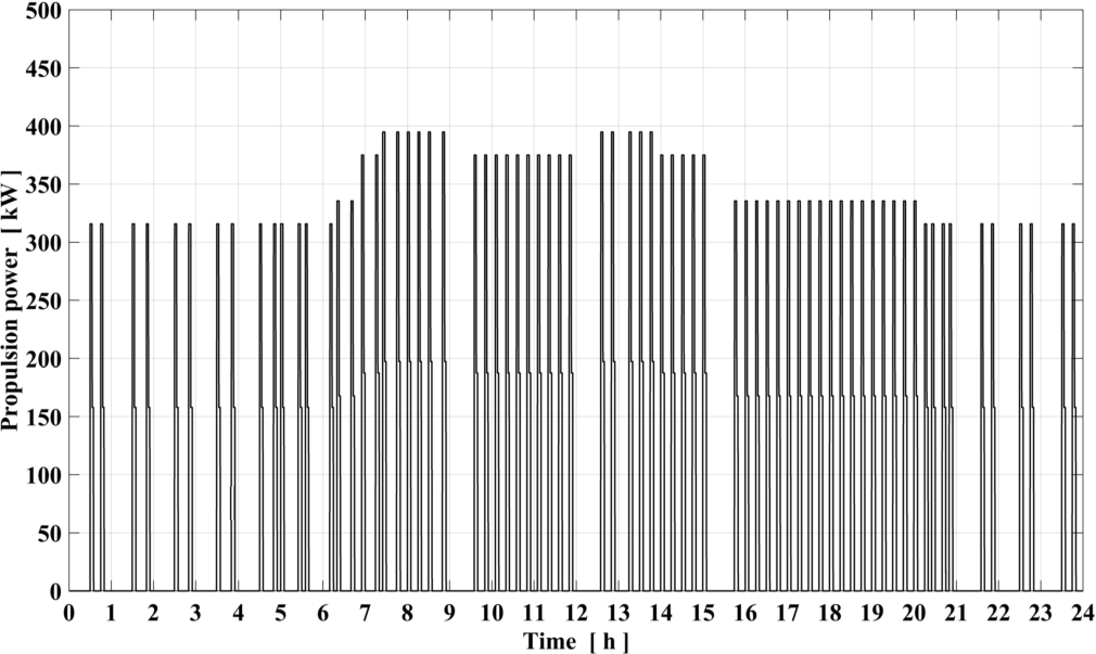
Fig. 6.
Cumulative daily propulsion and auxiliary power.
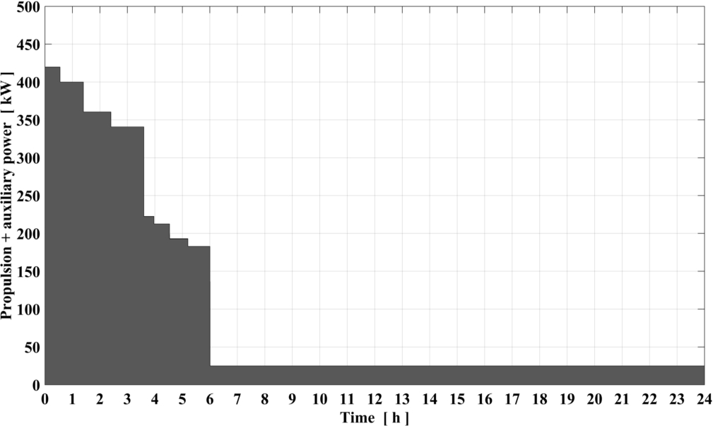
As shown in Figure 6, for most of the time the ship is at harbour and requires only the auxiliary power.
FCs cover the average power demand, while batteries serve as peak shaving. Batteries can be partially charged by the fuel cells during the stopping time of the ferry.
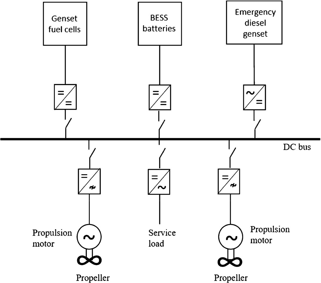
Figure 7 shows a simple schematic of the chosen electric plant. FCs rack and battery pack are connected to separate DC/DC converters to increase the system flexibility and efficiency. The choice of DC bus is not a common practice in the maritime field, but allows an efficient connection of FCs, energy storage system and utilities [20].
Fig. 7.
Schematic of hybrid power system layout for the proposed case study.
In order to assess the fuel required to run the ferry for a typical day of operation an energy simulation model has been implemented on the basis of the following assumption:
the power required to maintain design speed when the ferry is fully loaded is 395 kW (peak hours operation) otherwise it is 315 kW. Sailing time is considered to be 5 min at two power levels (Figure 5);
auxiliary power demand is assumed to be 25 kW, constant during the whole day;
propulsion engines are switched off when the ship is moored;
global electric efficiency of the power conditioning system is considered to be 95%.
Simulation results show that the base load to be supplied by the FCs, to satisfy the overall 24 h ship energy demand, is approximately of 95 kW. Choosing a commercial fuel cell stack of 120 kW, the efficiency of fuel cells based on Lower Heating Value (LHV) of hydrogen results to be 49%, and the quantity of hydrogen for a typical day of operation is approximately 140 kg.
From the analysis of the simulation model results, the BESS should be designed in order to satisfy the following conditions:
energy storage capacity: 340 kWh, assuming a Depth Of Discharge (DOD) of 80% and a maximum State of Charge (SOC) of 90%;
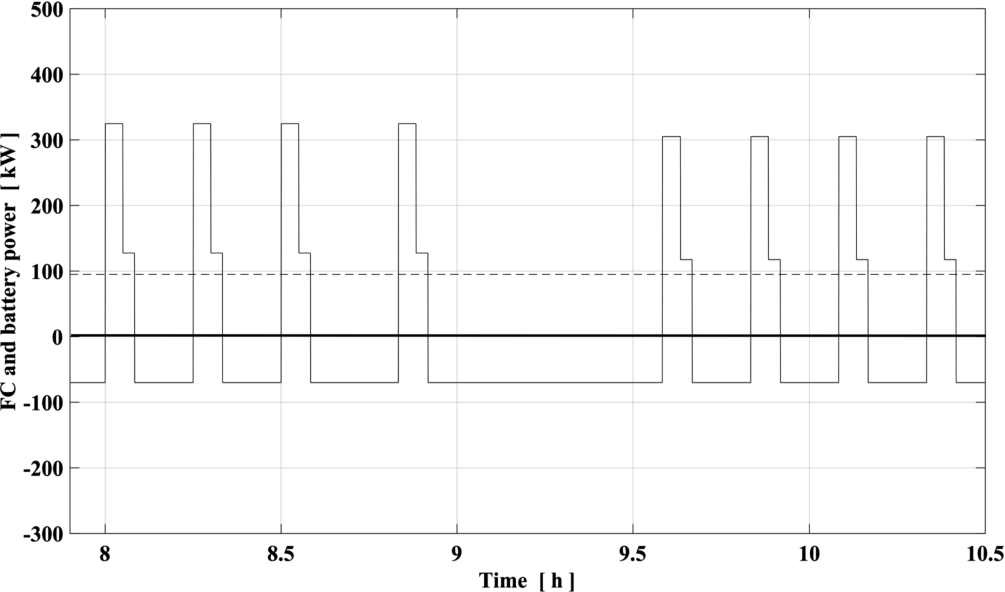
Figure 8 reports the SOC of batteries during the day while Figure 9 shows the synergic operation of FCs and batteries for power supply. Residual charge at the end of the day is the same considered at the beginning of the day. Limitation on the maximum SOC is in accordance with common practices to reduce degradation of Li-ion batteries [55].
Fig. 8.
State of charge of batteries during the day.
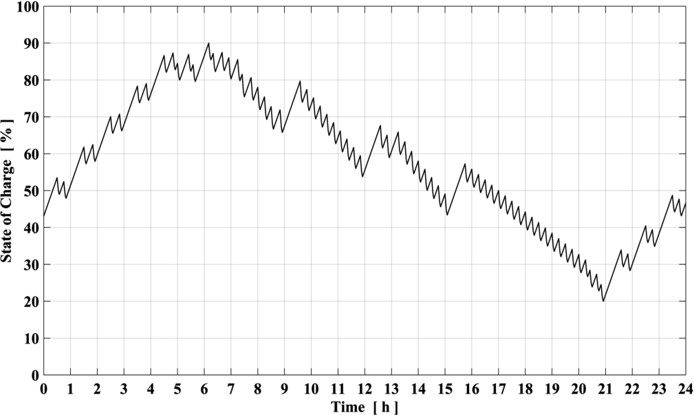
Fig. 9.
Instantaneous fuel cells and batteries power supply for the ferry considered in the case study. Solid line: battery power (charging power if negative). Dashed line: fuel cells power.
3.1.Hydrogen tank
It was chosen to calculate the volume required for compressed hydrogen storage on board of the vessel using both the Type I cylinder at 250 bar (the safest and cheapest hydrogen solution to date) and the innovative cylinder developed in the GASVESSEL® project at 300 bar.
Table 5 reports storage data for both GASVESSEL® and Type I solutions at 300 bar (one single cylinder) and 250 bar (66 cylinders) respectively, with reference to the 140 kg of hydrogen required for one day of operation. Storage temperature is assumed to be 25°C.
Table 5
Pressure vessel characteristics to store 140 kg of hydrogen at 25°C. GASVESSEL® and Type I [8] cylinders are considered
| Type of cylinders | Hydrogen weight [kg] | Pressure of cylinders [bar] | Water volume single cylinder [m3] | Cylinders outer volume [m3] | Number of cylinders [–] | Storage system weight [ton] |
| GASVESSEL® | 140 | 300 | 6.81 | 8.0 | 1 | 1.8 |
| Type I | 140 | 250 | 0.12 | 9.9 | 66 | 8.9 |
For Type I cylinders, even if larger water volumes are available on the market, a 120 l water capacity has been chosen due to the higher flexibility in terms of on board arrangement.
The final volume of the storage system should take into account for the temperature reached by the hydrogen during the refilling process. Depending on the loading process, the hydrogen temperature could be higher than the ambient temperature. Therefore, the loaded hydrogen mass could be lower than expected (“under filling problem” [24]).
This problem will be discussed in the next paragraph.
3.2.Filling process analysis
The filling of pressure vessel is a complex operation and several issues have to be considered. Among these there are the power and the energy required for the process, the filling time, the gas pressure and flow rate time profile and the “under filling” problem. To analyze these issues and to allow to optimize the filling procedure a specific process simulation model has been implemented within the GASVESSEL® project. The simulation model is hereafter used to assess the tank volume required for the ferry taking into account the under filling problem and to calculate the time required for the filling.
The cylinder on board of the ship is considered to be refilled using an on shore storage tank. Also the latter is a GASVESSEL® cylinder at 300 bar of pressure, designed in order to fit in a 40 feet container.
Starting from the condition of empty on board cylinder, i.e. with internal pressure equal to the minimum value necessary to feed the FCs, the loading process starts with a first free loading phase, during which the filling takes place by pressure difference with respect to that of the on shore storage cylinder.
When the pressure difference drops, and the mass flow rate becomes too small, the process continues with a second forced loading phase, during which a compressor provides the complete filling at the predefined final pressure value (300 bar).
A cooler between the compressor and the cylinder allows to increase the loaded mass of hydrogen.
The main features of the simulation model are described hereafter.
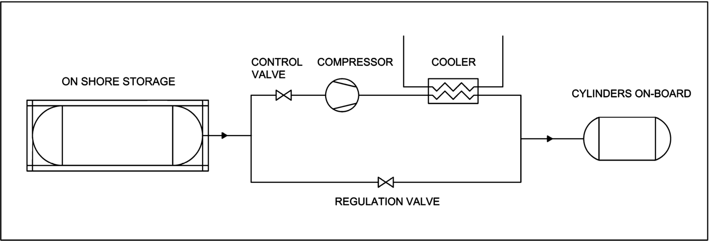
The fuel system is considered to be composed of two horizontal cylindrical tanks of different size and pressure, connected by a duct with a regulation valve. A compressor, with its control valves, is installed in parallel with the duct (Figure 10). The duct diameter is obtained according to the prescriptions of the NORSOK STANDARD P-001 in order to limit the gas speed in the pipe [42].
Fig. 10.
Schematic of the proposed refuelling system using two GASVESSEL® cylinders, one off board and one on board.
The potential energy linked to any difference in altitude among the system components is not taken into account. Inside each tank, the kinetic energy of the gas is neglected and the time-dependent gas pressure and temperature are uniform, as well as the wall temperature. The ducts are modelled assuming one-dimensional flow with uniform gas properties. Friction forces per unit length are calculated by means of the Darcy factor derived from the Moody diagram.
The values of the model variables are obtained by applying the usual conservation laws of mass, momentum and energy. The mass flow rate during the free loading phase is calculated as an isenthalpic expansion through an orifice, in subsonic or chocked conditions. During the following forced loading phase, the mass flow rate is obtained finding the intersection of the time dependent resistant characteristic curve of the circuit with the operating characteristic curves of the compressor. The hydrogen properties are calculated with the Coolprop® libraries.
The following assumptions have been made:
maximum pressure of the on board cylinder: 300 bar;
minimum pressure of the on board cylinder: 5 bar;
volume of the on shore storage cylinder: 41.8 m3;
initial pressure of the on shore storage cylinder: 300 bar;
temperature at the beginning of the loading process: 25°C, in equilibrium with the surrounding environment, for both the cylinders;
wall temperature of the on board cylinder obtained taking into account the free convection heat exchange with ambient air;
single stage 100 kW positive displacement compressor.
Table 6
Simulation results for the filling process of the on board cylinder. Cases A to D refer to the different volumes of on board cylinder considered for the simulations
| Refuelling n° | Case | On-board cylinder water volume [m3] | Hydrogen final temperature [°C] | Wall final temperature [°C] | Loading time [min] | Loaded mass [kg] |
| 1 | A | 6.80 | 140.2 | 122.0 | 20 | 106 |
| B | 8.15 | 137.0 | 119.2 | 24 | 128 | |
| C | 9.71 | 133.7 | 116.5 | 29 | 153 | |
| D | 10.66 | 131.6 | 114.9 | 32 | 167 | |
| 2 | A | 6.80 | 139.6 | 121.4 | 20 | 106 |
| B | 8.15 | 136.7 | 119.0 | 25 | 127 | |
| C | 9.71 | 134.3 | 117.0 | 31 | 153 | |
| D | 10.66 | 132.9 | 115.6 | 35 | 168 | |
| 3 | A | 6.80 | 140.9 | 122.5 | 22 | 105 |
| B | 8.15 | 139.0 | 120.7 | 28 | 127 | |
| C | 9.71 | 137.1 | 119.4 | 35 | 151 | |
| D | 10.66 | 135.9 | 118.4 | 41 | 166 | |
| 4 | A | 6.80 | 142.8 | 124.1 | 24 | 105 |
| B | 8.15 | 140.7 | 122.4 | 32 | 126 | |
| C | 9.71 | 137.9 | 120.0 | 46 | 151 | |
| D | 10.66 | 134.5 | 117.2 | 60 | 167 | |
| 5 | A | 6.80 | 143.8 | 125.0 | 28 | 105 |
| B | 8.15 | 140.1 | 121.9 | 42 | 126 | |
| C | 9.71 | 126.2 | 110.1 | 87 | 151 | |
| D | 10.66 | 113.0 | 98.7 | 96 | 128 | |
| 6 | A | 6.80 | 143.2 | 124.4 | 35 | 104 |
| B | 8.15 | 129.3 | 112.7 | 76 | 128 | |
| C | 9.71 | 93.7 | 81.9 | 96 | 76 | |
| D | 10.66 | – | – | – | – |
Simulations are ran for different volumes of the on board cylinder, starting from the theoretical value necessary to store 140 kg at 300 bar and 25°C. Table 6 and Table 7 report the obtained results with reference to the on board cylinder and the storage cylinder respectively. It must be noted the very high temperatures reached by hydrogen in the on board cylinder during the filling process that can reach 130°C. This leads to two problems: loss of mechanical properties of the epoxy resin in the GASVESSEL® tank and the previously mentioned under filling issue.
Table 7
Simulation results for the on shore storage tank. Cases A to D refer to the different volumes of on board cylinder considered for the simulations
| Refuelling n° | Case | Storage tank final pressure [bar] | Storage tank final temperature [°C] | Storage tank residual mass [kg] | Storage tank pressure at 25°C [bar] |
| 1 | A | 242.0 | 7.3 | 756 | 257.9 |
| B | 230.7 | 3.6 | 734 | 249.3 | |
| C | 218.1 | −0.8 | 709 | 239.5 | |
| D | 210.8 | −3.4 | 695 | 233.8 | |
| 2 | A | 202.8 | 5.3 | 653 | 217.7 |
| B | 184.8 | 0.7 | 610 | 201.2 | |
| C | 164.3 | −5.2 | 561 | 183.3 | |
| D | 153.0 | −8.9 | 531 | 172.5 | |
| 3 | A | 165.8 | 2.8 | 550 | 179.6 |
| B | 141.5 | −3.5 | 487 | 156.9 | |
| C | 114.6 | −11.7 | 413 | 131.1 | |
| D | 99.4 | −17.2 | 370 | 116.2 | |
| 4 | A | 130.5 | −0.5 | 448 | 143.1 |
| B | 101.0 | −9.4 | 364 | 114.4 | |
| C | 69.0 | −22.0 | 266 | 81.7 | |
| D | 51.7 | −29.9 | 207 | 63.0 | |
| 5 | A | 97.1 | −5.7 | 346 | 108.4 |
| B | 63.2 | −18.4 | 242 | 75.3 | |
| C | 29.4 | −27.9 | 119 | 35.6 | |
| D | 21.2 | −21.5 | 84 | – | |
| 6 | A | 65.4 | −12.9 | 244 | – |
| B | 30.0 | −24.9 | 121 | – | |
| C | 12.7 | −4.1 | 47 | – | |
| D | – | – | – | – |
As for the first problem, the wall temperature could affect the mechanical resistance of the cylinder. Therefore, temperature sensors must be incorporated in the cylinder wall, as proposed in [24] and [30]. In order to control the wall temperature, different solutions can be implemented, such as gas cooling, cylinder walls cooling and/or filling time extension.
As for the under filling problem, due to the heating of the hydrogen, at the end of a loading process the density of the gas is lower than that at ambient temperature. In order to analyze and overcome the under filling problem, in the following, several hydrogen tank volumes are considered. In Table 6 and Table 7 the different volumes are referred to as cases A, B, C and D.
The under filling analysis shows that to store the required mass of hydrogen (140 kg) it is necessary to increase the water volume of the cylinder from 6.81 m3 to 9.71 m3 (case C of Table 6 and Table 7). This corresponds to an external cylinder volume of 11.4 m3 and a weight of 2.5 ton. Considering the space utilization factor of the GASVESSEL cylinder (approximately 75%), the total volume required by the containment system on board would be 15.2 m3.
Results of the under filling analysis for the solution with Type I cylinders at 250 bar show that 94 tanks would be needed, instead of the 66 reported in Table 5. This would result in a total volume of 14.0 m3 and a weight of 12.3 ton. Considering a space utilization factor of 50%, as reported in [19], the total volume required by the containment system on board would be 28 m3.
Table 6 and Table 7 also show that with the considered on shore storage tank it is possible to complete five refuellings of the on board cylinder. Up to the fourth refuelling, the maximum required compression ratio is 4.4, but at the end of the fifth refuel it increases up to 10. This is a quite high value for a single stage positive displacement compressor and, therefore, a two-stage arrangement should be preferred.
Figure 11 to Figure 14 show pressure and hydrogen temperature in both cylinders during the first and the fifth refueling. Figure 13 and Figure 14 show also the wall temperature of the on board cylinder. Figure 15 Figure 16 report the corresponding hydrogen mass flow rates.
Fig. 11.
Pressure of the cylinders during the first loading process. On board cylinder water volume: 9.71 m3. Solid line: on board cylinder; dashed line: storage cylinder.
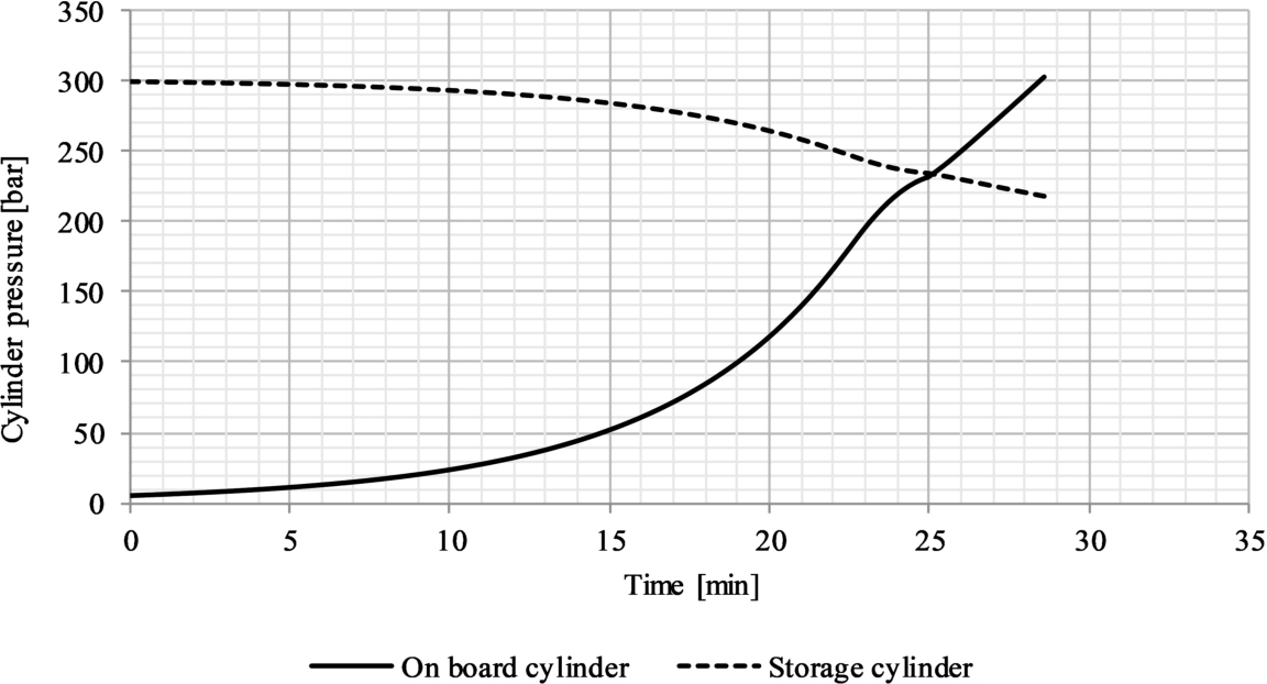
Fig. 12.
Pressure of the cylinders during the fifth loading process. On board cylinder water volume: 9.71 m3. Solid line: on board cylinder; dashed line: storage cylinder.
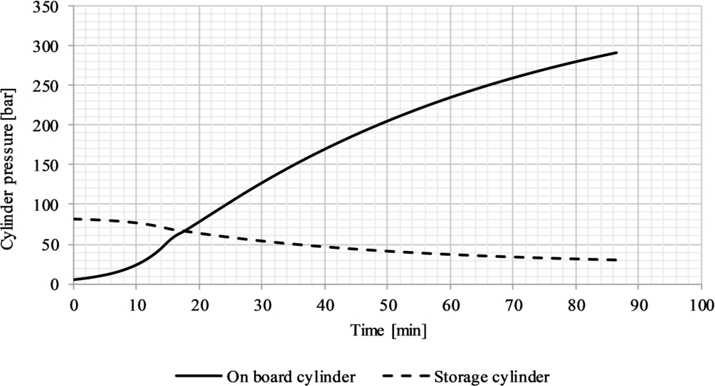
Fig. 13.
First loading process: temperature of hydrogen in both cylinders and wall temperature of the on board cylinder. On board cylinder water volume: 9.71 m3. Solid line: on board cylinder hydrogen temperature; dotted line: on board cylinder wall temperature; dashed line: storage cylinder hydrogen temperature.
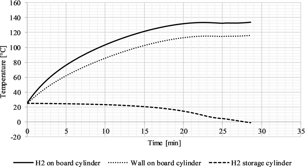
Fig. 14.
Fifth loading process: temperature of hydrogen in both cylinders and wall temperature of the on board cylinder. On board cylinder water volume: 9.71 m3. Solid line: on board cylinder hydrogen temperature; dotted line: on board cylinder wall temperature; dashed line: storage cylinder hydrogen temperature.
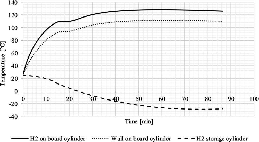
Fig. 15.
Mass flow rate of hydrogen during the first loading process. On board cylinder water volume: 9.71 m3.
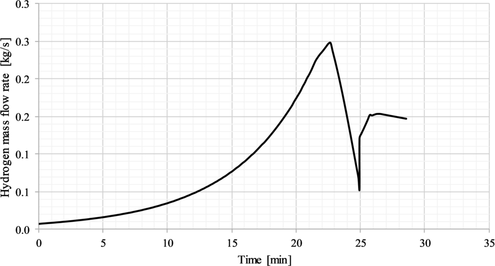
Fig. 16.
Mass flow rate of hydrogen during the fifth loading process. On board cylinder water volume: 9.71 m3.
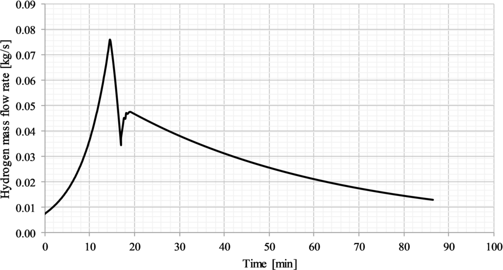
The first phase of the refilling takes place by pressure difference between the two cylinders (see Figure 11 and Figure 12). The gas flow rate is determined by the opening of the regulation valve, which maintains the gas velocity in the pipes at the maximum value allowed according to [42]. In this phase, the increasing density of the gas in the downstream duct causes the increase of the flow rate shown in Figure 15 and Figure 16, until the pressure difference between the on shore storage and the on-board cylinder is sufficiently high. When the pressure difference becomes low, the flow rate decreases steeply and the compressor starts, continuing the loading phase until the pressure reaches 300 bar in the on-board cylinder.
4.Conclusions
Hydrogen storage is still one of issues that hampers the possibility to develop ship propulsion system with zero local emissions. Many studies have the aim to increase the containment pressure and/or volume in order to improve the energy density of compressed gas: one of these is the Compressed Natural Gas Transport System (GASVESSEL®) EU funded project. The aim of the project is to develop cylinders that, potentially, could contain compressed hydrogen with an energy density, both in terms of mass and weight, of about the half that of LH2. This energy density is higher than that of the current types of cylinders.
In this paper, this type of new pressure vessel is employed for hydrogen storage in a small ferry. In particular, a process simulation model has been implemented to assess the quantity of hydrogen that can be stored on board, taking into account boundary conditions such as filling time and cylinder wall temperature.
The model is applied to a case study that considers the retrofit a small size RoRo passenger ferry with a HPS based on PEM fuel cells and Li-ion batteries, fuelled by compressed hydrogen stored in a one single cylinder. The retrofit covers both auxiliary and propulsion energy demand during the day, requiring 140 kg of hydrogen for one day of operation and about 340 kWh of elecricity storage capacity (batteries).
The model allows to assess the temperature time profiles of the hydrogen and of the cylinder wall during the filling process. With these data it was possible to infer the storage volume in order to load the cylinder with the required mass of hydrogen taking into account the temperature increase during the filling process and the cylinder heat loss. At a storage pressure of 300 bar the outer volume of the cylinder is 11.4 m3 with a total weight of 2.5 ton. Considering the space utilization factor of GASVESSEL cylinders (75%), the total volume required by the storage system on board would be 15.2 m3. By comparison, with Type I cylinders at their typical pressure of 250 bar and 50% of space utilization factor, the total volume required by the storage system would be 28.0 m3 and the weight 12.3 ton.
Even if the innovative type of pressure cylinder allows to reach an energy density higher than conventional intermediate pressure cylinders, the volume necessary to store a quantity of energy typical for the shipping sector is many times higher than that required by conventional fuels today used. Moreover, the bunkering infrastructure for gaseous fuel remains bulky and fuel logistic can be complex. The analysis points out, as expected, that the filling process is critical to maximize the stored hydrogen mass and that it is critical to measure the temperature of the cylinder walls in order not to exceed the material limits. Nevertheless, for specific applications such as the one considered in the paper, the introduction of gaseous hydrogen as fuel, can be considered for implementing zero local emission propulsion systems in the medium term.
Acknowledgements
The project has received funding from the European Union’s Horizon 2020 research and innovation programme under grant agreement No 723030.
A special thanks to Dr. Enrico Vianello and Ph.D. Nicola Zuliani for their help in the definition and analysis of the case study.
References
[1] | http://ec.europa.eu/environment/life/project/Projects/index.cfm?fuseaction=home.showFile&rep=file&fil=Zemships_Brochure_EN.pdf, accessed on October 2019. |
[2] | http://ngvtechnology.com/type-2.html, accessed on March 2020. |
[3] | http://www.faber-italy.com/eng-product-, accessed on March 2020. |
[4] | https://spbes.com/, accessed on March 2020. |
[5] | https://worthingtonindustries.com/getmedia/26ed37f0-590c-4666-99b7-fce44f40c59c/Hydrogen-Type-3-Spec-sheet_040717_web.pdf?ext=.pdf, accessed on March 2020. |
[6] | https://www.carnivalcorp.com/news-releases/news-release-details/carnival-corporations-aidanova-first-ship-be-supplied-lng, accessed on March 2020. |
[7] | |
[8] | https://www.cp-industries.com/downloads/pdf/technical/Type%201%20NGV2%20Tank%20Designs.pdf, accessed on March 2020. |
[9] | https://www.gasvessel.eu/wp-content/uploads/2018/06/D2.1-Scenario-Description-and-Characterization.pdf, accessed on March 2020. |
[10] | https://www.hexagonlincoln.com/resources/brochures, accessed March 2020. |
[11] | https://www.hydrogenics.com/, accessed on October 2019. |
[12] | https://www.ship-technology.com/projects/hydrogenesis-passenger-ferry/, accessed on September 2019. |
[13] | |
[14] | P.T. Aakko-Saksa, C. Cook, J. Kiviaho and T. Repo, Liquid organic hydrogen carriers for transportation and storing of renewable energy – review and discussion, Journal of Power Sources 396: ((2018) ), 803–823. doi:10.1016/j.jpowsour.2018.04.011. |
[15] | F. Baldi, S. Moret, K. Tammi and F. Maréchal, The role of solid oxide fuel cells in future ship energy systems, Energy 194: ((2020) ), 116811. doi:10.1016/j.energy.2019.116811. |
[16] | H. Bathélémy, Hydrogen storage-industrial prospective, International Journal of Hydrogen Energy 37: ((2012) ), 17364–17372. doi:10.1016/j.ijhydene.2012.04.121. |
[17] | H. Bathélémy, M. Weber and F. Barbier, Hydrogen storage: Recent improvements and industrial perspectives, International Journal of Hydrogen Energy 42: ((2017) ), 7254–7262. doi:10.1016/j.ijhydene.2016.03.178. |
[18] | F. Burel, R. Taccani and N. Zuliani, Improving sustainability of maritime transport through utilization of Liquefied Natural Gas (LNG) for propulsion, Energy 57: ((2013) ), 412–420. doi:10.1016/j.energy.2013.05.002. |
[19] | F. Cadenaro and E. Fort, Alternative Fuels: Present and Future of Containment Technologies and Impact on Shipbuilding, Technology and Science for the Ships of the Future, IOS Press, (2018) . |
[20] | S. Castellan, R. Menis, A. Tessarolo, F. Luise and T. Mazzuca, A review of power electronics equipment for all-electric ship MVDC power systems, International Journal of Electrical Power and Energy Systems 96: ((2018) ), 306–323. |
[21] | C.H. Choi, S. Yu, I.-S. Han, B. Kho, D. Kang et al., Development and demonstration of PEM fuel-cell-battery hybrid system for propulsion of tourist boat, International Journal of Hydrogen Energy 41: ((2016) ), 3591–3599. doi:10.1016/j.ijhydene.2015.12.186. |
[22] | CMR prototech plans first hydrogen ferry in Norway, with fuel cells, Fuel Cells Bulletin 5 (2016) 3. |
[23] | N. de Vries, Safe and effective application of ammonia as a marine fuel, Master thesis in Marine Technology, Delft University of Technology (2019). |
[24] | C.J.B. Dicken and W. Mérida, Measured effects of filling time and initial mass on the temperature distribution within a hydrogen cylinder during refueling, Journal of Power Sources 165: ((2007) ), 324–336. doi:10.1016/j.jpowsour.2006.11.077. |
[25] | DNV GL statistics, https://afi.dnvgl.com/Statistics?repId=1, accessed on March 2020. |
[26] | DNV-GL, Assessment of selected alternative fuels and technologies, June 2019. |
[27] | DNV-GL, Study on the use of fuel cells in shipping, (EMSA), Report, 2017. |
[28] | U. Eberle, M. Felferhoff and F. Schuth, Chemical and physical solutions for hydrogen storage, Angewandte Chemie, Int. Ed. 48: ((2009) ), 6608–6630. doi:10.1002/anie.200806293. |
[29] | FellowSHIP project wraps up maritime battery, fuel cell R&D, Fuel Cell Bulletin 9 (2018). |
[30] | M.C. Galassi, B. Acosta-Iborra, D. Baraldi, C. Bonato, F. Harskamp et al., Onboard compressed hydrogen storage: Fast filling experiments and results, Energy Procedia 29: ((2012) ), 192–200. doi:10.1016/j.egypro.2012.09.024. |
[31] | GASVESSEL® project, https://www.gasvessel.eu/about/, accessed on October 2019. |
[32] | German e4ships project reports on fuel cell maritime demos, Fuel Cells Bulletin 10 (2016) p5. |
[33] | Hydrogen hybrid ferry under construction for New York service, Fuel Cells Bulletin 1 (2011) 5-6. |
[34] | ILK Dresden, Moritz Kuhn [CC BY-SA 4.0 (https://creativecommons.org/licenses/by-sa/4.0)], accessed on November 2019. |
[35] | IMO. IGF CODE International code of safety for ships using gases or other low-flashpoint fuels. |
[36] | International Maritime Organization, Initial IMO strategy on reduction of GHG emissions from ships, Annex 11, Resolution MEPC.304(72), 2018. |
[37] | D.R. Johnson, R. Heltzel, A.C. Nix, N. Clark and M. Darzi, Greenhouse gas emissions and fuel efficiency of in-use high horsepower diesel, dual fuel, and natural gas engines for unconventional well development, Applied Energy 206: ((2017) ), 739–750. doi:10.1016/j.apenergy.2017.08.234. |
[38] | L.E. Klebanoff, J.W. Pratt, C.M. Leffers, K.T. Sonerholm, T. Escher, J. Burgard et al., Comparison of the greenhouse gas and criteria pollutant emissions from the SF-BREEZE high-speed fuel cell ferry with a diesel ferry, Transportation Research Part D 54: ((2017) ), 250–268. doi:10.1016/j.trd.2017.05.012. |
[39] | M. Li, Y. Bai, C. Zhang, Y. Song, S. Jiang et al., Review on the research of hydrogen storage system fast refuelling in fuel cell vehicle, International Journal of Hydrogen Energy 44: ((2019) ), 10677–10693. doi:10.1016/j.ijhydene.2019.02.208. |
[40] | J.W. Makepeace, T. He, C. Weidenthaler, T.R. Jensen, F. Chang, T. Vegge et al., Reversible ammonia-based and liquid organic hydrogen carriers for high-density hydrogen storage, International Journal of Hydrogen Energy 44: ((2019) ), 7746–7767. doi:10.1016/j.ijhydene.2019.01.144. |
[41] | Marine traffic, https://www.marinetraffic.com, accessed on 10/10/2019. |
[42] | Norwegian Technology Center: Norsok Standard Process System P100, 2001. |
[43] | Now, voyager? The increasing marine use of fuel cells, Fuel Cells Bulletin 5 (2010), 12-17. |
[44] | R.P. O’Hayre, S.W. Cha, W. Colella and F.B. Prinz, Fuel Cell Fundamentals, John Wiley and Sons, New York, (2006) . |
[45] | B.G. Pollet, S.S. Kocha and I. Staffell, Current status of automotive fuel cells for sustainable transport, Current opinion in Electrochemistry 16: ((2019) ), 90–95. doi:10.1016/j.coelec.2019.04.021. |
[46] | Prevention of Air Pollution from Ships, IMO website, http://www.imo.org/en/OurWork/environment/pollutionprevention/airpollution/pages/air-pollution.aspx, accessed on 15/10/2019. |
[47] | M. Rivarolo, D. Rattazzi and L. Magistri, Best operative strategy for energy management of a cruise ship employing different distributed generation technologies, International Journal of Hydrogen Energy 43: ((2018) ), 23500–23510. doi:10.1016/j.ijhydene.2018.10.217. |
[48] | A.B. Smith, Gas fuelled ships: Fundamentals, benefits classification & operational issues, in: Proceedings of the First Gas Fuelled Ships Conference, Hamburg, Germany, (2010) . |
[49] | S. Specchia, G. Saracco and V. Specchia, Modeling of an APU system based on MCFC, International Journal of Hydrogen Energy 33: (13) ((2008) ), 3393–3401. doi:10.1016/j.ijhydene.2008.03.066. |
[50] | D. Stolten and B. Emonts, Hydrogen Science and Engineering: Materials, Processes, Systems and Technology, Wiley-VCH Verlag GmbH&Co. KGaA, (2016) . |
[51] | Third IMO GHG study 2014 – Executive summary and final report, International Maritime Organization (2015). |
[52] | S. Ushakov, D. Stenersen and P.M. Einang, Methane slip from gas fueled ships: A comprehensive summary based on measurement data, Journal of Marine Science and Technology 24: ((2019) ), 1308–1325. doi:10.1007/s00773-018-00622-z. |
[53] | L. Van Biert, M. Godjevac, K. Visser and P.V. Aravind, A review of fuel cell systems for maritime applications, Journal of Power Sources 327: ((2016) ), 345–364. doi:10.1016/j.jpowsour.2016.07.007. |
[54] | Wartsila marine SOFC for Wallenius car-carrier, Fuel cells bulletin 6 (2010) 1. |
[55] | Woody, M. Arbabzadeh, G.M. Lewis, G.A. Koleian and A. Stefanopoulou, Strategies to limit degradation and mazimize Li-ion battery lifetime – critical review and guidance for stakeholders, Journal of Energy Sources 28: ((2020) ), 101–231. |
[56] | WSFlox Reformer, “Compact C1, technical datasheet”, WS Reformer GmbH, Dornierstraße 14, D-71272 Renningen, Germany (2008). |
[57] | I. Yamamoto, T. Aoki, S. Tsukioka, H. Yoshida, T. Hyakudome, Sawa et al., Fuel cell system of AUV Urashima, in: Ocean ’04 – MTS/IEEE Techno-Ocean ’04: Bridges Across the Oceans – Conference Proceedings, Vol. 3: , (2004) , pp. 1732–1737. doi:10.1109/OCEANS.2004.1406386. |
[58] | Z. Zhou, M.B. Camara and B. Dakyo, Coordinated power control of variable-speed diesel generators and lithium-battery on a hybrid electric boat, IEEE Transactions on Vehicular Technology 66: (7) ((2017) ). |


