
Maritime fuel cell applications: A tool for conceptual decision making
Abstract
The environmental impact of ships needs to be reduced by using more sustainable and cleaner solutions for power generation on board to meet the increasing amount of regulations. Fuel cells are seen as one of the most promising solutions to address this challenge. There are various fuel cell technologies which can be combined with different fuel types, resulting in a large number of options. In order to find the best prospect, a review of the fuel and fuel cell technologies is performed to get an understanding of the possibilities and applicability of fuel cells on superyachts.
Various systems were compared on the following characteristics: density, storage type, maturity, safety, and emissions. Based on these characteristics a decision-making tool was developed to assist in the decision-making process considering of many variables. Using this tool, it has become clear that a fuel cell solution should be specifically selected for any different type of application. The required applications or required usage of a fuel cell could lead to the selection of a completely different type of technology.
1.Introduction
Over the past years more and more attention is given to the reduction of greenhouse gasses in order to lower the impact on health and environment. Governments and international organisations are setting stricter regulations and targets regarding emissions and pollution on land and sea [13,14,16]. The emissions of ships need to be reduced by using more sustainable and cleaner solutions in the near future to meet these regulations.
Fuel cells have existed for almost 200 years [2], but the technology has never really broken through and is only used in certain niche market. However, fuel cells have undergone rapid developments recent years, largely due to substantial investments from the automotive and household industries [6,11]. As a consequence, the maritime industry is becoming increasingly interested in the technique, particularly as it is seen as a promising solution to drastically reduce the environmental impact of ships.
Fuel cells have the potential to be highly efficient, reaching electrical efficiencies up to 65% [1,7], far surpassing that of a combustion engine with efficiencies between 35–45% [34]. Fuel cells generate electrical energy via an electrochemical reaction rather than the combustion process of a diesel engine, thus resulting in less noise and vibrations. Therefore, the level of comfort on board is improved in addition to a lower environmental impact, making the solution even more attractive for the application to superyachts.
There are a number of fuel cell solutions which can be combined with different types of fuels, yielding a large pool of options, each having its own characteristics. Many articles discuss the characteristics and development of fuel cells and fuels. However, little has been written about what type of technology is recommended for different applications, or when there is a tipping point where one technique becomes more appropriate than the other.
Since there are numerous factors which should be taken into account when selecting a fuel cell solution, it is difficult to make a well-motivated choice. Therefore, a tool was developed to provide a helping hand by supporting and accelerating the decision-making process. The decision-making tool generates the most promising fuel cell solutions based on specific characteristics, thus reflecting the design choices for an energy generation system.
2.Fuel cell systems
Although the emphasis of this paper is on the conceptual decision-making tool, the fuel cell itself is an important part of this as a whole and certainly cannot be omitted. However, since the target of this paper is to clarify the structure and reasoning behind the tool rather than an extensive literature study, the current market status presented solely represents the interpretation of the authors. This is based on a separate, and more extensive internal market study of which some interesting overviews and conclusions are shared. Therefore, a short fuel cell market development analyses is given after which the most interesting techniques for maritime applications are highlighted.
2.1.Market development
![Annual unit shipments per fuel cell type (data source: [6,11]).](https://content.iospress.com:443/media/isp/2020/67-1/isp-67-1-isp190275/isp-67-isp190275-g001.jpg)
![Megawatts by fuel cell type (data source: [6,11]).](https://content.iospress.com:443/media/isp/2020/67-1/isp-67-1-isp190275/isp-67-isp190275-g002.jpg)
There is a range of fuel cell technologies available at the moment, all with their own characteristics. An overview of the market is given based on the annual shipments and the annual produced amount of fuel cell megawatts by fuel cell type and applications of commercially available fuel cells for the years 2009–2017 [6,11] (Figs 1, 2).
– The PEMFC (Proton Exchange Membrane Fuel Cell) is the most produced type of fuel cell and experienced the most rapid growth rates. PEMFC usually refers to low temperature PEMFC (LT-PEMFC), but there is also a high temperature variant (HT-PEMFC). Only one manufacturer currently produces the HT-PEMFC in the form of a “complete commercial product”, and only in a limited volume. They do not appear in the market overviews as these numbers are too low, hence the PEMFC in the market development overview only covers the LT-PEMFC. During the last couple of years the shipment growth of these low temperature cells has flattened, whilst the annual produced amount of power grew extensively, showing that the amount of power per fuel cell has increased over the years. This is largely due to the automotive investments in this technology (LT-PEMFC), Toyota, Honda and Hyundai together represent approximately 75% of the 455 MW fuel cells shipped in the transport sector,11 the +/−3000 vehicles account for approximately 350 MW [11].
– The SOFCs (Solid Oxide Fuel Cells) have experienced an opposite development compared to the LT-PEMFC, the annual amounts of shipped SOFC’s grew faster than the annual power. This indicates a decrease in power per shipped fuel cell, which can be explained by the development in small powered CHP22 SOFC’s for household usage with low power requirements [11]. The number of MCFC (Molten Carbonate Fuel Cell) shipments are very limited compared to both the LT-PEMFC and SOFC while the amount of megawatt for this type of fuel cell is roughly the same as seen with the SOFC fuel cell. This can be explained by the fact that the MCFC is mainly used for large land-based power plants. This same story also applies to PAFC (Phosphoric Acid Fuel Cell) [7].
– DMFC (Direct Methanol Fuel Cell) is typically used for small electronic devices like phones, laptops, camera’s, etc (with powers in the range of 1W–1kW) [7,11]. This is the reason for a relatively large number of DMFC shipments annually while there is a very low amount of total combined power.
– AFC (Alkaline Fuel Cell) is only used for special applications, this is due to its limited lifetime and the requirement of very pure hydrogen and oxygen [32]. For this reason, the annual shipments and produced megawatts for this type of fuel cell are negligible.
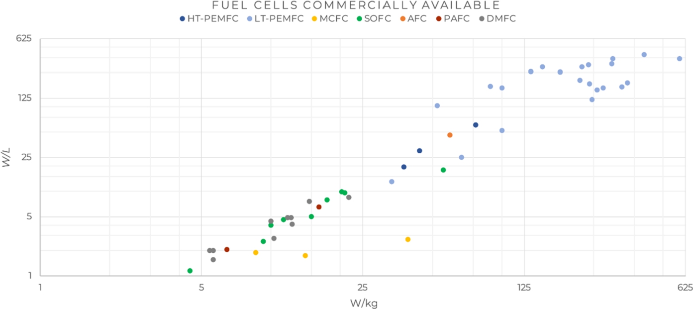
In addition to the broad view of the fuel cell market, an overview of fuel cell techniques and manufacturers is shown in Fig. 3, showing the power densities of fuel cell systems currently available on the market. This analysis illustrates the difference in density between fuel cell technologies. A large distribution between the energy density of fuel cells of the same type is noticed (varying due to: fuel cell size, sector, manufacturer, etc.).
Fig. 3.
Power densities of fuel cell systems currently available on the market (logarithmic scale).
2.2.Most promising fuel cells for the maritime industry
The last two decades have seen an increased interest in fuel cell technology from the maritime sector. At least 23 projects were carried out in this period, which are almost exclusively demonstrator cases [32]. Most of these projects make use of PEMFC technology, while some projects are using the SOFC and MCFC technology but in a much smaller extent. It can be concluded that the types of fuel cells used in the maritime sector show approximately the same trend as seen with the global fuel cell market.
Based on market research the most promising fuel cells for usage within the maritime sector are selected, in total seven different types of fuel cells are compared [7,17,27,32,34]. The main decision drivers on which the fuel cells are assessed are: power density, power levels, efficiency, fuel sensitivity/poison, start-up time/ cycling capabilities and usable waste heat (CHP). Each fuel cell is ranked for these factors with a:
Table 1
Comparison of different fuel cell technologies
| Low temperature | Medium temperature | High temperature | |||||
| LT-PEMFC | DMFC | AFC | HT-PEMFC | PAFC | MCFC | SOFC | |
| Power density: | + | + | − | +/− | |||
| Power levels: | − | − | |||||
| Electrical efficiency: | + | − | |||||
| Fuel sensitivity/poison: | − | − | + | + | |||
| Start-up time/ cycling | + | − | +/ | ||||
| Usable waste heat: | + | + | |||||
| Maturity:4 | + | − | / | + | |||
| Total score: | |||||||
3 The start-up time and life cycle capabilities of a SOFC depends on the type of SOFC technology.
4 Maturity is based on number of projects in the maritime sector and total number of shipments.
Fuel cells are often categorised based on their operating temperature, this comparison shows that for each category one type of fuel cell technology clearly stands out in terms of score. The most promising fuel cell types are: LT-PEMFC for the low temperature fuel cells, the HT-PEMFC for the medium temperature fuel cells and the SOFC for the high temperature fuel cells.
3.Fuel for fuel cells
Most fuel cells operate on a hydrogen or hydrogen rich gas, with the exception of high temperature fuel cells, which can use fuels like methanol, methane or ammonia directly. This section gives an overview of different types of hydrogen storage, as well as other storage mediums which can be used to store hydrogen indirectly and the associated needed processes to extract the hydrogen. Hydrogen storage is divided in three sections: physical based, fuel based and material based hydrogen storage.
3.1.Storage solutions
3.1.1.Physical based hydrogen storage
Physical based hydrogen is a type of storage which stores hydrogen in its pure form. Hydrogen is the lightest and most abundant chemical in the universe. It has the second lowest boiling and melting point of all substances, helium is the only element which has a lower boiling and melting point [5].
Hydrogen is a colour- and odourless gas at ambient conditions with a very low flash point temperature of −253°C [10]. Hydrogen scores high in terms of gravimetric density because of its low weight (33.3 kWh/kg [3]). On the other hand, the volumetric density of hydrogen is very low, the density of hydrogen at ambient conditions is 0.08 kg/m3 [10] compared to 1.2 kg/m3 [31] for air. The low volumetric density makes it impractical to store hydrogen at ambient condition. Therefore, pure hydrogen is typically stored in a compressed or liquid state to increase the volumetric density.
3.1.2.Fuel based hydrogen storage
Storing hydrogen in its pure form is not a very energy dense solution with respect to the volume, even if it is stored at high pressure or cryogenic temperature. Hydrocarbon fuels provide a more dense alternative that can be used as fuel either directly in some types of fuel cells, or in most of the cases by implementing a fuel reforming process in advance of the fuel cell to purify the fuel to a hydrogen rich gas. Different hydrogen containing fuels can be used, such as: Methanol, Ethanol, DME, LNG and Diesel.
For all fuel based solutions some kind of fuel reforming is required, either internal (in case of high temperature fuel cells) or external (for low temperature fuel cells) and sometimes a combination of both for difficult re-formable fuels. The goal of reforming is to process a fuel containing hydrogen into a hydrogen rich gas which can be used in a fuel cell.
Fig. 4.
Fuel processing steps.
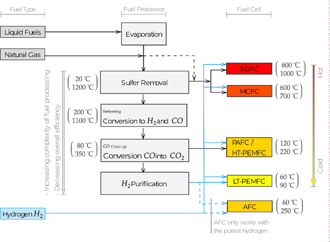
A general overview of the fuel processing steps needed to process various types of fuels in combination with different types of fuel cells is given in Fig. 4. In this diagram the fuel cells on the right are ranked from high temperature (top) to low temperature (bottom), which simultaneously orders them according to the required purity of the fuel. It is important to keep in mind that every step adds to the complexity of the system and will reduce the overall efficiency since almost all reforming steps require energy. In general, it can be said that the lower a solution is located in the diagram the lower the efficiency will be with simultaneously increasing complexity [7,27,28].
3.1.3.Material based hydrogen storage
The last type of storage makes use of a carrier material which can be used for bonding hydrogen atoms. The carrier can be ‘charged’ and ‘discharged’ of hydrogen with this type of storage method. When the hydrogen is released from the carrying material it offers pure hydrogen which can directly be used in almost any fuel cell type. Examples of material based hydrogen storage are: Liquid Organic Hydrogen Carriers (LOHC) and Metal Hydrides (such as Sodium Borohydride and AB-5-type alloys).
3.2.Other aspects to consider for marine integration
Several other aspects of the different fuels are to be considered for maritime applications. A basic overview of these aspects is given in Table 2.
Table 2
Basic overview of the fuel safety aspects
| State of matter under normal conditions | |
| Gaseous fuels: | Ammonia, DME, LNG, Hydrogen |
| Liquid fuels: | Methanol, Ethanol, MGO, LOHC, Formic Acid |
| Dry fuels: | Sodium Borohydride, Metal Hydride |
| Flashpoint conditions | |
| Above 60°C: | Ammonia, MGO, LOHC, Metal Hydride (Sodium Borohydride), Metal Hydride (AB-5-type alloy) |
| Below 60°C: | Methanol, Ethanol, DME, LNG, Hydrogen, Formic Acid |
| Material incompatibility | |
| Aluminium: | Formic Acid |
| Carbon steel: | Formic Acid |
Storage and regulations are important factors for the integration of machines in maritime applications. Certain fuels cannot be stored in the double bottom due to their specific pressure storage requirements i.e. compressed or liquid hydrogen. Using a fuel which cannot be stored within the double bottom has a significant disadvantage, because the impact on the design of a yacht will be substantially larger than with fuels which can be placed within the double bottom.
The regulations regarding fuel for ships state that fuels used on board should have a minimum flash point temperature of 60°C, with exception of fuels for emergency generators and lifeboats (SOLAS Convention [15]). For fuels with a flash point lower than 60°C, the International Code of Safety for Ship Using Gases or Other Low-flashpoint Fuels (IGF code) [30] has to be followed. Currently, the IGF covers only natural gas (LNG). The next version of the IGF will introduce additional regulations for methanol and ethanol, as well as rules for fuel cells.
Some of the fuels compatible with fuel cells have a lower flash point than 60°C, which causes some concerns regarding storage and use on board. Even though regulations are not yet in place, additional safety measures will have to be considered, i.e. additional ventilation of spaces where fuel is stored, passes through and is consumed, as well as the application of all double walled pipes for the fuel system. For now, these aspects need to be discussed with the Classification Society on a case-by-case approach.
The power generation system on board of a yacht has to endure load variations depending on the yachts usage and location. Fuel cells are usually not capable of following rapid load changes. Especially high temperature fuel cells have a relatively low ramp-up/down response. Therefore, fuel cell applications typically should be coupled with batteries or another electrical energy storage system to overcome this. The batteries could also be used to reduce the installed fuel cell power, improve lifetime of fuel cells, and improve the fuel cell efficiency. The size of the battery pack dependents on the operational profile, type of fuel cell, and the intention of the battery hybrid system.
4.Conceptual decision-making tool
Now the options for fuel cells and fuels are known, it is important to determine which of these combinations have the best potential to be used in a ship design. The choice of fuel and fuel cell combination affects many different factors and can vary from project to project. Since several factors are to be considered and weighted in order to arrive at a considered choice, a decision-making tool is created with the aim to make the decision-making process for fuel and fuel cell easier.
4.1.Idea and methodology of the tool
The goal of the tool was to get insight into the different fuel cell and fuel combinations and find an optimal fuel cell solution during a conceptual decision-making phase. Users can use this tool for supporting and accelerating the decision/selection process when looking for a fuel cell and fuel combination.
The tool is based on a multi-criteria analysis to distinguish between different fuel and fuel cell combinations, where the most important characteristics are compared based on certain decision criteria. The decision criteria used in this tool are: overall density, storage type, maturity, safety and emission which will be discussed below.
The values for the decision criteria (
The criteria are provided with a weighting factor, which can be altered based on the requirements/targets of the project/user. The overall result is calculated for the sum product of the weight factors (
The variables which can be changed are the time (continuous operating hours between refuelling) and the weight factors (
Finally, the different solutions can be ranked on the scores, which will generate the list of solutions sorted from best to worst. The result can be used to compare the applicability of the technique for the operation that is envisaged.
4.1.1.Overall density
One of the most important factors is the density of the system. The type of fuel in combination with the type of fuel cell determines the necessity and quantity of any type of fuel reforming and thereby influences the overall density of the system. Therefore, it is key to not only look at the fuel and fuel cell separately but as a whole.
The densities of the combined fuel cell and fuel storage system are used to calculate the effective density which is used to draw a Ragone chart for comparing the different combined solutions.
The market study (Fig. 3) showed a large spread in the density between models and/or manufacturers of the same fuel cell technique, this could cause differences in the results of the Ragone charts. The most power dense solutions currently available on the market were used to calculate the overall densities.
![Energy storage solution, volumetric density comparison [4,8–10,18–21,23,24,33].](https://content.iospress.com:443/media/isp/2020/67-1/isp-67-1-isp190275/isp-67-isp190275-g005.jpg)
![Energy storage solutions, gravimetric density comparison [4,8–10,18–21,23,24,33].](https://content.iospress.com:443/media/isp/2020/67-1/isp-67-1-isp190275/isp-67-isp190275-g006.jpg)
All mentioned fuels have been compared on both volumetric (Fig. 5) and gravimetric density (Fig. 6) and are plotted together in a graph to easily compare the density of the different fuels. For both densities55 the pure fuel without a storage system and the fuel including a storage system are shown in the two graphs. A distinction is made between fuels which can be stored in a conventional steel tank66 and fuels which need to be stored in a special tank for the fuel including storage system. Special tanks are needed for the storage of pressurised or cryogenic fuels. For the fuels which can be stored in conventional tanks, a factor to estimate the weight and volume of a tank according to S.C. Misra [22] is used to determine the density including storage system. MGO, Methanol, Ethanol, Formic Acid and LOHC are liquid fuels under ambient conditions and can be stored in approximately the same kind of tanks as used for diesel, while all other fuels need a special storage system. The density of these storage systems are based on actual commercially available storage systems, the impact of these tanks on the overall density of the fuel is shown in Figs 5 and 6.
Effective density. The effective power (
Since this overview should give an indication of the density of the total system the power density (P) and efficiency (η) is the combination of both the fuel cell and fuel processing system (Eq. (6) and (7)).
To check this formulation the limits of the
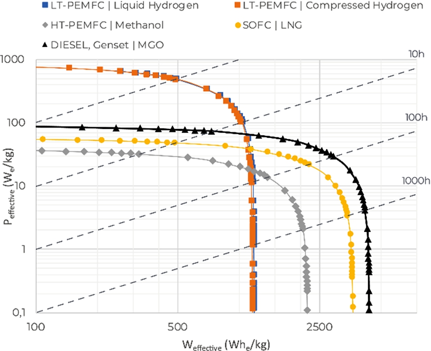
Ragone chart. A Ragone chart is a commonly used type of plot to make a performance comparison of different energy storing devices. With this type of chart the effective energy density (Wh/kg or Wh/L) is plotted versus the effective power density (W/kg or W/L) on a logarithmic scale. In this case the effective densities are used to generate the Ragone chart. A Ragone chart for both the volumetric and gravimetric density are shown in Figs 7 and 8 for several fuel cell and fuel combinations in reference to a diesel engine running on MGO.
Fig. 7.
Ragone chart, volumetric density.
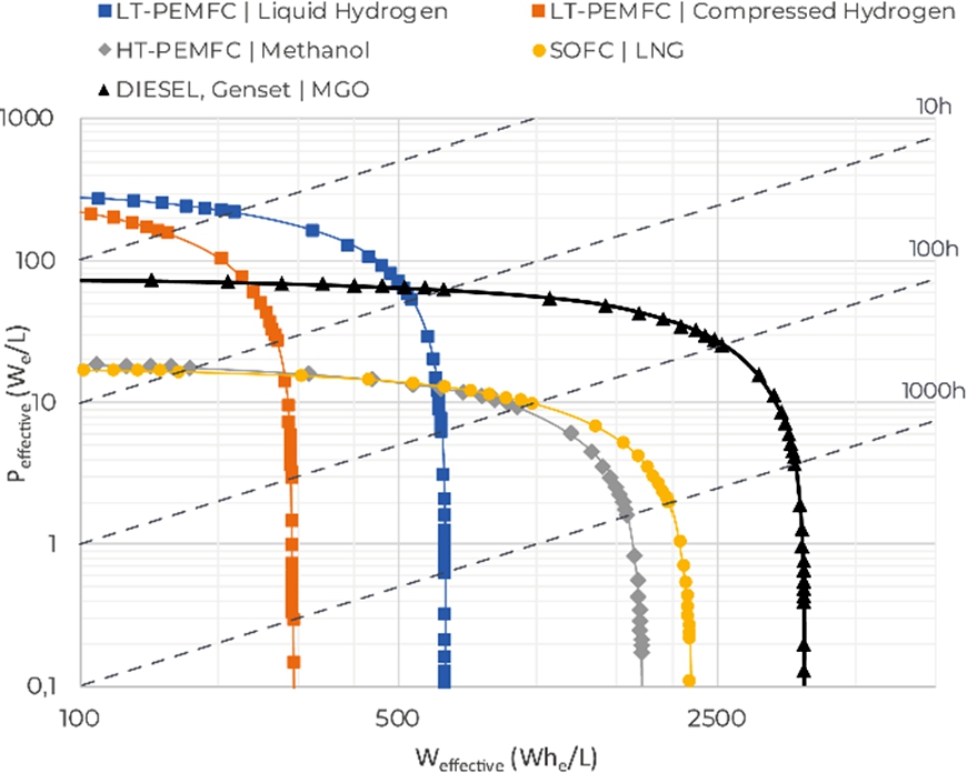
Fig. 8.
Ragone chart, gravimetric density.
The two values
From the Ragone chart it can be concluded that there is no single solution that is optimal for a wide range of applications, as is the case with diesel combustion engines. For fuel cells, there are different optimal technological solutions for different operating times. From the two Ragone example diagrams it’s visible that the MGO powered diesel engine (reference) is in nearly all the cases the most energy dense solution. For projects which do not require to be operational for more than a few hours without having to fuel in between, the low temperature fuel cells can offer a more energy dense solution then a diesel engine. When energy converters are compared on the energy density, fuel cells at the moment only seems to be a viable solutions for ships which require a short range and can be refuelled easily, for example: ferries, inland ships or yacht which are used as day boats.
Both the effective volumetric and effective gravimetric densities are taken into account in the tools as decision criteria. As the effective density varies with the expected operation time of the system, the time – factor (t) is implemented as a variable in the tool.
4.1.2.Storage type
The type of storage is seen as an important criteria factor for selecting the type of fuel, therefore it was decided to have separate decision criteria for the type of storage, despite the fact that storage is already included within the density.
Diesel fuel is generally stored inside the double bottom for the current yachts of Oceanco, therefore the amount of space and weight which needs to be added for the construction of tanks is kept to a minimum. Fuel that can be stored in this same location would have the same benefits as well. Fuels that cannot be placed in the double bottom tank have to be placed in another location which is used for other purposes, typically luxury space. For this reason a distinction is made between a fuel which could be stored in the conventional double bottom tank and a fuel where this is not possible. It is assumed that all fuels which are in liquid or powder state under ambient conditions can be stored in the double bottom. These fuels are: MGO, Ethanol, Methanol, Metal Hydrides (Sodium Borohydride), Formic acid and LOHC.
4.1.3.Maturity
The maturity of a fuel and/or fuel cell technology is regarded as an important criteria, since this influences to what extent such a technique can or cannot be readily applied. The technological readiness level (TRL) is used to determine the maturity of the different technologies. The TRL system was developed by NASA in the 1970’s and has since been used by various institutes. In total there are nine different levels used in the TRL system: the first three levels are used for the discovery phase, level 4–6 represent the development phase, level 7–8 are used for projects that have made it to the demonstration phase and lastly level 9 is used for projects that are actually deployed. The TRL status is determined for all different fuel and fuel cell combinations [25].
Next to the TRLs, the existence of relevant companies is taken into account as an additional factor to assess the maturity status of the different fuel and fuel cell combinations. This is done by introducing four different distinction levels: active company for the marine sector (1), active manufacturer in another sector (0.75), active company in the past/ very limited activity (0.25) and lastly no active company (0). For the maturity level, the tool uses the TRL status, which is corrected for the level of company activity with the values mentioned in parentheses.
4.1.4.Safety
As mentioned before, the SOLAS convention addresses the safety requirements assuming that fuels are to have a flash point temperature of at least 60°C, for fuels with lower flash point temperatures the IGF code has to be followed. Due to these regulations the flash point temperature is one of the safety factors which needs to be considered. Besides the flash point temperature, which covers the fire hazards, other factors should be considered concerning safety: health hazards, environmental hazards, instability hazards and chemical compatibility with materials.
The basic health, fire and instability hazards are all covered in a systematic way by the NFPA 704. This is a standard system of the National Fire Protection Association of the U.S. where hazards are indicated with a number from 0-4, where 0 is a minimal hazard and 4 is a severe hazard [12,26]. This hazard indication system is used as a base in the tool to score the importance of health, fire and instability hazards for the different fuels.
4.1.5.Emissions
Emission reduction in shipping is one of the main drivers why fuel cells are considered, therefore the emissions of different fuels are an important decision criteria.
Carbon dioxide emissions are defined to be the most harmful for the environment with respect to greenhouse gasses. Next to the carbon emissions there are also other harmful emissions (e.g. NOx and SOx) and for which regulations are becoming increasingly strict.
When a fuel cell is fuelled with hydrogen the fuel cell operates completely emission free, as a fuel cell then only emits heat and water. Other fuels like Ammonia (NH3) or LNG can contain sulphur or nitrogen which can result in NOx or SOx emissions. Sulphur is poisonous for all types of fuel cells, therefore any sulphur traces should be removed in advance. Nitrogen oxides (NOx) are typically formed by the reaction of nitrogen and oxygen under high temperatures in the form of NO. All types of fuel cells and fuel reformers practically operate below the temperature where NOx or only limited NOx will be formed. Therefore, the emissions of NOx and SOx by a fuel cell are not taken into account in the tool.
The amount of CO2 emissions is considered to be of influence when selecting a solution. In this respect only the operational emissions are taken into account in the tool. The mass ratio of carbon dioxide can be obtained using Eq. (8) [29].
This mass ratio gives the amount of CO2 per kilogram fuel. Together with the energy density of the fuel, the amount of CO2 emission per kilowatt hour of fuel can be calculated. An overview of the CO2 emissions for the different discussed fuels are shown in Table 3.
Table 3
Total overview of CO2 emissions per type of fuel
| MGO | LNG | Methanol | Ethanol | DME | Formic Acid | Hydrogen | Ammonia | LOHC | Metal Hydride (Sodium Borohydride) | Metal Hydride (AB-5-type alloy) | |
| Emission (gCO2/kWhfuel) | 262.9 | 230 | 246.1 | 255.2 | 242.2 | 622.3 | 0 | 0 | 0 | 0 | 0 |
For hydrogen carriers and fuels that do not contain any carbon no CO2 will be emitted. These fuels or carriers are: Hydrogen (compressed or liquefied), Ammonia (NH3), LOHC, Metal Hydride (Sodium Borohydride and AB-5-type alloy).
Next to the emissions on board the ship itself, the production and supply of the fuel requires energy as well and therefore contributes to the life cycle emissions of a yacht. This aspect is not covered in the emission criteria nor is it related to a specific amount of CO2 emissions in the tool. It is however, incorporated in the defined fuel options: i.e. grey hydrogen vs green hydrogen.
For various designs different criteria can be more or less important, therefore a weight factor is added to all decision criteria. These weight factors are implemented as variables within the decision matrix so that the weight factors can be entered by the preference of the user, by changing the weight factors certain important characteristics for the design can be emphasised.
4.2.Demonstration of the tool
The decision-making tool is demonstrated with three different example cases to illustrate how the tool could be used and to demonstrate the importance of selecting a fuel cell system on a case by case approach.
4.2.1.Examples for different application
Case 1: Fast passenger ferry (short range). Distance: 25 nm | Speed: 20 kn | Continuous sailing time: 1.2 h
Explanation of weight factors: For a fast sailing vessel weight is an important factor, volume however is in this case of less importance because this passenger ferry only has to transport people for a short time so a seat per person should do the job.
Case 2: Super yacht (medium range). Distance: 5000 nm | Speed: 14 kn | Continuous sailing time: 357 h
Explanation of weight factors: For a yacht the biggest selling point is the luxury space, this should be maximised therefore the volume density is very important. Weight is also quite important since yachts are generally designed for high maximum speeds. The fuel is always stored in the double bottom, so a fuel which could be stored in the double bottom is preferable.
Case 3: Bulk carrier (long range). Distance: 12300 nm | Speed: 12 kn | Continuous sailing time: 1025 h
Explanation of weight factors: Volume density is important since the payload needs to be maximised as the money will be earned here. As the speed is relatively low and the ship is transporting heavy goods the weight is not seen as an important factor. Storage type is important from the volume point of view because this can save space for cargo.
4.2.2.Input variables
The input variables are coupled to the requirements/targets of the project and are therefore influenced by the user’s assessment. The input variables used for the example cases (shown in Table 4) are used only for demonstration. The reasoning behind the input values of weight, volume, and storage type has been explained in the example cases.
Table 4
Input of variables for decision making tool for the different example cases
| Weight factors | ||||||||||
| Weight density (w1) | Volume density (w2) | Storage type (w3) | Maturity (w4) | Overall safety (w5) | Fire hazard7 (s1) | Health hazard7 (s2) | Instability7 (s3) | Emission (w6) | Time factor [h] | |
| Case 1. Fast ferry | 4 | 1 | 0 | 1 | 2 | 1 | 1 | 1 | 3 | 1.25 |
| Case 2. Superyacht | 1.5 | 3 | 1.5 | 1 | 2 | 1 | 1 | 1 | 3 | 357 |
| Case 3. Bulk carrier | 1 | 4 | 2 | 1 | 2 | 1 | 1 | 1 | 3 | 1025 |
7 Internal safety weight factor, this factor only affects the weight of the different safety hazards within the used weight factor for safety. The overall weight safety factor is leading.
The emission weight factor is the same for all cases and is set to a relatively high value, since the reduction of emission is the main reason to look into the possibilities of fuel cells. The internal weight factors of the different safety categories vary from 1 to 3 indicating the importance of the different type of hazards, however the overall weight factor is determined by the safety factor and is set the same for all cases. Maturity is set to one (1) for all cases, indicating the importance of the technology being reasonably developed, while not adding extra complexity for comparing between the cases. Lowering the weight factor of maturity gives the possibility to compare ‘future’ solutions with currently available solutions.
4.2.3.Results
The top ten results for all three cases are shown in Fig. 10, the most important conclusions are mentioned below.
Example case 1: only LT-PEM fuel cells with different types of fuels are been brought forward in the top ten results. For this type of ship the following fuels are the most promising options in combination with a LT-PEMFC: Liquid hydrogen, Compressed hydrogen, LOHC, Formic Acid (renewable) and metal hydride (AB-5-type alloy).
For the other two examples the HT-PEMFC and SOFC become increasingly attractive, since the sailing time increases. For longer continuous operating times these types of fuel cells in combination with energy dense hydrocarbon fuels will be more energy dense.
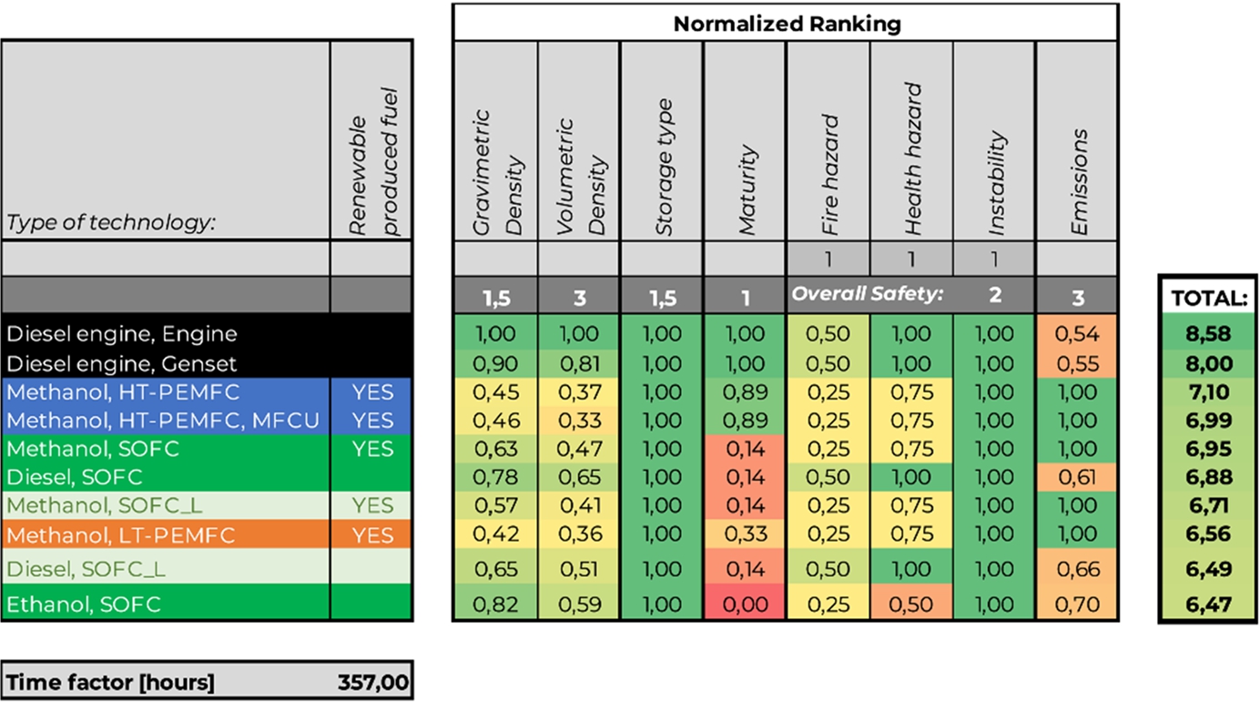
For example case 2: all different types of fuels cells end up within a relatively small difference in score. The methanol HT-PEMFC’s and SOFC in combination with methanol or diesel are very close and are the most promising. Further a LT-PEMFC could be interesting in combination with methanol. For this specific example case a snapshot of the decision tool including the normalised decision criteria is shown in Fig. 9 for the top ten results.
Fig. 9.
Decision making tool, top 10 results (diesel engines are mentioned in the tool for reference) example case 2.
The best options for the last case only consist of methanol HT-PEMFC and SOFC’s in combination with diesel, methanol or ethanol.
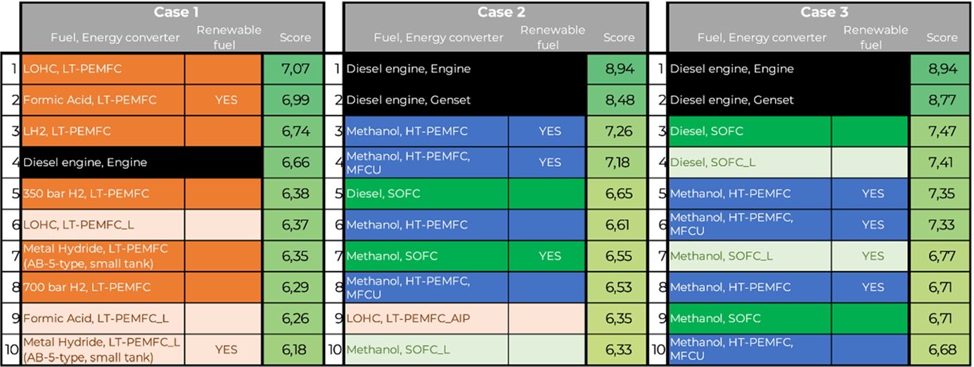
Next to the defined weight factors, the results were checked with a sensitivity analysis. During this sensitivity analysis the criteria weight factors are varied with 700 random values between 0 and 1 while keeping a constant time factor. These random values are then used to calculate the total scoring, with this approach the result should be independent of any personal or project orientated preference. The 700 different scores are compared based on the: geometric mean, average and median scores. These three scores all showed the same result, therefore only an overview of the median is shown in Fig. 11. Comparing the calculated scores with the sensitivity analyses (Fig. 10 and Fig. 11) shows that the weight factors have an impact on the results. However, this only has a limited impact on the top ten results. In each case, the same types of fuels and fuel cells appear in the top ten results. There are some small changes in the order of the results and in some cases changes in the type of technology. Since the impact of the weight factors is relatively limited in these example cases, it can be concluded that the results offer a robust solution since largely the same is found for a more average approach. However, the results of the sensitivity analysis cannot be used as optimal solution for all applications. When there are large outliers in the chosen weighing factors, this will have a large impact on the results and will result in bigger deviations.
Fig. 10.
Decision making tool, top 10 results example cases.
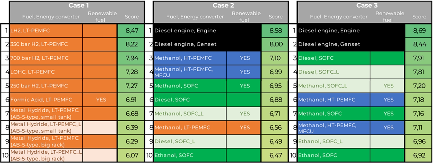
Fig. 11.
Decision making tool, sensitivity analysis.
5.Conclusion
Various fuel cell systems including different fuels were compared on the following characteristics: density, storage type, maturity, safety, and emissions. Based on these characteristics a decision-making tool was developed to assist in the decision-making process considering of many variables. The tool can be used as guidance to make an early assessment to find the best fuel cell solution for a particular case. The assessment is made based on the preferences of the user regarding the fuel cell system characteristics including the fuel and required time range of the yacht.
Specific preferences for a system can be specified by changing the weighting factor for the decision criteria. The order of all options will be rearranged by the tool when changing the weight factors, showing the ranking of the most promising solutions corresponding to the preferences of the user. The tool reveals that a fuel cell solution should be specifically selected for each specific application. A different application or operational profile could lead to the selection of a completely different type of technology. This is in contrast with traditional propulsion systems, were a diesel combustion engine is generally used for the power generation on board and only an appropriate size needs to be selected.
6.Recommendations
The focus of the tool is to make a selection based on technical feasibility. Cost and future perspectives are not included in the development of the tool. These aspects are not incorporated since these values are still difficult to obtain at the moment and the differences in maturity and production scale can give a distorted picture. It is recommended to add these aspects or other criteria (i.e. impact of regulations) once available.
The tool is intended for use in the conceptual design phase. For this assessment, the system density is based on time (effective volumetric and effective gravimetric energy densities), providing the optimal solution independent of the required power. The next step would be a design study revealing to what extent fuel cells can be used for power generation giving the constraints of the design (e.g. propulsion or only small auxiliary power).
The time variable is considered to have the biggest influence on the results, far more than the other variables (the weight factors). These criteria can be used according to the preference of the user. If some criteria are less important during an assessment, the weight factor could simply be set to zero which ensures that this criterion is not included in the overall scoring.
Notes
1 Shipped in the year 2016.
2 Combined heat and power, also called cogeneration.
5 The fuel densities are based on the lower heating value.
6 Possibly with coating or build from stainless steel when the fuel is not chemical compatible.
References
[1] | Bloom Energy, Energy server 5, es5-ya8aan, https://www.bloomenergy.com/sites/default/files/es5-300kw-datasheet-2019.pdf, last accessed 6 February 2019. |
[2] | A. Boudghene Stambouli and E. Traversa, Fuel cells, an alternative to standard sources of energy, Renewable and Sustainable Energy Reviews 6: ((2002) ), 297–306. |
[3] | B. Boundy, S.W. Diegel, L. Wright and S.C. Davis, Biomass energy data book, appendix a: Lower and higher heating values of gas, liquid and solid fuels, Technical report, U.S. Department of Energy, 2011. |
[4] | B. Boundy, S.W. Diegel, L. Wright and S.C. Davis, Biomass energy data book, appendix a: Lower and higher heating values of gas, liquid and solid fuels, Technical report, U.S. Department of Energy, 2011. |
[5] | R. Carriveau and D. Ting, Hydrogen storage and compression, in: Methane and Hydrogen for Energy Storage, The Institution of Engineering and Technology, London, (2016) . doi:10.1049/PBPO101E. |
[6] | D. Carter and W. Jonathan, The fuel cell industry review 2013, Technical report, FuelCellToday, 2013. |
[7] | EG&G Technical Services, Inc., Fuel Cell Handbook, 7th edn, National Technical Information Service, U.S. Department of Commerce, Springfield, VA, (2014) . |
[8] | Engineering ToolBox, Fuel gases heating values, 2015, https://www.engineeringtoolbox.com/heating-values-fuel-gases-d_823.html, last accessed 20 March 2019. |
[9] | A. Godula-Jopek, W. Jehle and J. Wellnitz, Hydrogen Storage Technologies: New Materials, Transport, and Infrastructure, Wiley-VCH Verlag GmbH & Co. KGaA, Weinheim, Germany, (2012) . |
[10] | H2Tools, Basic hydrogen properties, n.d., https://h2tools.org/hyarc/hydrogen-data/basic-hydrogen-properties, last accessed 25 March 2019. |
[11] | D. Hart, F. Lehner, R. Rose, J. Lewis and M. Klippenstein, The fuel cell industry review 2017, Technical report, E4tech, 2017. |
[12] | A.M. Helmenstine, What is NFPA 704 or the fire diamond?, 2019, https://www.thoughtco.com/what-is-nfpa-704-or-the-fire-diamond-609000, last accessed 24 March 2019. |
[13] | IMO, Energy efficiency measures, 2018, http://www.imo.org/en/OurWork/Environment/PollutionPrevention/AirPollution/Pages/Technical-and-Operational-Measures.aspx, last accessed 8 January 2019. |
[14] | IMO, UN body adopts climate change strategy for shipping, 2018, http://www.imo.org/en/MediaCentre/PressBriefings/Pages/06GHGinitialstrategy.aspx, last accessed 8 January 2019. |
[15] | International Maritime Organization. Maritime Safety Committee, SOLAS: International Convention for the Safety of Life at Sea, 1974: 1996 amendments, effective July 1998, International Maritime Organization, 1998. |
[16] | M. Launes, Norwegian parliament adopts zero-emission regulations in the fjords, 2018, https://maritimecleantech.no/2018/05/03/norwegian-parliament-adopts-zero-emission-regulations-fjords/, last accessed 8 January 2019. |
[17] | Z. Liu, Fuel Cell Performance, Nova Science Publishers, Inc., (2012) . |
[18] | A. Lundgren and A. Wachsmann, The potential of methanol as a competitive marine fuel, Technical report, Chalmer, 2011. |
[19] | MABANAFT, Net calorific value & gross calorific value, 2015, https://www.mabanaft.com/en/news-info/glossary/details/term/calorific-value.html, last accessed 20 March 2019. |
[20] | MAN Diesel & Turbo, Product specification, vacuum insulated tanks, n.d., https://sweden.man-es.com/docs/librariesprovider16/cryo-files/6-2-product-specification-vacuum-insulated-tank.pdf?sfvrsn=bd7fda2_2, last accessed 19 March 2019. |
[21] | MAN energy solutions, HFO, n.d., https://powerplants.man-es.com/fuels/hfo, last accessed 20 March 2019. |
[22] | S.C. Misra, Design Principles of Ships and Marine Structures, CRC Press, (2015) . |
[23] | N/A, Metal hydride hydrogen storage for H2 fuel cells, n.d., http://www.hbank.com.tw/fc/fpe.html, last accessed 4 April 2019. |
[24] | N/A, Gas tanks for anhydrous ammonia, n.d., http://www.eurotainer.com/containers/products-list/gas-tanks-for-anhydrous-ammonia, last accessed 25 April 2019. |
[25] | N/A, Horizon 2020 – Work programme 2014–2015 anex G. Technology readiness levels (TRL), 2020, https://ec.europa.eu/research/participants/data/ref/h2020/wp/2014_2015/annexes/h2020-wp1415-annex-g-trl_en.pdf, last accessed 13 May 2019. |
[26] | N/A, Hydrogenious-technology, n.d., https://www.hydrogenious.net/, last accessed 4 April 2019. |
[27] | R.P. O’Hayre, S.-W. Cha, W.G. Colella and F.B. Prinz, Fuel Cell Fundamentals, 3rd edn, Wiley, Hoboken, NJ, (2016) . |
[28] | D. Shekhawat, J.J. Spivey and D.A. Berry, Fuel Cells: Technologies for Fuel Processing, Elsevier, (2011) . |
[29] | D. Stapersma, Diesel Engines, Volume 3: Combustion, NLDA & Delft UT, (2010) . |
[30] | Sub-Committee on Carriage of Cargoes and Containers, CCC 5, agenda items 3 and 8, Technical report, IMO, 2018. |
[31] | The Engineering ToolBox, Air – Density, specific weight and thermal expansion coefficient at varying temperature and constant pressures, n.d., https://www.engineeringtoolbox.com/air-density-specific-weight-d_600.html, last accessed 25 March 2019. |
[32] | T. Tronstad, H.H. Åstrand, G.P. Haugom and L. Langfeldt, EMSA study on the use of fuel cells in shipping, Technical report, DNV-GL, 2017. |
[33] | A. Valera-Medina, H. Xiao, M. Owen-Jones, W.I.F. David and P.J. Bowena, Ammonia for power, Progress in Energy and Combustion Science 69: (69) ((2018) ), 63–102. doi:10.1016/j.pecs.2018.07.001. |
[34] | L. van Biert, M. Godjevac, K. Visser and A. Purushothaman Vellayani, A review of fuel cell systems for maritime applications, Journal of Power Sources 327: ((2016) ), 345–364. doi:10.1016/j.jpowsour.2016.07.007. |


