
Quantitative evaluation of capsular and labral resistances in the hip joint using a probing device
Abstract
BACKGROUND:
Probing to assess conditions of hip capsule and acetabular labrum is performed by “surgeons’ feeling”.
OBJECTIVE:
We investigated the resistance of the labrum and the hip capsule quantitatively while they were pulled with a probing device.
METHODS:
With the probing device in which a strain gauge was embedded, ten fresh frozen specimens of the pelvis and proximal femur were measured in each three surgical steps, (1) closed, (2) open, (3) closured for the capsule, and (1) intact, (2) cut, (3) repaired for the labrum.
RESULTS:
The mean highest resistance levels for the capsule were 9.8 N at the closed capsule, 4.1 N at the open capsule, and 8.5 N at the closured capsule. The values at the three phases were statistically significant. The mean highest resistance levels for the hip labrum were 8.2 N at the labrum intact, 4.0 N at the labrum cut, and 7.9 N at the labrum repair. The values at the three phases were also statistically significant.
CONCLUSIONS:
Since the quantitatively measured values in each three steps were significantly different, the values with the probing device might be useful to evaluate whether the lesion of the soft tissue exists and whether some surgical intervention works well.
1.Introduction
Probing, which is performed by pushing, or pulling (or hooking) soft tissues in and/or around the joint with a metallic probe, allows us to assess conditions of the soft tissues during arthroscopy. In hip arthroscopy, which has become popular since Ganz et al. proposed femoro-acetabular impingement [1], acetabular labrum and/or hip capsule are identified as examples of the soft tissues during the probing of the pulling. The probing has been used to evaluate whether acetabular labrum is damaged, and where and how much the labrum is damaged, if it is damaged. Furthermore, even when the labrum is repaired by surgical suture steps, the probing has been done to evaluate whether such an intervention by arthroscopic surgeons is enough. As the importance of the hip capsular closure has been recently recognized [2,3], the probing to assess the implementation of the hip capsule closure might be necessary.
However, current assessment by the probing is only subjective and qualitative, in other words “surgeons’ feeling”. If the resistance of the soft tissues during the pulling can be measured quantitatively, it might be easier for surgeons to assess to judge the necessity of the labral repair, the areas of the labral lesion, and an indication of additional surgical intervention is necessary even after the primary repair is done. Furthermore, some criteria with key quantitative variables for indication of surgical intervention (e.g. whether labral repair is needed) might be established for many surgeons.
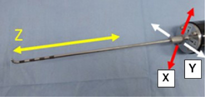
Recently, one author has invented a probing device to measure the resistance of the soft tissues quantitatively in three directions (Fig. 1) [4]. The first direction is for pulling and pushing probe (Z-direction in Fig. 1). The second direction (X-direction in Fig. 1) is vertical to the first direction for hooking or slight holding the soft tissues at the tip of the probe while pulling. The third direction (Y-direction in Fig. 1) is vertical to the above two directions, so that it is the horizontal direction to the probing process. However, at the moment, it has not been clarified whether the probing device can allow us to assess some conditions of the soft tissues. Perhaps, some basic mechanism of hip labrum, which were rarely understood, must be clarified by this probing device. Furthermore, the necessity of the hip capsular closure can be evaluated by this probing device.
Fig. 1.
The probing sensor in the current study. This device can measure force at the tip of the probe in not only the direction of the probe (z), but also two other directions which are perpendicular to the probe-direction.
The purpose of this study was to investigate the resistance of the labrum and the hip capsule quantitatively while they were pulled with the probing device in three surgical steps.
2.Methods
Ten fresh frozen specimens of the pelvis and proximal femur were obtained. Each specimen was mounted with a special device in order to simulate normal hip arthroscopy. the donors included one man and nine women who had a mean age (and standard deviation) of 60 ± 17 years (range, 35 to 88 years) at the time of death. All specimens were screened radiographically to confirm the absence of osseous abnormality.
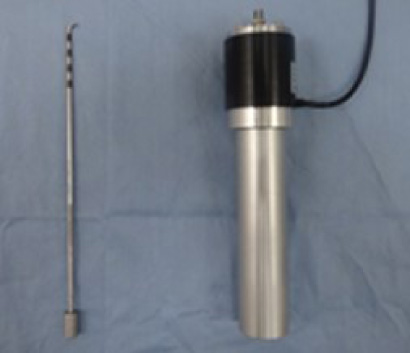
The probing device consisted of the following two components (Fig. 2), one is a probe component; a normal arthroscopic probe of half-length size, and another one is a grip component. A strain gauge was embedded at the top of the grip component, which was behind the connecting part between both two components in order to measure the resultant force of three axis at the tip of the probe. The measurement of the forces was done using the 4-gauge method. In this study, the first force which was along the probe axis (Z-axis in Fig. 1), and one of the two remaining forces (X-axis in Fig. 1) which was along the direction of the hooking or holding of the probe were evaluated. The probing device was connected to the laptop personal computer (PC) via a compact 3ch operation amplifiers (DPA-03A, Tech Gihan Corporation). The measurement range of this device was ±20 N in each direction. Each force of the resistances of the labrum and the capsule while pulling of this probing device with 2.5 mm shifting on the arthroscopy monitor was measured. This shifting device with 2.5 mm was done using the 5-mm interval marked on the probe surface as a reference. The resistance values to the soft tissues were monitored on the PC with a sampling frequency (2 Hz). The maximum value was identified as the resistance values. This measurement was done while the following surgical steps of the labrum and capsule were performed.
Fig. 2.
Two components of the probing device in the current study. The left one is the probe with a half size. Four black marked parts in the tip of the probe to measure a distance of tissues on the monitor. The distance of each part is 5 mm. The right one is the main component to measure the force. 3-axis load cell is embedded in the black measurement part. The grip part is connected with the measurement part.
Each femur of the specimens was dislocated distally with the specific fixation device for simulating of hip arthroscopy. The cannulated needle is then placed just anterior to the greater trochanter. The needle was advanced to the hip capsule. Regarding the access to the joint, the anterior-lateral portal and the modified anterior portal were made [5]. The measurements by the probing device were then started. The tip of the probing device was inserted into the joint through the second portal (the modified anterior portal). The first measurement for the hip capsule was done by pulling the capsule with the probing device through the second portal (left scheme and picture in Fig. 3, closed capsule). After this measurement was done, an inter-portal capsulotomy, which meant a connecting procedure between both two portals, was performed using a radiofrequency ablation device (Super TurboVac 90; ArthroCare, Austin, TX, USA). The second measurement for the hip capsule was done after the following three measurements of the hip labrum (Fig. 4), and the femoral head was relocated into the hip joint (middle scheme and picture in Fig. 3, open capsule). The third measurement of the hip capsule (right scheme and picture in Fig. 3, closured capsule) was done after the joint capsule was sutured twice using the figure of eight technique [6]. The probe was inserted through a tiny gap of the sutured capsule to measure the capsule resistance.
Fig. 3.
Three measurement steps for investigation of capsule resistance while pulling with the probing device. The first step (closed capsule) is shown in the left figures (upper; a scheme, lower; an intracapsular view) and was done with the second portal open. Condition of the capsule is not open despite of the two open portals. The second step (open capsule) is shown in the middle figures (upper; a scheme, lower; an extracapsular view), and was performed while relocating of femoral head into the joint after labral procedures. The third step (closured capsule) is shown in the right figures (upper; a scheme, lower; an extracapsular view) after capsule closure with some capsular closing knots. The tip of the probing device was inserted into the capsule through a gap between the closing knots.
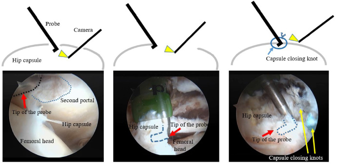
Fig. 4.
Three measurement steps for investigation of labrum resistance while pulling with the probing device. The step in the left figure is the intact phase. The step in the middle figure is after detaching the labrum (line indicates this). The step in the right figure is after labral repair (circle indicates knots for the repair).
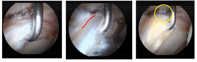
Acetabular labrum resistance was measured at the following three surgical steps after the above inter-portal capsulotomy. There were (1) “Intact” (before the intervention), (2) “After detachment” of the acetabular labrum by 1 cm, and (3) “After repair” with two stiches (Fig. 4). The location of this measurement was at an antero-superior potion, and was kept as much as possible at each step. Regarding the creation of the labral tear, since the anterior-superior rim is the most common location for acetabular tears, the anterior-superior labrum was sharply detached longitudinally from the acetabular rim using a scalpel. This labral tear was completed to full thickness and then repaired.
The measurements of the capsule and the hip labrum were performed three times. The maximum value for each measurement was used as the highest resistance level. For statistical analysis, the highest resistance level in the direction to the axis of the probe (which is identified as z in Fig. 3) and the resultant force which were both of the z direction and the direction (which is identified as x in Fig. 3) of the hook of the probe that is perpendicular to the z direction at each step in the capsule and the labrum was compared using the repeated measured ANOVA.
3.Results
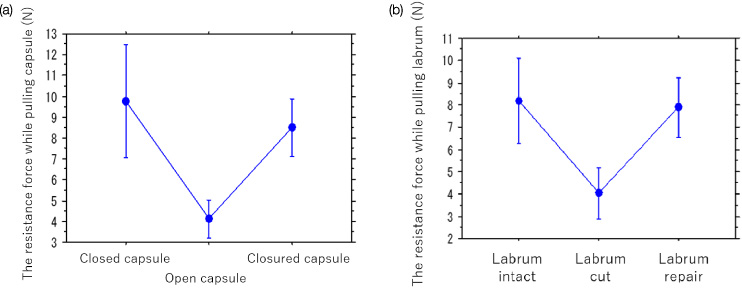
The mean (standard deviation (SD), 95% confidence interval (CI)) highest resistance levels for the capsule in the z direction (i.e. the probe axis) at the three phases were 9.2 N (3.3, 7.0 to 11.4) at the closed capsule, 3.7 N (1.1, 3.0 to 4.3) at the open capsule, and 7.9 N (1.4, 6.9 to 8.8) at the closured capsule. The mean resultant force of the z and x directions of the highest resistance levels at the three phases were 9.8 N (3.5, 7.5 to 12.1) at the closed capsule, 4.1 N (1.2, 3.6 to 4.9) at the open capsule, and 8.5 N (1.8, 7.3 to 9.7) at the closured capsule (Fig. 5(a)). The values at the three phases were statistically significant (p = 0.0004 in the z direction and p = 0.0003 in the resultant force of the z and x directions).
The mean (SD, 95% CI) highest resistance levels for the hip labrum in the z direction at the three phases were 7.2 N (2.5, 5.7 to 8.8) at the labrum intact, 3.0 N (1.4, 2.2 to 3.9) at the labrum cut, and 6.6 N (1.7, 5.6 to 7.7) at the labrum repair. The mean resultant force of the z and x directions of the highest resistance levels at the three phases were 8.2 N (2.7, 6.5 to 9.9) at the labrum intact, 4.0 N (1.6, 3.0 to 5.0) at the labrum cut, and 7.9 N (1.9, 6.7 to 9.1) at the labrum repair. The values at the three phases were also statistically significant (p < 0.0001 in the z direction, and in the resultant force of the z and x directions) (Fig. 5(b)).
Fig. 5.
The resistance force while pulling of capsule (a) and labrum (b) in the three measurement steps.
4.Discussion
We investigated the resistance levels of the labrum and the hip capsule when they were pulled with the probing device that the one author developed [4]. This is the first report about the quantitative evaluation of the resistances of the soft tissues in the hip joint under simulated hip arthroscopy. Since the probing has been normally performed by the surgeons’ feeling, we consider that even simply expressing in figures is meaningful.
One of the most interesting findings in the current paper is that quantitatively measured values might be useful to evaluate whether the lesion of the soft tissue exists. The highest resistance levels of the labrum went down significantly when the labrum was cut from the labrum intact situation (8.2 N to 4.0 N) (Fig 1). The 95% confidence interval of the highest resistance level at the labrum intact (6.5 to 9.9) was not overlapped to that at the labrum cut (3.0 to 5.0). Furthermore, the highest resistance levels of the labrum recovered significantly when the labrum was repaired from the situation of the labrum cut (4.0 N to 7.8 N). Therefore, the measurement by the probing device can evaluate whether a surgical intervention is sufficient. If the highest resistance level is still not enough even when the labrum is repaired, the additional surgical intervention (e.g. one more suture) could be necessary. At the moment, some reports concluded that the labral repair does not affect contact area, distribute load, nor reduce contact stresses in the hip [7–9]. However, we think that it depends on the methods to evaluate the labrum condition. The authors in one of the previous reports tried to evaluate an ultimate load as effect of labral repair with two kinds of suturing methods under simulated full weight-bearing. Although the results of the two suture methods were not significantly different, our probing device can evaluate the difference of several kinds of the labral repair.
The second interesting finding is that the situations of the hip capsule are very similar to the results of the labrum. Recently, the importance of the capsular closure has been popular [2,3]. However, no one has evaluated whether this surgical step is performed sufficiently with a quantitative value. The current study shows that the highest resistance level of the hip capsule went down when the capsule opened, and recovered when the capsule closed. The authors also reckon that this device can be useful to evaluate hip joint instability. In future, a relative large scale study with this probing device might show that threshold of the resistance of the capsule will be determined to evaluate hip joint instability.
One previous report which is similar to the current study showed that theoretical maximum force of three axis to menisci was measured [10]; 3.9 N (SD 2.0 N) while pulling probe. The authors showed that the value was important for training surgical skills. However, since the device in the paper was one bench top type, the measurement in vivo situation (in arthroscopy) was not considered. This previous paper also showed that the probing force cannot be measured in one direction (i.e. the axis of the probe). When the measurement for probe pulling/pushing was done, other direction forces were also detected. In terms of this point of view, we thought that a probing device to measure the forces of the three axis under arthroscopy situation might be necessary.
Authors in other previous papers already developed such a probing device to measure the forces of the three axis under arthroscopy situation [11,12]. A force/torque sensor was fitted onto the base of the handle of a standard knee arthroscopic probe. The sensor was capable of measuring the range of forces that are applied through the instruments (50 N force and 500 mNm torque). The sensor obtained 170 measurements per second of force parameters (Fx, Fy, Fz) and torque parameters (Tx, Ty, Tz). Then, they found some differences between skilled and less skilled surgeons. However, they didn’t show the force values of each axis, and didn’t clarify whether the measurements data was related with conditions of the soft tissue in the joint. We consider that they should have indicated the efficacy of this kind of the probing device in the current study for the evaluation of the soft tissue conditions and the surgical interventions as well as the evaluation of the surgical skill.
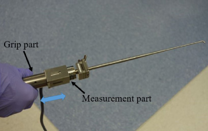
Fig. 6.
Our developed new probing device (probing-sensor, Takumi Precise Metal Work Manufacturing Ltd. Japan). Grip part is sliding (arrow) to the measurement part. It can control a distance of pulling or pushing of the probe.
Tensile property of labrum was done in a previous in vivo study [13]. The authors suggest that labra obtained from male patients have stronger tensile stress than those from female patients, and that degenerative changes may influence the properties of the acetabular labrum. In near future study, we would clarify whether the measurement value with the developed probing device was meaningful to evaluate soft tissue conditions and surgical interventions in clinical studies.
There are several limitations in this study. First, the number of cadavers we used was small, their ages varied, and the gender was not matched perfectly. However, we did select only cadavers without osteoarthritis. Compared with the above factors, this factor must be important. Secondly, we could not control the probing device perfectly. This is because the moving distance of the probing device was controlled on the distance of 2.5 mm using the marker of the probe on the monitor. However, the variance of three times at each measurement was relatively small. Therefore, we think that our method worked well. Currently, we have developed the next prototype, which has a function to control distance while pulling and pushing of probing (Fig. 6)
In conclusion, the probing device to measure quantitatively the resistance of the soft tissues (labrum and capsule) in the hip joint while probing shows that the quantitative resistance levels of the soft tissues are meaningful to evaluate whether a lesion at the soft tissues exists, and some surgical intervention works well.
Acknowledgements
We would like to thank Dr. D.C. Todd for assisting with the experiment.
References
[1] | R. Ganz, J. Parvizi, M. Beck, M. Leunig, H. Nötzli and K.A. Siebenrock, Femoroacetabular impingement: A cause for osteoarthritis of the hip, Clin Orthop Relat Res (417) ((2003) ), 112–120. |
[2] | J.J. Nepple and M.V. Smith, Biomechanics of the hip capsule and capsule management strategies in hip arthroscopy, Sports Med Arthrosc Rev 23: (4) ((2015) ), 164–168. |
[3] | B.G. Domb, M.J. Philippon and B.D. Giordano, Arthroscopic capsulotomy, capsular repair, and capsular plication of the hip: Relation to atraumatic instability, Arthroscopy 29: (1) ((2013) ), 162–173. |
[4] | T. Hananouchi, T. Nishimori, K. Iwakiri, N. Funakoshi, A. Kobayashi and S. Uchida, Resistance of Labrum using a Quantitative Probing Device in Hip Arthroscopy, Orthopaedic Research Society, (2017) , Annual Meeting 2017 March 19–22. |
[5] | S.K. Aoki, J.T. Beckmann and J.D. Wylie, Hip arthroscopy and the anterolateral portal: Avoiding labral penetration and femoral articular injuries, Arthrosc Tech 1: (2) ((2012) ), e155–e160. |
[6] | S.K. Aoki, M.R. Karns, T. Hananouchi and D.C. Todd, Hip arthroscopy capsular closure: The figure of eight Technique, Arthrosc Tech 6: (2) ((2017) ), e505–e509. |
[7] | J.L. Koh and K. Gupta, Evaluation of repair of the hip labrum under simulated full weight-bearing, Hip Int 27: (1) ((2017) ), 104–109. |
[8] | C.R. Henak, B.J. Ellis, M.D. Harris, A.E. Anderson, C.L. Peters and J.A. Weiss, Role of the acetabular labrum in load support across the hip joint, J Biomech 44: (12) ((2011) ), 2201–2206. |
[9] | G.A. Konrath, A.J. Hamel, S.A. Olson, B. Bay and N.A. Sharkey, The role of the acetabular labrum and the transverse acetabular ligament in load transmission in the hip, J Bone Joint Surg Am 80: (12) ((1998) ), 1781–1788. |
[10] | G.J.M. Tuijthof, T. Horeman, M.U. Schafroth, L. Blankevoort and G.M.M.J. Kerkhoffs, Probing forces of menisci: What levels are safe for arthroscopic surgery, Knee Surg Sports Traumatol Arthrosc 19: (2) ((2011) ), 248–254. |
[11] | G. Chami, J.W. Ward, R. Phillips and K.P. Sherman, Haptic feedback can provide an objective assessment of arthroscopic skills, Clin Orthop Relat Res 466: (4) ((2008) ), 963–968. |
[12] | G. Chami, J. Ward, D. Wills, R. Phillips and K. Sherman, Smart tool for force measurements during knee arthroscopy: in vivo human study, Stud Health Technol Inform 119: ((2006) ), 85–89. |
[13] | T. Ishiko, M. Naito and S. Moriyama, Tensile properties of the human acetabular labrum-the first report, J Orthop Res 23: (6) ((2005) ), 1448–1453. |


