
Feasibility research of non-invasive methods for interstitial fluid level measurement
Abstract
This article explores a non-invasive method to determine interstitial fluid level and pressure in tissue. Interdigital electrodes were chosen by simulated results in software “Comsol multiphysis 4.3a”. Environment model similar to human body was created. Measurements were carried out at different situations which can occur during preoperative and afterwards surgery. Non-invasive method decreases possibility of infection and will improve recovery process in postoperative period.
1.Introduction
During preoperative period, the surgery and postoperative period fluid therapy can help to prevent up to 3,000,000 complications after the surgery [1]. By precisely selecting the appropriate amount, type and right timing of intravenous fluids therapy, optimal hydration of tissues can be achieved in order to ensure adequate tissue perfusion, stable hemodynamic and reduce morbidities related to hemodynamic. In everyday clinical practice the amount of fluids to be administered usually is not defined in advance so both liberal (a large quantity of liquid) and restrictive (a small amount of liquid) fluid regimens are used, but exact amount of fluid required to maintain ideal homeostasis is still controversial [2,3]. Amount of fluids required to maintain ideal homeostasis is individual for every patient and depends on patient status, clinical situation, type of the surgery, risk factors, concomitant diseases and conditions [4]. Insufficient amount of fluids used in perioperative period reduces the quality of recovery process postoperatively. An excessive amount of hydration can cause increased morbidity, kidney failure, pulmonary oedema, tissue oedema and decreased tissue oxygenation, which is related to increased risk of surgical wound infection and other complications [5,6].
Interstitial fluid or tissue fluid is a solution that surrounds the tissue cells and supplies them with oxygen and nutrients, while also removes products of metabolism and carbon dioxide. Interstitial fluid is the main component of extracellular fluid and a person has about 10–12 litres of interstitial fluid [6]. In standard conditions pressure of the interstitial fluid can be up to 800 Pa. Excess of the pressure results in development of tissue oedema [7]. In order to choose proper amount of perioperative fluid therapy safe and effective for postoperative patient’s condition it is important and necessary to monitor continuously interstitial fluid volume and its pressure changes. In everyday clinical practice early changes can’t be detected and usually become obvious only later, when clinically significant consequences occur. The literature identifies various invasive and non-invasive methods of interstitial fluid determination, but the most reliable method remains invasive central venous pressure measurement. Other recent invasive (e.g. plasma dilution technique, a wireless implantable interstitial fluid pressure sensor, etc.) or non-invasive methods of interstitial fluid detection (e.g. non-invasive measurement of haemoglobin) have some restrictions and limitations [8]. All new methods would be useful in practise if they would be accurate, reliable, safe and easily replicable [9,10].
Analyses of various published studies’ data showed that it is possible to detect amount of interstitial fluid using interdigital electrodes measuring both changes in electric conductivity and dielectric permittivity [11–14]. Study comparing research subject with a normal level of interstitial fluid and research subject with excess of fluid discovered that it is possible to predict increment or decrement of interstitial fluid amount using non-invasive method, and to perform preliminary pressure calculation [15].
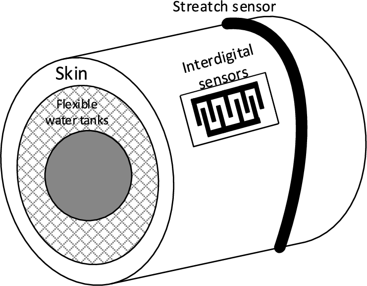
In order to increase the reliability and accuracy of using interdigital electrodes it was suggested to use stretch sensors, which can detect the beginning of tissue oedema [16]. At the beginning of oedema, the tissue fluid build-up in the spaces between cells (also known as tissue spaces) and the tissues start to swell, so stretch sensors detect a change in tension.
The aim of this study was to create model for early detection of interstitial fluid increment using interdigital electrodes and test feasibility of the model in the medium similar to human tissues.
Study protocol was reviewed and agreed by scientific committee at Kaunas University of Technology, Lithuania. All studies were done in accordance with Good laboratory practice.
2.Modelling
To determine increment of the biological tissue fluid in this study interdigital sensor was used.
Electrostatic interdigital electrodes system with n-number of electrodes was described by the equation [17]:
To evaluate capacitance of interdigital capacitor two-dimensional mathematical model was used, which combined iterative positive and negative numbers of electrodes as one pair, which formed one capacitive element [19]
One cell of electrodes consisted of positive and negative pairs of electrodes, capacitance of which was defined as capacitance of three capacitive elements
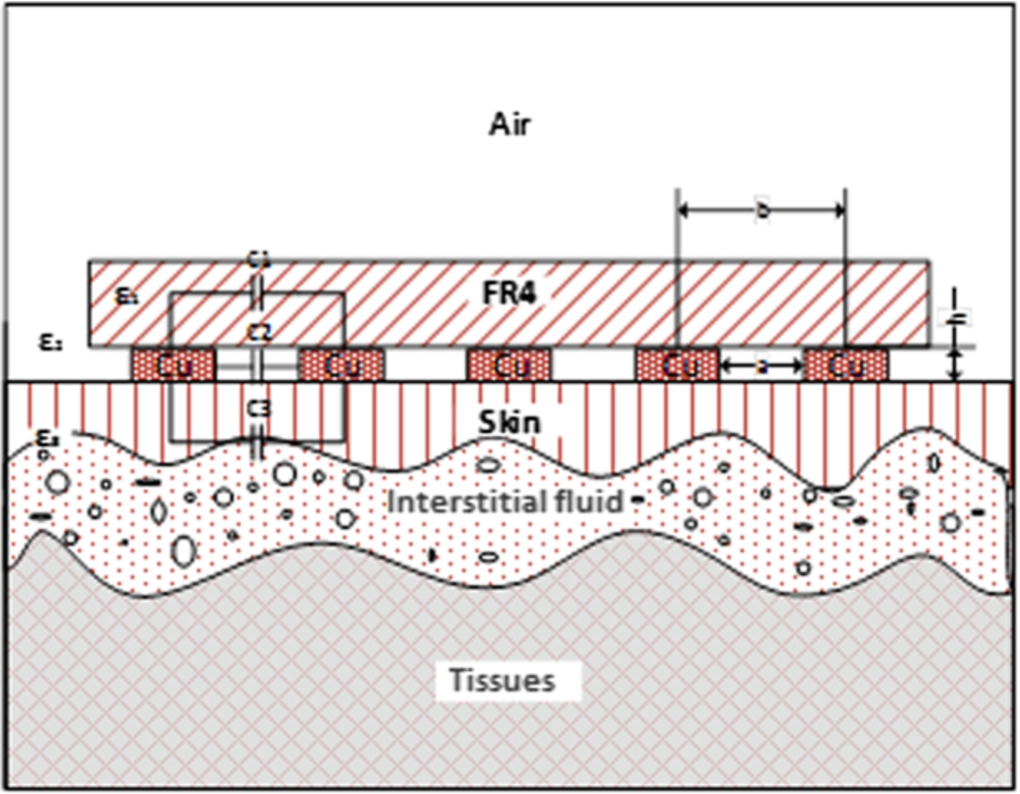
Fig. 1.
Electrical model of human tissues.
For capacitances calculation it was required to know charges and potentials of every electrode, which was not always possible, therefore formula (1) was more suitable for theoretical calculations. In practical tasks to find capacitance between two electrodes we were using alternating voltage, which generated alternating current
In ideal capacitive component phases of harmonic voltages and currents differ: current phase is
With reference to (6) it was possible to define charge Q and electrical capacitance C as:
It was evident, that in all expressions dielectric permittivity was a proportion of capacitance and could be measured by calculating capacitance.
Dielectric permittivity of biological tissues differs in different directions. With regard to formula (9) the biggest energy dependency upon dielectric permittivity was when the direction of electrical field matched with the direction of the component of examined dielectric permittivity.
Modelling showed that electrical field next to the electrode was situated vertically to the surface, but getting further from the surface of the electrode, the direction of the electrical field depended on nearby situated electrodes and dielectric permittivity of the medium.
During simulation of behaviour of the capacitive structures in frequency range impedance was also depending on conductance losses in the structure
Since conductance was not big, loss tangent could be considered equal to conductance:
The real part
Modelling goal was to find the most optimal arrangement of the electrodes enabling to measure the biggest difference in impedance and capacitance, which depend on increase of the interstitial fluid.
To model the process “COMSOL Multiphysics 4.3a” software based on finite element analysis was used. Using this software interdigital sensor and medium with characteristics close to human tissue were modelled. A model with assigned electrical parameters, namely conductivity and electric permittivity, was developed (Fig. 1, Table 1) [21–23]. Electrical parameters of air, copper, tissues and FR4 were not changed during simulation process and were accepted as constants.
In order to determine optimal quantity, length and step of electrodes simulation of electrical field of capacitive element was performed. Electrical impedance dependency on the frequency in the system was computed, where biological tissues were used as dielectric in capacitive element.
Task was solved in three-dimensional (3D) space. In this case geometry was described in a more complex way and took more time, but this allowed analysing of simulation data in a more convenient way.
After defining model geometry boundary conditions were assigned to separate parts: copper was assigned to the meander shape capacitive element, 3 V were assigned to one electrode and 0 V to another. Above electrodes thin FR4 plate was placed. Also, between electrodes and skin thin insulating polyethylene film layer and dielectrics for skin and tissue fluids imitation were placed. Imperative boundary conditions were implemented by space with air, which surrounds the whole structure.
Table 1
Electrical parameters of materials used in modelling
| Item | Electrical Parameters | |
| ε | σ [S/m] | |
| Air | 1 | 0 |
| Copper | 1 | 6.00E+07 |
| Substrate (FR4) | 4.5 | 0.004 |
| Skin | 33–44 | 0.0002–0.00002 |
| Interstitial fluid | 59–73 | 0.41–0.8 |
| Tissue | 16 | 0.03 |
After primary simulation stage it was claimed that it is possible to measure absolute impedance value and changes in capacitance while changing the amount of tissue fluid in subcutaneous tissue. Also optimal parameters of the electrodes was determined (
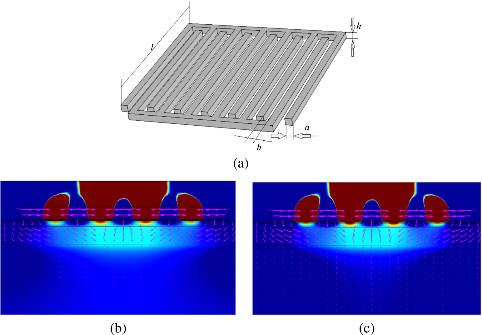
Fig. 2.
Distribution of electric potential, when conductance of skin is 0.00011 S/m, dielectric permittivity – 38.5: (a) electrodes geometry; (b) at 10 kHz frequency; (c) at 100 kHz frequency.
3.Experimental model
We created experimental model to test the results of simulation. Schema of the structure of experimental model is provided in Fig. 3.
Fig. 3.
Structure of experimental model.
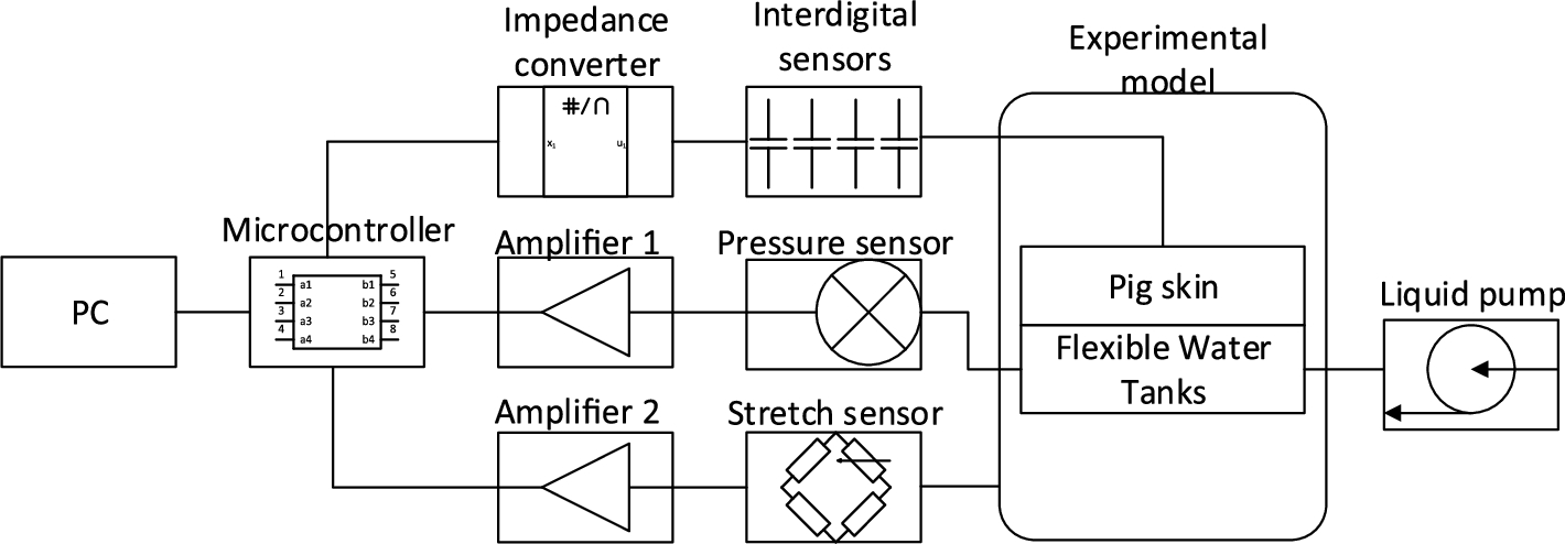
To conduct experiment we used water reservoir, internal part of which was made from rigid material and external part was made from elastic latex rubber. To create conditions as close as possible to the alive organism tissues we put 3 mm thick porcine skin above the water tank. Round shape of water reservoir was selected to match limb of alive subjects. Input and output tubes were mounted on the opposite sides of reservoir to ensure equal distribution of water in the system. Pressure measuring sensor “SM5470” was connected next to the output tube to determine water pressure [24]. We made three interdigital sensors with 0.5 mm, 2 mm and 2.5 mm step electrodes (Fig. 4). To reduce external factors’ influence on the measurement results, electrodes were covered with foam for the shielding purposes. “Analog Devices” AD5933 chip capable of measuring impedance from 1 kΩ to 10 MΩ with 0.5% error was used for impedance and capacitance measurements. To decrease noise influence shielded cable was used (Fig. 4). Stretch sensor was used to measure tissue swelling amount [16] (Fig. 5).
Fig. 4.
Experimental equipment: (a) Interdigital sensor (b) “Analog Devices” AD5933 evaluation board.
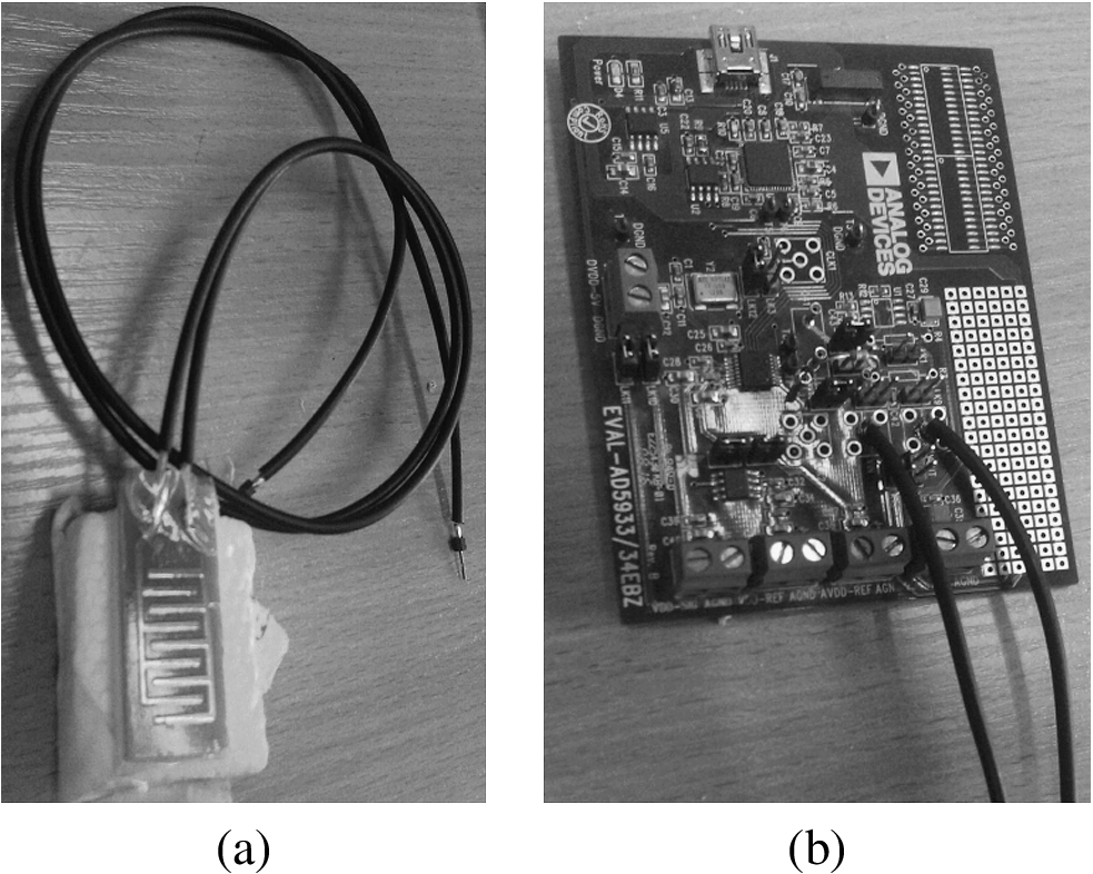
Fig. 5.
Experimental model with stretch sensor.
4.Experiment results
We performed measurements of impedance and capacitance with three types of interdigital sensors put on empty system and system filled with water using frequency in range from 10 kHz to 100 kHz.
Fig. 6.
Impedance difference between empty system and system filled with water. Measurement was made with tree types of electrodes.
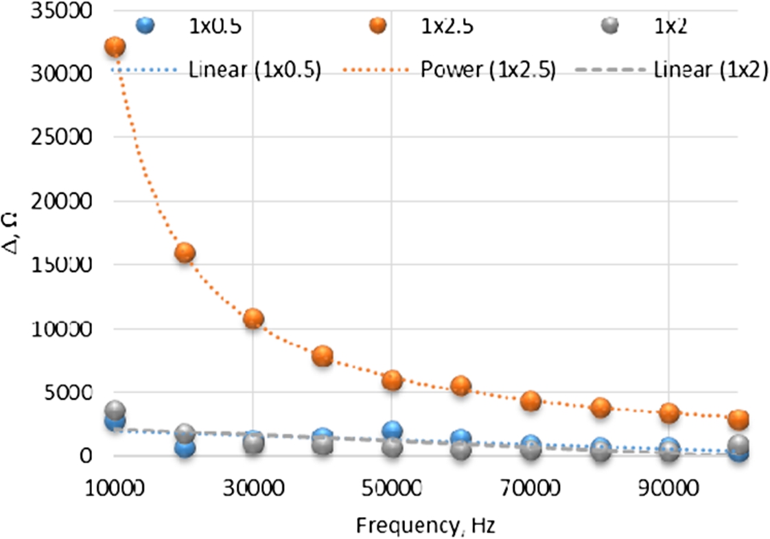
The biggest difference in impedance between empty and filled system was equal to 32 kΩ and was registered at low frequency. At high frequency difference in impedance was 3 kΩ. The biggest difference in impedance was registered using electrodes with 2.5 mm step (Fig. 6).
Fig. 7.
Capacitance difference between empty system and filled with water. Measurement was made with tree types of electrodes.
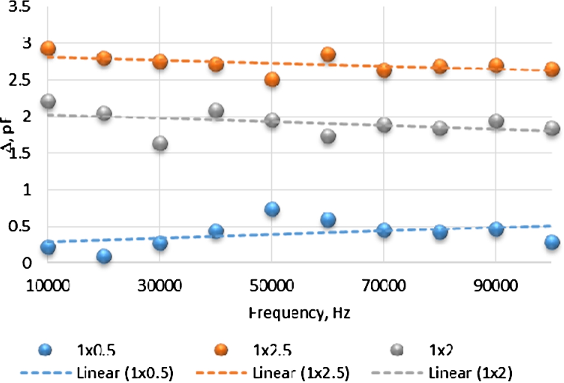
The biggest difference in capacitance, while changing the amount of fluid in the system, was captured with 2.5 mm step electrodes. With the change in amount of fluid difference of 3 pF in capacitance was captured (Fig. 7).
Further measurements were performed from 11 kHz to 20 kHz with 2.5 mm step electrodes, because the biggest difference in impedance and capacitance was obtained in this range.
To imitate increase of interstitial fluid in subject water was gradually injected into a system. Total 3 injections of 7 ml of water were done with one minute break between injections. Measurements were performed without any interruptions. Measured frequency range 11 kHz (Fig. 8).
Fig. 8.
Impedance change dependency of the amount of water in the system. Measurements completed at 11 kHz frequency.
Increase of water in the system resulted in decrease of impedance. Between filled and partially filled system impedance differed by 5.8 kΩ. System response to the 7 ml water increase was equal to decrease in impedance by 3.86 kΩ.
Because measurements were made at 11–20 kHz frequency range capacitance was measured at every deduction
Fig. 9.
Capacitance change dependency of the amount of water in the system at frequency range 11–20 kHz.
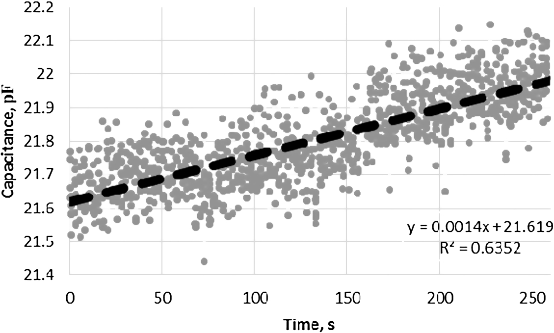
Total 1691 values of capacitance were registered. From the perceived results, capacitance changed from 21.6 pF to 21.9 pF. System response to 7 ml increase of amount of water was equal to increase in capacitance by 0.1 pF (Fig. 9).
Conducted experiment confirmed assumption that increase in amount of water in hypodermic layer results in decrease of impedance and increase of capacitance. More precise measurements are received at low frequencies, because at low frequencies electric field proceeds not through the cells, but outruns them, so impedance depends only on amount of tissue fluid in the spaces between cells (Fig. 10). At high frequencies impedance of tissues is measured instead of impedance of fluid surrounding the cells.
![Absolute impedance value dependency of frequency [25].](https://content.iospress.com:443/media/bme/2017/28-6/bme-28-6-bme1699/bme-28-bme1699-g010.jpg)
It is not enough to determine only amount of interstitial fluid during surgery and after it. It is important to know what pressure is generated in tissue layer.
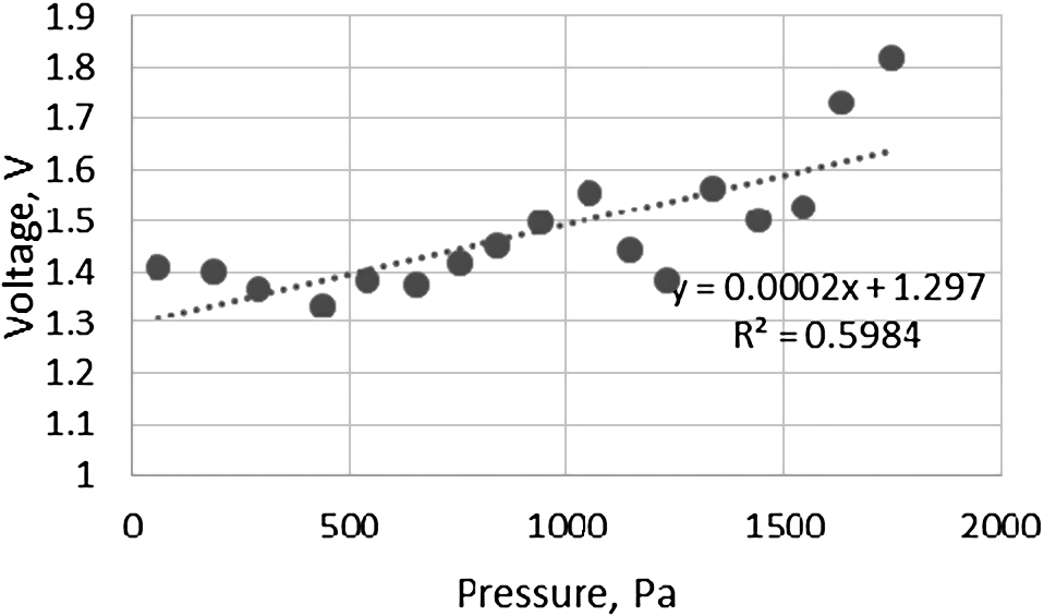
During experiment pressure generated by water and tissue expansion (swelling) was measured. At every corresponding value of pressure voltage of stretch sensor and impedance was measured.
Regression analysis showed that the proportion of the stretch sensor voltage variance predictable from the pressure is not big (
Fig. 11.
Stretch sensor voltage dependency of water pressure in the system.
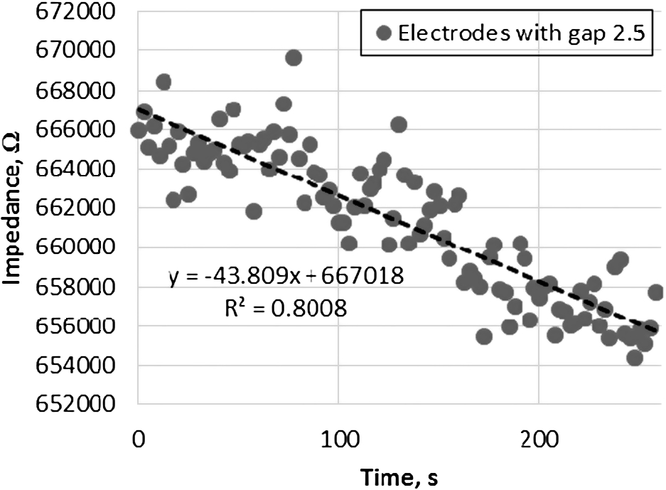
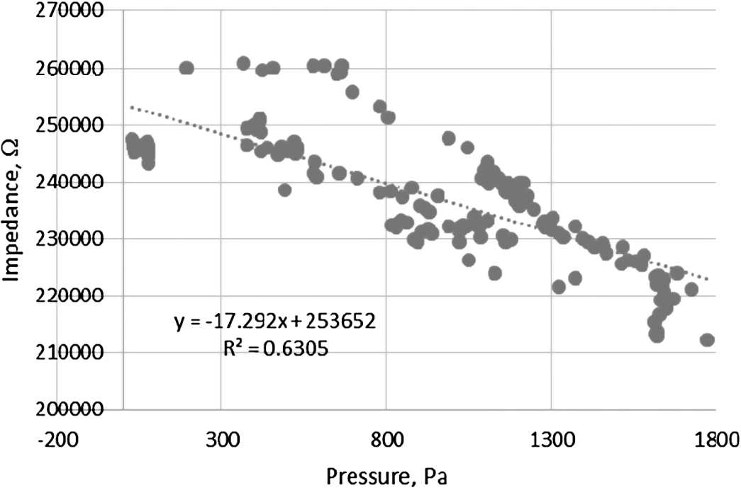
The regression analysis showed moderate impedance and pressure relationship (
Fig. 12.
Impedance dependency of water pressure in the system.
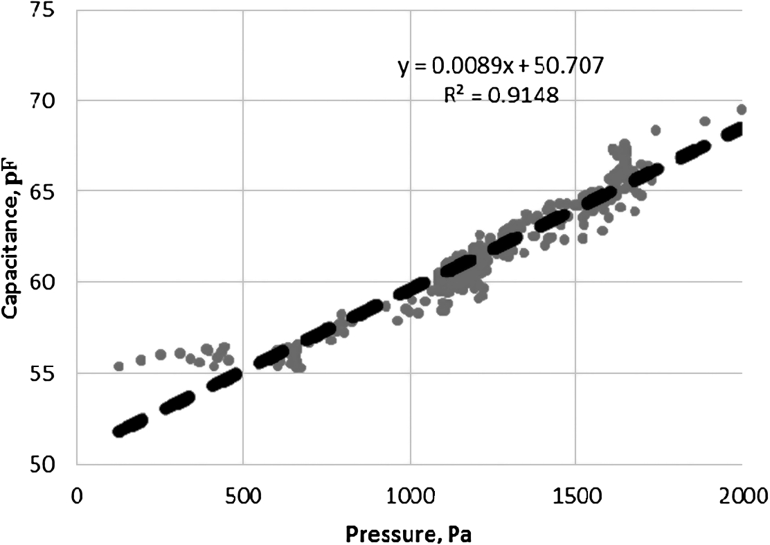
The regression analysis showed that pressure and capacitance had strong relationship (
Fig. 13.
Capacitance dependency of water pressure in the system.
5.Conclusions
Our modelling and experiment confirmed assumption that measuring of skin impedance and capacitance are suitable to detect interstitial fluid increase in hypodermic layer with regard to amount and pressure of interstitial fluid. Interdigital electrodes with 2.5 mm step demonstrate the highest resolution. More precise measurements are received at low frequencies. To identify amount of interstitial fluid and increase in pressure more reliably it is recommended to use stretch sensor. Further high-quality experimental studies and clinical trials with alive research subjects using different types of intravenous fluid are needed to confirm method efficiency and reliability and validate use in clinical practice.
Conflict of interest
The authors have no conflict of interest to report.
References
[1] | M.A. Hamilton, M. Cecconi and A. Rhodes, A systematic review and meta-analysis on the use of preemptive hemodynamic intervention to improve postoperative outcomes in moderate and high-risk surgical patients, Anesthesia & Analgesia 112: (6) ((2011) ), 1392–1402. doi:10.1213/ANE.0b013e3181eeaae5. |
[2] | A. Andrijauskas, C.H. Svensen, J. Ivaskevicius, N. Porvaneckas, G. Kvederas and U. Marmaite, Goal directed fluid therapy revised: Indirect monitoring of interstitial fluid accumulation during mini fluid challenges with Crystalloids, The Open Conference Proceedings Journal 3: (1) ((2012) ), 42–51. doi:10.2174/2210289201203010042. |
[3] | A. Andrijauskas, I. Sakaviciūtė, J. Ivaskevicius, N. Porvaneckas, G. Kvederas, D. Cincikas et al., Perioperacinė skysčiu ˛ terapija: Senos problemos, nauji sprendimai, Lietuvos chirurgija 10: (1) ((2012) ). Available from: http://www.zurnalai.vu.lt/lietuvos-chirurgija/article/view/1980/1211. |
[4] | V. Markevicius, A. Andrijauskas, D. Navikas, N. Dubauskiene, N. Porvaneckas, E. Stankevicius et al., In silico testing of the semi-closed loop infusion system with a new simulator, Elektronika ir Elektrotechnika 20: (9) ((2014) ). doi:10.5755/j01.eee.20.9.8520. |
[5] | M. Cannesson, G. Pestel, C. Ricks, A. Hoeft and A. Perel, Hemodynamic monitoring and management in patients undergoing high risk surgery: A survey among North American and European anesthesiologists, BioMed Central 15: (4) ((2011) ). Available from: http://www.ncbi.nlm.nih.gov/pmc/articles/PMC3387639/pdf/cc10364.pdf. |
[6] | D. Chappell, M. Jacob, K. Hofmann-Kiefer, P. Conzen and M. Rehm, A Rational Approach to Perioperative Fluid Management. Anesthesiology. Ovid Technologies, Vol. 109: , Wolters Kluwer Health, (2008) , pp. 723–740. |
[7] | R. Gutmann, M. Leunig, J. Feyh, A. Goetz, K. Messmer, E. Kastenbauer et al., Interstitial hypertension in head and neck tumors in patients: Correlation with tumor size, Cancer research 52: (7) ((1992) ), 1993–1995. Available from: http://www.ncbi.nlm.nih.gov/pubmed/1551128. |
[8] | S. Song, A. Kim, M. Brown, C. Jung, S. Ko and B. Ziaie, An implantable wireless interstitial pressure sensor with integrated Guyton chamber, IEEE Transactions on Biomedical Engineering. Institute of Electrical & Electronics Engineers (IEEE) (2016), 1–1. |
[9] | C. Morris and D. Rogerson, What is the optimal type of fluid to be used for peri-operative fluid optimisation directed by oesophageal Doppler monitoring?, Anaesthesia 66: (9) ((2011) ), 819–827. doi:10.1111/j.1365-2044.2011.06775.x. |
[10] | C. Challand, R. Struthers, J.R. Sneyd, P.D. Erasmus, N. Mellor, K.B. Hosie et al., Randomized controlled trial of intraoperative goal-directed fluid therapy in aerobically fit and unfit patients having major colorectal surgery, in: British Journal of Anaesthesia., Vol. 108: , Oxford University Press, (2012) , pp. 53–62. Available from: http://bja.oxfordjournals.org/content/108/1/53.long. |
[11] | B.N. Nordbotten, Bioimpedance measurements using the integrated circuit AD5933, 2008. Available from: https://www.duo.uio.no/bitstream/handle/10852/11202/Nordbotten.pdf?sequence=1. |
[12] | S.-J. Guild, F.D. McBryde and S.C. Malpas, Recording of intracranial pressure in conscious rats via telemetry. Innovative methodology [Internet], Journal of Applied Physiology 119: (5) ((2015) ), 576–581. Available from: http://jap.physiology.org/content/119/5/576.full.pdf. |
[13] | L. Nilsson, Samba Preclin Samba 200 product presentation [Internet], 2011. Available from: https://www.harvardapparatus.co.uk/hapdfs/Samba_Presentation_UK.pdf. |
[14] | S.H. Song, M. Brown, T. Maleki and B. Ziaie, A Wireless Interstitial Pressure Sensor with a Guyton Chamber, IEEE, (2013) , pp. 2161–2164. doi:10.1109/Transducers.2013.6627230. |
[15] | L. Koziol, J.J. Pitre Jr., J.L. Bull, R.E. Dodde, G. Kruger, A. Vollmer et al., The feasibility of using compression bioimpedance measurements to quantify peripheral edema, Journal of Electrical Bioimpedance 5: (1) ((2014) ). doi:10.5617/jeb.929. |
[16] | Stretch sensors product information. Available from: https://www.adafruit.com/product/519. |
[17] | V. Markevicius, D. Navikas, A. Valinevicius, D. Andriukaitis and M. Cepenas, The soil moisture content determination using interdigital sensor, Elektronika ir Elektrotechnika 18: (10) ((2012) ), 25–28. doi:10.5755/j01.eee.18.10.3055. |
[18] | S. Soloman, Sensors Handbook, McGraw-Hill Professional, New York, (2009) , p. 1385. |
[19] | J. Persad, S. Rocke, A. Abdool and D. Ringis, Skin variations impact on non-invasive measurement of blood glucose with Interdigital electrodes, 2015. Available from: https://www.comsol.com/paper/download/258671/persad_paper.pdf. |
[20] | K.G. Ong and C.A. Grimes, A resonant printed-circuit sensor for remote query monitoring of environmental parameters, Smart Materials and Structures 9: (4) ((2000) ), 421–428. |
[21] | G. Elert, Dielectrics – the Physics Hypertextbook [Internet], (1998) . Available from: http://physics.info/dielectrics/. |
[22] | S.M. Klein, L. Prantl, S. Geis, M. Eisenmann-Klein, J. Dolderer, O. Felthaus et al., Pressure Monitoring During Lipofilling Procedures. Clinical Hemorheology and Microcirculation, Vol. 58: , IOS Press, (2014) , pp. 17–19. doi:10.3233/CH-141872. |
[23] | D. Andriukaitis and R. Anilionis, Investigation of etching process in nano structures, Elektronika ir Elektrotechnika 86: (6) ((2008) ), 77–80. Available from: http://www.eejournal.ktu.lt/index.php/elt/article/view/11189/5925. |
[24] | Pressure sensor “SM5470” product information [Internet], 2016 Available from: http://www.si-micro.com/en/products/view/72. |
[25] | Impedance dependence from frequency [Internet], 2016. Available from: http://ucan2weightloss.com.au/wish-you-knew-how-to-lose-weight-feel-great-for-this-summer/cells/. |

