
Design of ultra-long-distance optical transport networks based on high-order remotely pumped amplifier
Abstract
In order to further increase the span length of the Optical Transport Network (OTN) transmission system, a combination of Raman amplifier and remotely optical pumped amplifier (ROPA) configuration scheme is recommended. Optimal EDF length, optimal ROPA position and OTN span limitation are obtained through simulations. A field-trial with 8*10 Gb/s in 380 km span system is carried out with the amplifier configuration of Raman amplifier plus first-order and second-order remotely pumped amplifier. By adding a second-order remote pump laser, the transmission limit is increased from 77.5 dB to 80.7 dB. Through detailed analysis of the system, it is concluded that the second-order remote pump can effectively transfer the pump power to the first-order remote pump wavelength, which greatly increases the pump power at the gain module, thereby increasing the gain of the RGU and reduce its noise. Moreover, the introduction of the second-order remote pump effectively weakened the self-excited effect and overcomes the shortcomings of the low pump power threshold of the first-order remote pump.
1.Introduction
There is an increasing request in ultra-long unrepeatered transmission submarine systems due to the tremendous growth of global data traffic, especially for subsea networks in recent years. Unrepeatered transmission systems are cost-effective solutions when the accesses to intermediate points are difficult.
Typical applications are submarine links connecting islands to the mainland or island hopping, and the communication links to offshore oil and gas platforms [3–5,9,16,17]. There are also other cases in terrestrial networks such as in desert, mountain, and forest areas. In an ultra-long span system, amplifiers and pumping lasers are placed at the transmitter and receiver terminals to allow data transmission without in-line active elements in the fiber links. It is quite challenging to increase the transmission span length, since the optical power is launched only from the terminals. Among the possibilities to extend the span length, the use of passive ROPA has already been studied with dedicated fiber for remote pumping [3,17], in-line Raman noise filtering [3,17], or ultra large effective area fiber [3,5]. Some of these amplification schemes may obtain the good performance, but would be challenging for a practical implementation.
Distributed Raman amplification (DRA) and ROPA are very beneficial technologies to enlarge the transmission distance in long-haul WDM transmission systems thanks to their excellent low noise characteristics [2,6–8,10–15]. Especially, an optimized combination of a DRA and a ROPA, was recently proposed to demonstrate an enhancement of optical signal to noise ratio (OSNR) and a long-distance terrestrial field-trial [7,8].
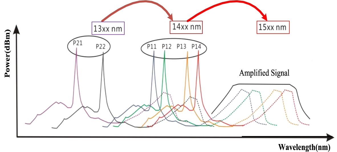
DRA is an effect of energy transfer from short-wavelength pump to long-wavelength signal in the optical transmission. High-order distributed Raman amplification technology or high-order remotely pumped amplification technology,which achieved by multistage Stokes transfer between pumps of different wavelengths is applied, as shown in Fig. 1. In high-order ROPA technology, Remote pumped module (RPU) contains six pump wavelengths distributed in the range between 1300 nm and 1500 nm, the two wavelengths of second-order pump source (P21, P22) operate in the range between 1300 and 1400 nm, the four wavelengths of first-order pump source operate in the range between 1400 and 1500 nm (P11, P12, P13, P14).
Fig. 1.
Pump power transfer schematic diagram of high order DRA or ROPA.
One of the limiting factors for ROPA is very low residual pump power available into the Er-doped fiber (EDF). For example, in a backward ROPA, both the pump and signal power begin at high power levels at the transmitter and receiver terminals respectively. Furthermore, both pump and signals traveling through the long span fiber, resulting in very low pump (<10 mW) and very low signal powers (<−30 dBm per channel) into the EDF of the ROPA. Another limiting factor is strong ASE noise in the transmission fiber due to DRB (double Rayleigh backscattering) when the pump power is strong, eventually causing lasing. In order to improve the efficiency of a backward ROPA, the EDF used for the backward ROPA must provide high small signal gain with high gain efficiency and a low NF using as little pump power as possible. In this paper, we simulate and get the optimal EDF length, optimal RGU position and OTN span limitation. Also a field trial with 8*10 Gb/s signals in 380 km span system is evolved. The fiber amplifier configuration of DRA plus first-order and second-order ROPA are compared in the field test.
2.Simulation results
2.1.Theory
According to the theory of nonlinear optical fiber transmission, we starts from the Maxwell equations, the vector wave equation is derived and the slow-varying envelope approximation is introduced. During the process, the third-order dispersion, the third-order nonlinear self-phase and cross-phase modulation effects are considered, the optical pulse transmission equation in WDM transmission system is [8]:
In the equation, Ai is the intensity amplitude of the channel i, α is loss coefficient, β2 is group velocity dispersion parameter, β3 is third order dispersion parameter,the sum of β2 and β3 denotes fiber dispersion. γi is nonlinear coefficient of channel i. The first and second terms on the right side of the equation correspond to self-phase and cross-phase modulation effects, respectively.
Considering the third-order dispersion and the complete third-order nonlinear effect of the fiber, we can get [1]:
γ is the nonlinear coefficient, the second item in the right parenthesis is the time-varying item and the self-steepness of the pulse edge which is related to the formation of the shock. This item also includes the nonlinear energy loss caused by Raman scattering in the pulse.
In Eq. (2.2), the self-phase modulation delay response term is called in-band Raman scattering. Since the Raman effect has a weaker effect on self-phase modulation, this item can be ignored. The stimulated Brillouin scattering effect is weak, so it is also ignored in (2.2). Considering (2.1) and (2.2), we can get following optical transmission equation of ultra-long span optical fiber:
In Eq. (2.3), the left side of the equation is the second-order dispersion term, the third-order dispersion term and the loss term. The terms on the right side of the equation are self-phase modulation instantaneous response, cross-phase modulation instantaneous response, cross-phase modulation delay response, and Raman amplification terms. Table 1 shows the simulation parameters.
Table 1
Simulation parameters
| Parameters | Value | Units |
| Signal wavelength | 192.1∼193.0 | THz |
| Booster amp power | 27 | dBm |
| Pre amp Gain | 30 | dB |
| CORA pump power | 1050 (Max) | mW |
| Raman wavelength | 1425, 1457 | nm |
| Second order pump (RPU) | 1360 | nm |
| First order pump (RPU) | 1478 | nm |
| Fiber length | 380 | km |
| Fiber loss(1550.12 nm) | 0.2 | dB/km |
| Dispersion coefficient | 17 | ps/nm/km |
| Fiber nonlinear coefficient | 2.6e−20 | m2/W |
| Fiber Aeff | 80 | um2 |
2.2.Simulation results
2.2.1.Power distribution
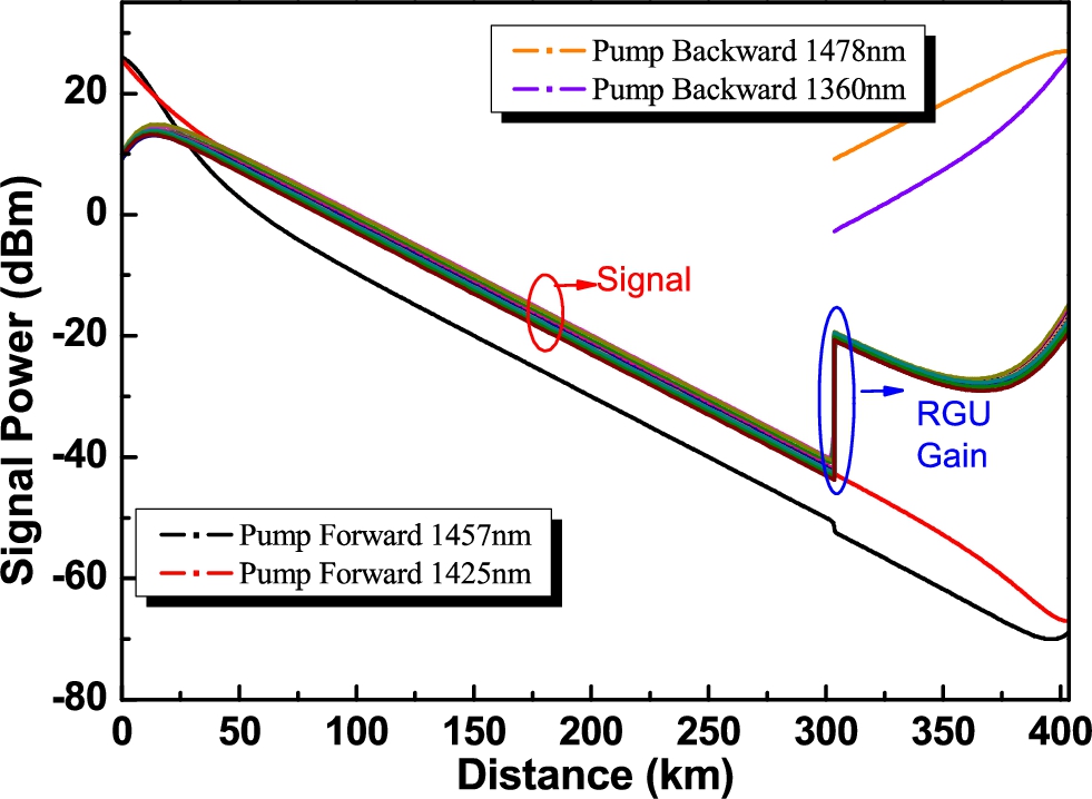
Figure 2 shows the pump and signal power distributions along fiber distance. The remotely pump power is launched from the receiver terminal. 1478 nm is the first-order wavelength of remotely pump. 1360 nm could be served as second-order Raman pump. The pump power is transfer from 1360 nm to 1478 nm. Here the pump power of 1425 and 1457 nm are the wavelength of the forward first-order Raman amplifier. Ten channels with 100 GHz space interval and Raman pump power are launched in the transmitter terminal. The signal with power of 10 dBm/ch is amplified by the commercial forward Raman amplifier and reaches its max power at 25.6 km location. After that the power decreased along the fiber until they enter RGU. RGU is the passive part of ROPA, which is located in the place 100 km away from the RPU, active part of ROPA. At RGU, the signals are amplified by the RPU pump.
Fig. 2.
Power distribution of signals and pumps along fiber.
2.2.2.Optimal erbium fiber length
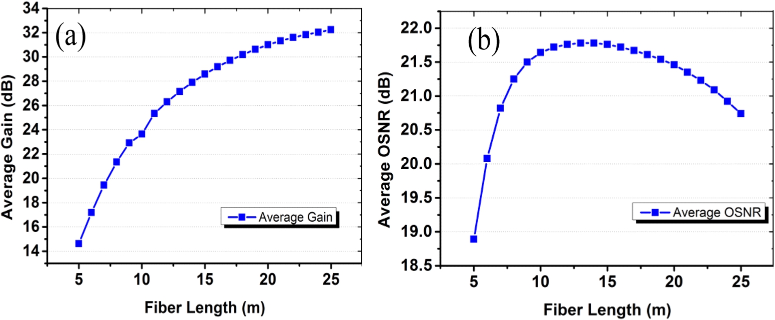
Figure 3 shows the effect of the length of the erbium-doped fiber on the performance of the ROPA. The simulation results show that when the erbium-doped fiber is too short, the gain of the remote pump amplifier is small, resulting in poor OSNR of the received signal. When the length of the erbium-doped fiber is less than 13 m, the gain of the remote pump amplifier increases rapidly as the length of the erbium-doped fiber increases, and the signal OSNR becomes better. When the length of the erbium-doped fiber is longer than 13 m, the amplifier gain begins to approach the extreme value. At the same time, the longer erbium-doped fiber also increases the ASE noise, so the received signal OSNR begins to decrease. OSNR is relatively high when EDF length is between 13 m to 15 m.
Fig. 3.
The average gain and OSNR vs. EDF length.
2.2.3.Optimal RGU location
RGU position (fiber distance from transmitter or receiver terminal) is the basic parameter of ROPA, which determines the performance of amplifier and transmission networks. The simulation explores the impact of the RGU location in the remote pump amplifier on the performance of the transmission system. Here, the EDF length is 13 m. We got following relationship between average gain (average OSNR) and RGU distance from receiver terminal as shown in Fig. 4.
Fig. 4.
Average gain and average OSNR vs. RGU distance from receiver terminal.
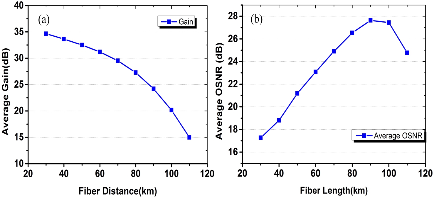
Figure 4 shows the detailed effect RGU location on the performance of the remote pump amplifier. The simulation results show that when the RGU is close to the receiver terminal, the pump power is high, which makes the gain of the remote pump amplifier extremely high. However, due to the long transmission distance of the signal, it caused poor OSNR in the receiver side. The OSNR is best when the RGU is placed 90 km away from receiver terminal. In the practical implementation, a balance between gain and OSNR is needed to be considered.
2.2.4.Span limit distance
Figure 5 shows the change of the signal Q2 value with the transmission distance. The Q2 value of the transmission signal has an approximately linear relationship with the increase in the transmission distance. When the transmission distance is less than 380 km, the signal in the receiving module is approximately error-free. Figure 5 shows that the remote pump amplifier supports up to 380 km error-free transmission.
Fig. 5.
Q2 value vs. transmission fiber length.
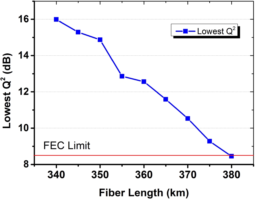
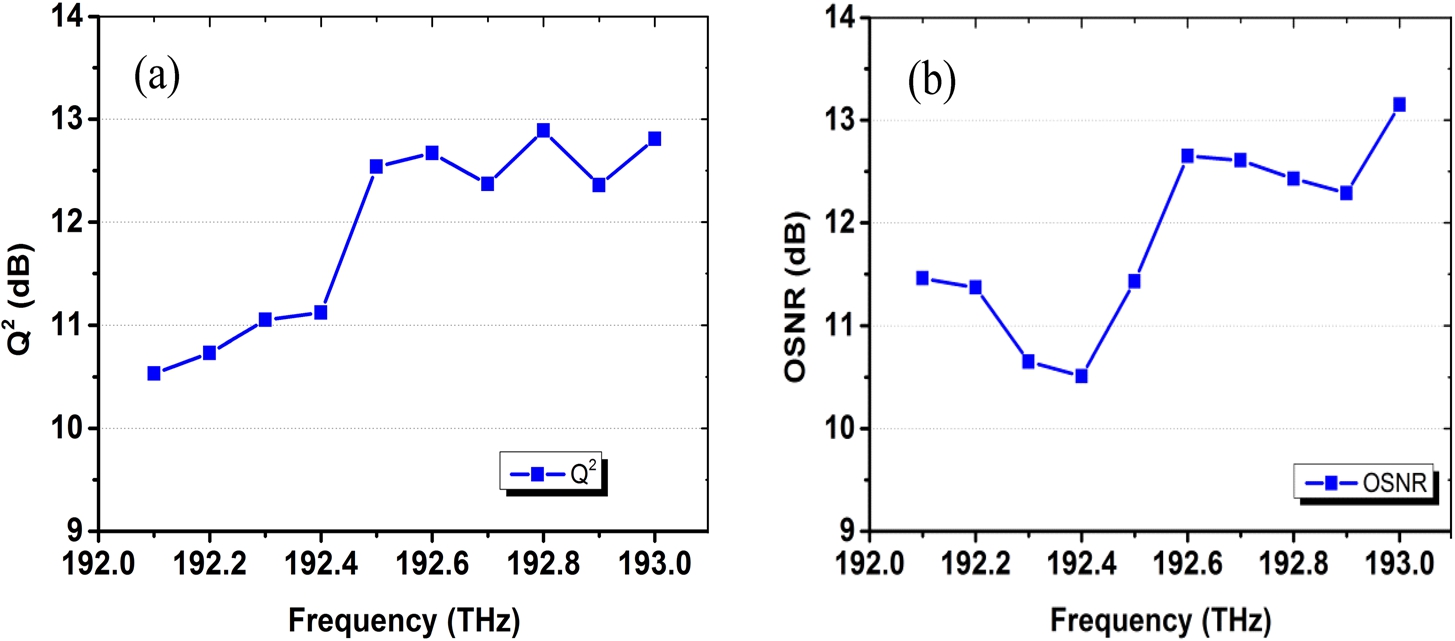
Figure 6 shows the Q2 value and OSNR of the 10 channels in the receiving module. The simulation results show that the Q2 values of all channel signals are higher than the FEC threshold of 8.5 dB. The channel with a longer received signal wavelength has a better Q2 value, which is consistent with the received signal optical power and OSNR distribution.
Fig. 6.
Q2 value and OSNR of ten signals at receiver terminal.
3.Experimental results
Fig. 7.
Schematic diagram of the experimental setup.
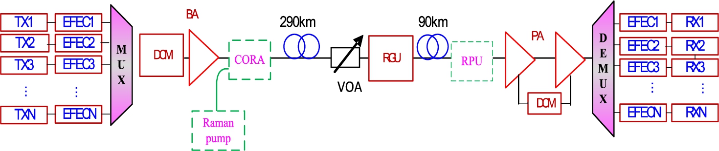
Figure 7 shows the configuration of the OTN system. The transmission equipment is an industrial product consisting of eight line Terminal transponders whose wavelengths are irregularly spaced from 1547.71 to 1560.68 nm (modules that can be found in the laboratory). Each transmitter consists of a SDH 9.95 Gb/s module followed by an enhanced Forward Error Correcting encoder and then a WDM module using NRZ format at 10.71 Gb/s. The eight transmitters are combined before entering a booster amplifier, followed by a co-propagating Raman amplifier. The max power of the BA is 24 dBm.
The 380 km transmission fiber is composed by two spans, one span is 290 km and another span is 90 km. The total loss of the link at 1550.12 nm is 72.2 dB (including connector loss) representing a mean loss of 0.19 dB/km. With a mean chromatic dispersion of 17 ps/nm/km at 1550.12 nm, most of the 6460 ps/nm line chromatic dispersion is compensated in the receive terminal by Dispersion Compensating Fiber modules (DCM). The loss of the DCF modules is compensated by a pre amplifier (PA) in which there is a filter to filter the high ASE power. Finally the signals are demultiplexed and detected by the individual line Terminal receivers. The transmission is evaluated by measuring the OSNR by optical spectrum analyzer (OSA) and by optical network tester (ONT-506).
According to the optimal RGU position by simulation, the RGU is placed 90-km away from the receiver terminal. The RGU module is consist of a 13 m long EDF and pumped by first-order pump laser centered at 1478 nm or pumped by the combination of first-order pump and second-order pump laser centered at 1478 nm and 1360 nm. The total power of 1st pump is 720 mW and the total power of second-order pump is 1.5 W.
Fig. 8.
The control method of second-order pump laser by commercial Raman amplifier.
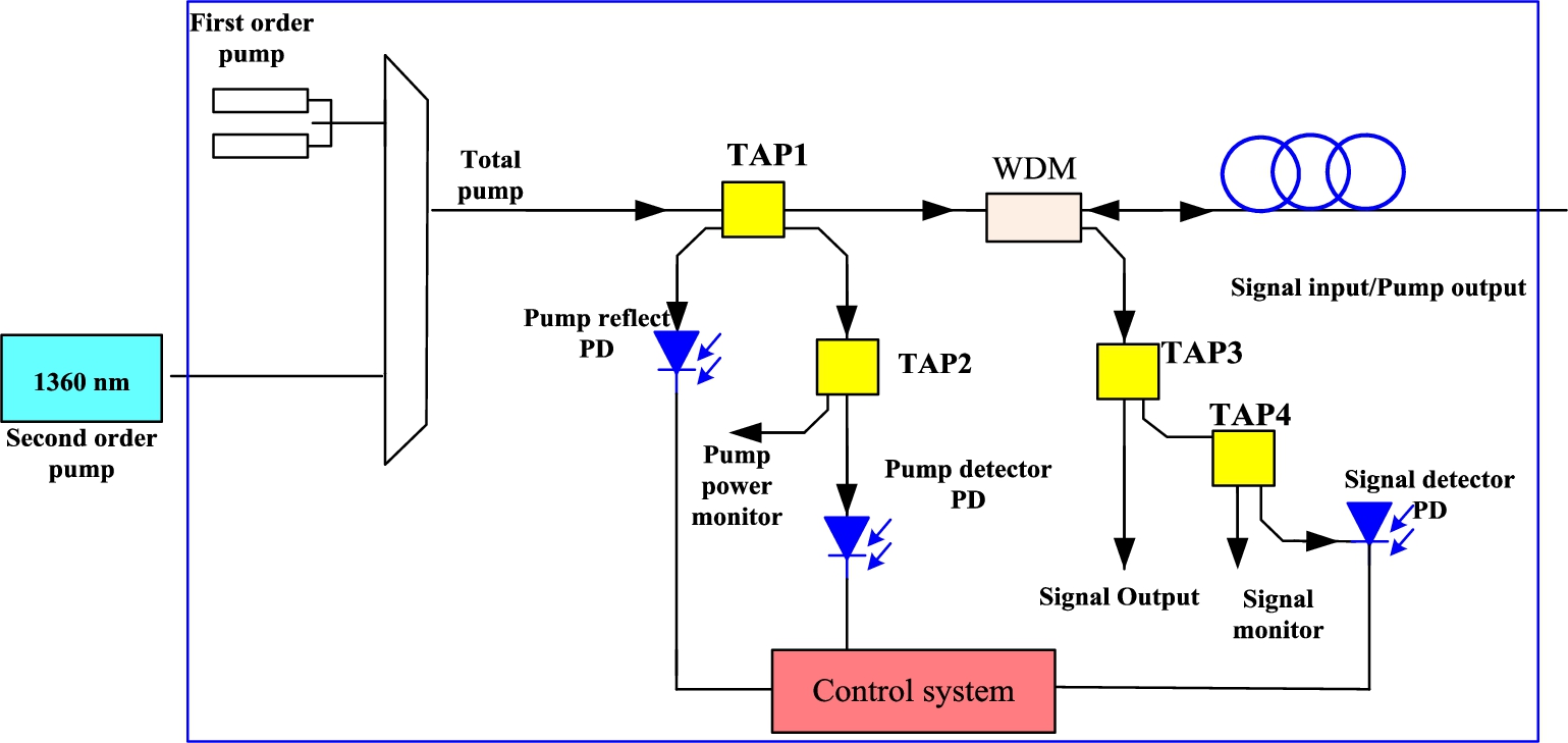
The control method of second-order pump laser by commercial Raman amplifier is shown in Fig. 8. The blue line shows the existing first-order Raman control chart. Two first pump lasers are combined to form first-order Raman pump Unit. The control system (control CPU) controls the switching of the pump lasers, pump power warning, reflecting power warning, signal power warning through pump detector PD, pump reflect PD and signal detector PD. The second-order laser is launched through an extra port of the commercial first-order Raman amplifier. The two first-order laser at 1478 nm and second-order laser at 1360 nm are combined by pump multiplexer. The second-order pump is also controlled through the control system of the first-order Raman amplifier. They share the control CPU and alarm PDs including pump alarm, pump reflection alarm and signal alarm which make the circuit control very simple. At the same time, the cost is also significantly reduced.
Fig. 9.
OSNR and signal spectrum of 1st and 2nd ROPA.
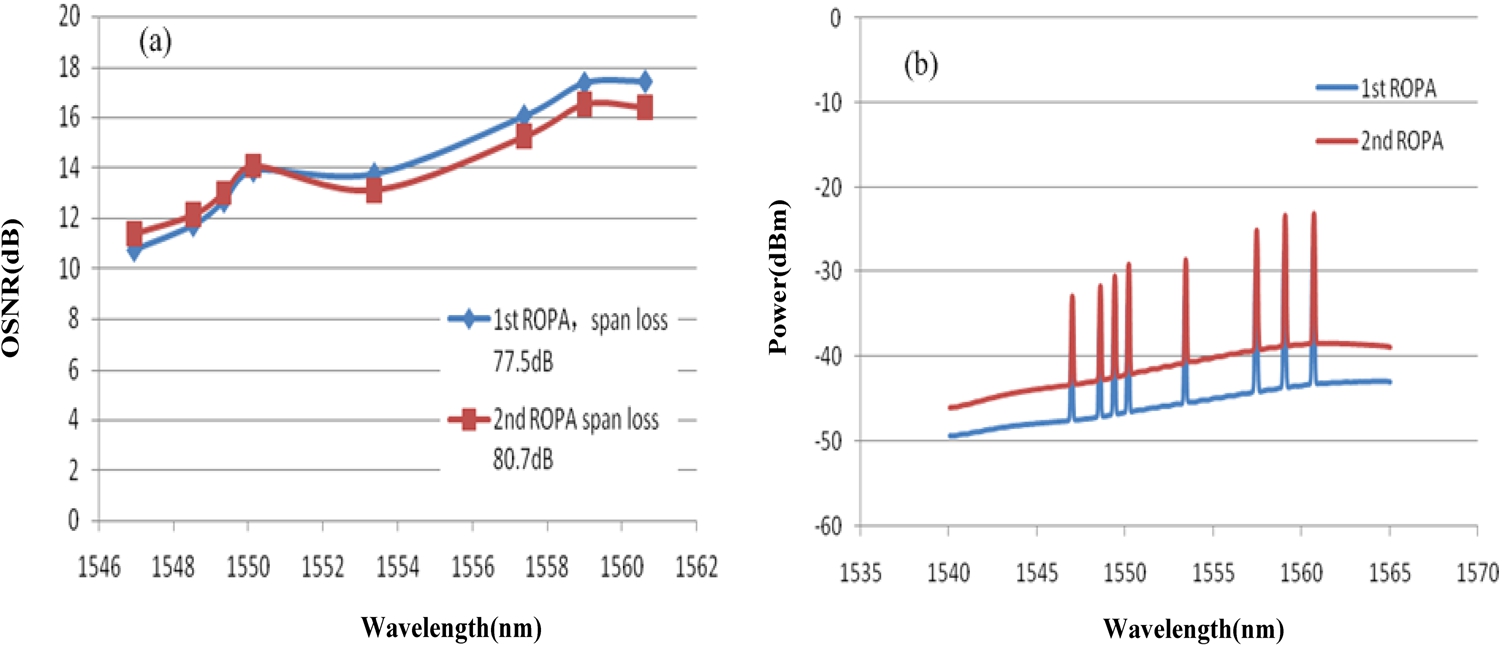
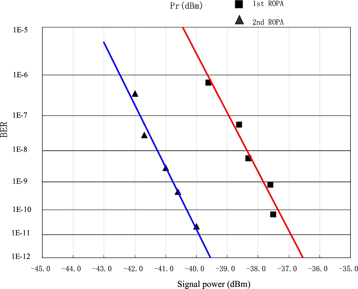
Measured OSNR and signal spectrum for first-order (1st) ROPA and second-order (2nd) ROPA are shown in Fig. 9. The blue diamond dot denotes OSNR of 1st ROPA. After 380 km transmission fiber, the total power budget is 77.5 dB, the ONSR of 8 channels is from 10.73 dB to 17.44 dB. As shown in the Fig. 9a, the OSNR is positively tilted which caused by Raman cross-talk between the channels. At the end of the 380 km line, the different channels have the average OSNR of 14.19 dB/0.1 nm. The red square dot is OSNR of second-order ROPA. In this case, we get 80.7 dB power budgets. And the average OSNR is nearly 14 dB. Figure 9b shows the spectra before the PA. Figure 10 shows the BER against received light level. We can see that receiver sensitivity is improved from −36.6 dBm to −39.6 dBm. Almost 3 dB receiver sensitivity is obtained when we add an second order pump to the 1st ROPA.
Fig. 10.
BER curve of first-order and second-order ROPA.
4.Conclusions
In this paper, we simulated the amplifier configurations with distributed Raman amplifier and first-order and second-order ROPA. From the simulation results, we got optimal EDF length of ROPA, optimal RGU lotation and transmission span length limitation. We also demonstrated 8*10 Gb/s DWDM channels transmission over 380-km unrepeated link with G.652 fiber. The good performance of unrepeated transmission was achieved by using forward Raman amplifier plus ROPA. The amplification scheme of forward Raman amplifier plus second-order ROPA is the recommended way to extend span length, which can effectively increase the transmission margin of the system.
Through experiment, we compare a 380-km unrepeated system with first-order ROPA and second-order ROPA. We can get 77.5 dB loss budget for first-order ROPA and 80.7 dB loss budget for second-order ROPA. And 3.2 dB link budget is obtained by use of second-order remote pump.
Acknowledgements
The authors would like to thank Wuxi Taclink Optoelectronics Technology Co., Ltd. (TACLINK) and Wuxi Hannuo Optoelectronic Technology Co., Ltd. for their useful equipment used in the experiments. This work was supported by the 333 project of Jiangsu province (RA2019148), Six talent peaks project in Jiangsu Province (XYDXX- 169) and Future Network Scientific Research Fund Project(SN:FNSRFP-2021-YB-56)
Conflict of interest
None to report.
References
[1] | G.P. Agrawal, Nonlinear Fiber Optics, Academic Press, (2005) . |
[2] | M.H. Ali, S. Majid et al., Pump power optimization for hybrid fiber amplifier utilizing second order stimulated Raman scattering, Optical and Quantum Electronics 52: (6) ((2020) ), 274. doi:10.1007/s11082-020-02400-x. |
[3] | H. Bissessur et al., Unrepeatered transmission of 29.2 Tb/s over 295 km with probabilistically shaped 64 QAM, in: Proc. Eur. Conf. Opt. Commun., (2018) , Paper Th1G4. |
[4] | H. Bissessur, P. Bousselet, D. Mongardien, G. Boissy and J. Lestrade, 4 × 100 Gb/s nrepeatered transmission over 462 km using coherent PDM-QPSK format and real-time processing, in: Proc. 37th Eur. Conf. Exhib. Opt. Commun, (2011) , Paper Tu. 3.B.3. |
[5] | D. Chang et al., Unrepeatered 100 G transmission over 520.6 km of G.652 fiber and 556.7 km of G.654 fiber with commercial Raman DWDM system and enhanced ROPA, IEEE J. Lightw. Technol. 33: (3) ((2015) ), 631–638. doi:10.1109/JLT.2014.2356498. |
[6] | Y. Chen, J. Song, J. Ye et al., Power scaling of Raman fiber amplifier based on the optimization of temporal and spectral characteristics, Optics Express 28: (8) ((2020) ). |
[7] | R. Chi, Experimental optimization of the scheme of second-order Raman amplifiers based on ultra-long spansystems, Results in Physics 18: ((2020) ), 103195. doi:10.1016/j.rinp.2020.103195. |
[8] | R. Chi, T. Lu and X. Sun, Theoretical and experimental study on ultra-long unrepeated optical fiber link based on bidirectional Raman amplifier, Modern Physics Letters B ((2020) ). |
[9] | S. Etienne, H. Bissessur, C. Bastide and D. Mongardien, Ultra-long 610 km unrepeatered transmission of 100 Gb/s using single fiber configuration, in: Proc. Eur. Conf. Opt. Commun, (2015) , Paper Th2.2.5. |
[10] | A. Iqbal et al., Noise performance improvement of broadband discrete Raman amplifiers using dual stage distributed pumping architecture, Journal of Lightwave Technology 37: ((2019) ). |
[11] | L. Krzczanowicz, W. Forysiak, P. Harper et al., High-capacity multi-span transmission performance characterization of broadband discrete Raman amplifier, Optics Express 28: (12) ((2020) ). |
[12] | S. Liang, S. Jain, L. Xu et al., High gain, low noise, spectral-gain-controlled, broadband lumped fiber Raman amplifier, Journal of Lightwave Technology 99: ((2020) ), 1. doi:10.1109/JLT.2020.3012285. |
[13] | U.C.D. Moura, F.D. Ros, A.M.R. Brusin et al., Experimental characterization of Raman amplifier optimization through inverse system design, Journal of Lightwave Technology 99: ((2020) ), 1. |
[14] | Tehranchi et al., Gratings with longitudinal variations in coupling coefficients: Super-efficiency and unidirectionality in distributed feedback Raman fiber lasers, New Journal of Physics 22: ((2020) ), 103022. doi:10.1088/1367-2630/abbc2a. |
[15] | Y. Xie, Q. Feng, W. Li, Q. Zheng and Y. Wang, A channel model to deal with distributed noises and nonlinear effects in a fiber system with distributed Raman amplifiers, Applied Sciences 10: (1) ((2020) ), 133. |
[16] | B. Zhu et al., 6.3-Tb/s unrepeatered transmission over 402-km fiber using high power Yb-free clad-pumped L-band EDFA, in: Proc. Opt. Fiber Commun. Conf, (2014) , Paper W1A.2. |
[17] | B. Zhu et al., 800 Gb/s (8 × 128 Gb/s) unrepeatered transmission over 515-km large-area ultra-low-loss fiber using 2nd-order Raman pumping, Opt. Express 24: (22) ((2016) ), Art. no. 25291. doi:10.1364/OE.442351. |

