
Action of torsion and axial moment in a new nonlinear cantilever-type vibration energy harvester
Abstract
The effects of composite motion involving action of torsion and axial moment on the vibrating element on characteristics of a new cantilever-type nonlinear electromagnetic vibration energy harvester are analyzed. The systems with softening and hardening action of the magnetic force are analyzed. The impact of the phenomenon on electromagnetic quantities of the system is investigated using the 2d analytical and 3d numerical models. The simulated and measured frequency-response characteristics show noticeable differences when the phenomenon is taken into account.
1.Introduction
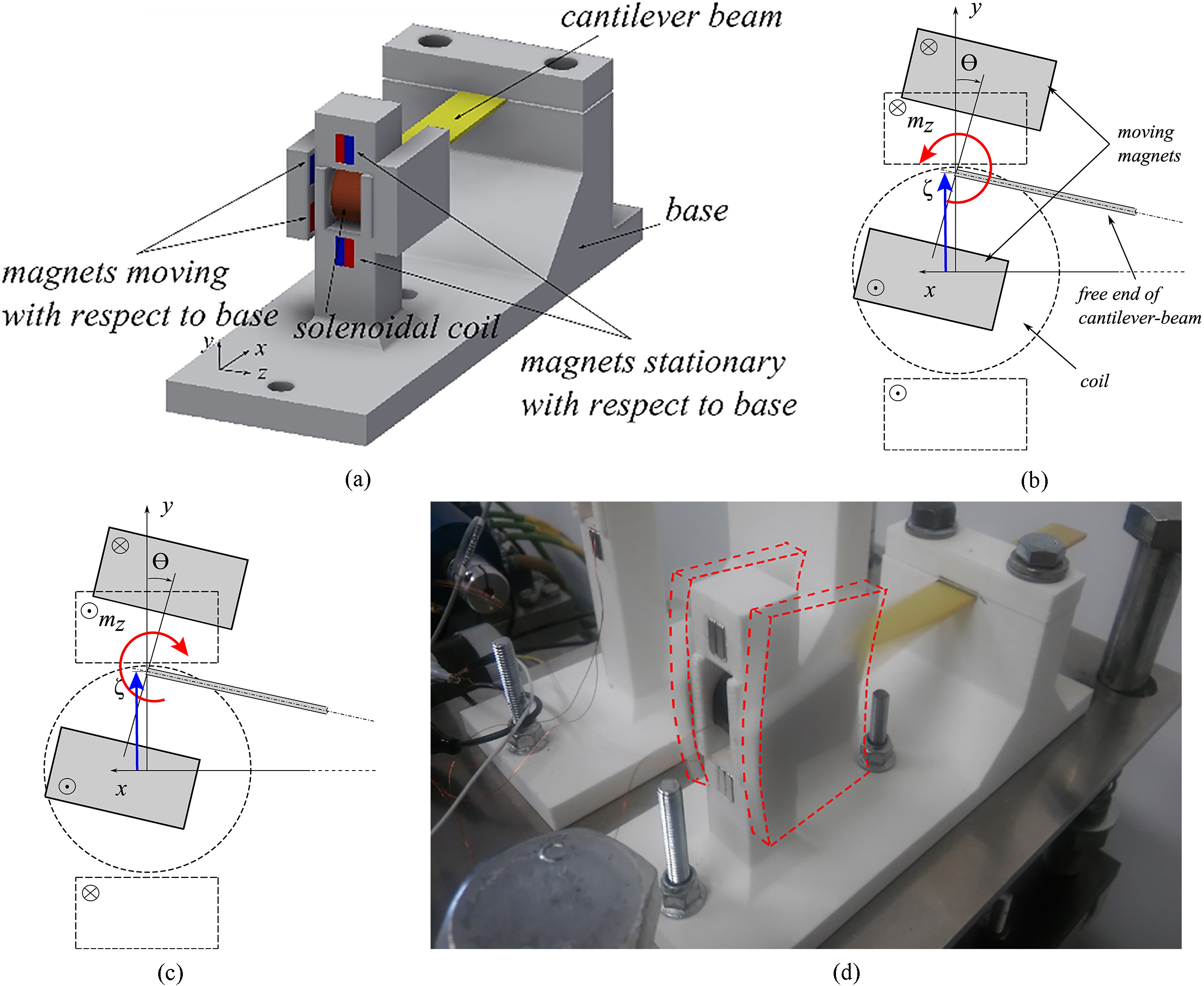
The nonlinear vibration energy harvesters attract attention due to potential to widen the frequency bandwidth at varying conditions [1, 2, 3, 4]. In the electromagnetic harvesters the nonlinearity is brought by action of magnets on a core [3] or on other magnets [5, 6]. To overcome some limitations of these configurations a microgenerator with a coreless magnetic circuit, depicted in Fig. 1a, was proposed by authors [6]. Generally, in this type of harvesters it is sufficient to represent the kinematics by one degree of freedom [1, 2, 3, 5]. This is not the case for the system considered here, in which the angle
The considered system is capable to switch the magnetic stiffness between hardening (Fig. 1b) and softening (Fig. 1c) action by reversing the magnetization sense of the stationary magnets. The two separate structures are distinguished in this way for which, depending on the magnetization sense, the axial magnetic moment attempts to straighten or to buckle the beam. Clearly, if
Figure 1.
Harvesters considered: a) CAD drawing of entire configuration, b)–c) illustration of complex motion for system with hardening and softening action of the magnetic force, respectively; circled markers denote the magnetization vector senses going forth (
2.Mathematical models and results
2.1Electromagnetic quantities
The harvesters in Fig. 1b and c are considered as the two structures, which will be referred to as HS (hardening, stable around
(1)
on the
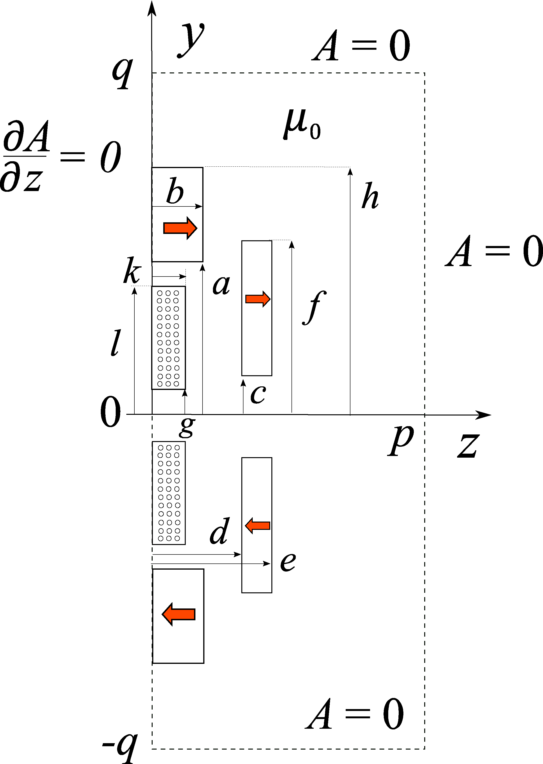
Figure 2.
Model for calculations of magnetic field distribution; arrows indicate magnetisation senses (SU harvester).
The expressions derived from solution of Eq. (1) that describe the magnetic force and the flux linkage are, respectively
(2)
(3)
where
(4)
(5)
(6)
(7)
(8)
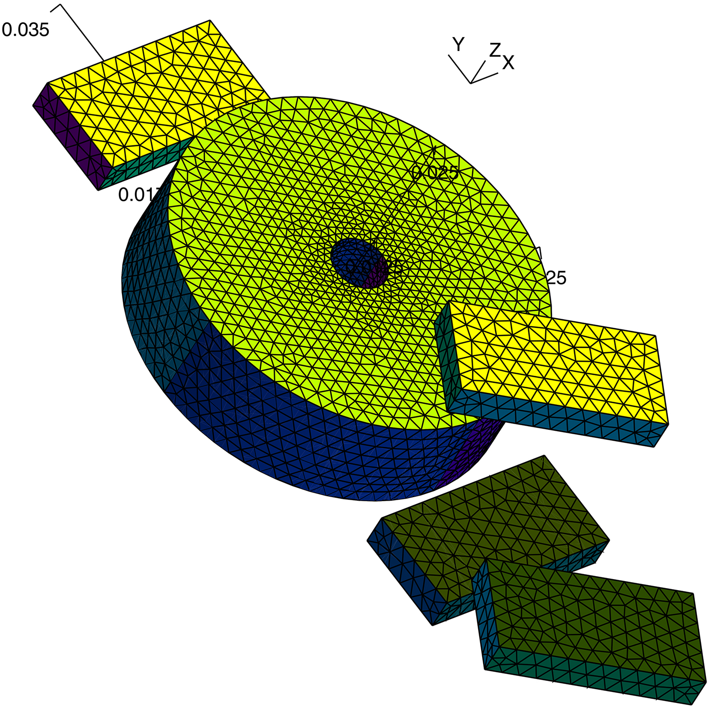
Impact of complex motion on the electromagnetic quantities of was taken into account using a 3d finite element model for magnetic field calculations [8]. The specifications of modeled systems are given in Table 1.
Table 1
Specifications of parameters common for HS and SU harvesters used in calculations of electromagnetic quantities
| Parameter | Value |
|---|---|
| a, b, c, d, e, f, g, h, k, l | 16.5, 3, 8.5, 10.4,13.4, 12, 0.5, 25.5, 4, 14 mm |
| p, q | 70 mm, 70 mm |
|
| 18 mm |
|
| |
|
| 1000 turns |
Figure 3.
Finite element model showing a 3d mesh for one half of the system considering composite motion.
In computations the motion was approximated assuming that the barycenter of “grey magnets” moves along a circle with radius equal to the beam length, as they rotate around the barycenter about the angle
The variations presented in Fig. 4 are for the SU system. For the HS system the variations in Fig. 4b and c are multiplied by
2.2Frequency-response characteristics
Assessment of the impact of complex motion on the frequency response characteristics was carried out via solution of equations derived from the Timoshenko beam theory [7], considering the electromagnetic coupling
(9)
(10)
and the electric circuit
(11)
where
Table 2
Specifications of parameters common for HS and SU harvesters for calculations of frequency characteristics
| Parameter | Value |
|---|---|
| Cantilever beam material | Glass fiber/epoxy composite |
|
| 2730 kg/m |
|
| 7250 GPa, 2971 GPa |
|
| 0.0036 N |
|
| 23 |
|
| 0.024 kg |
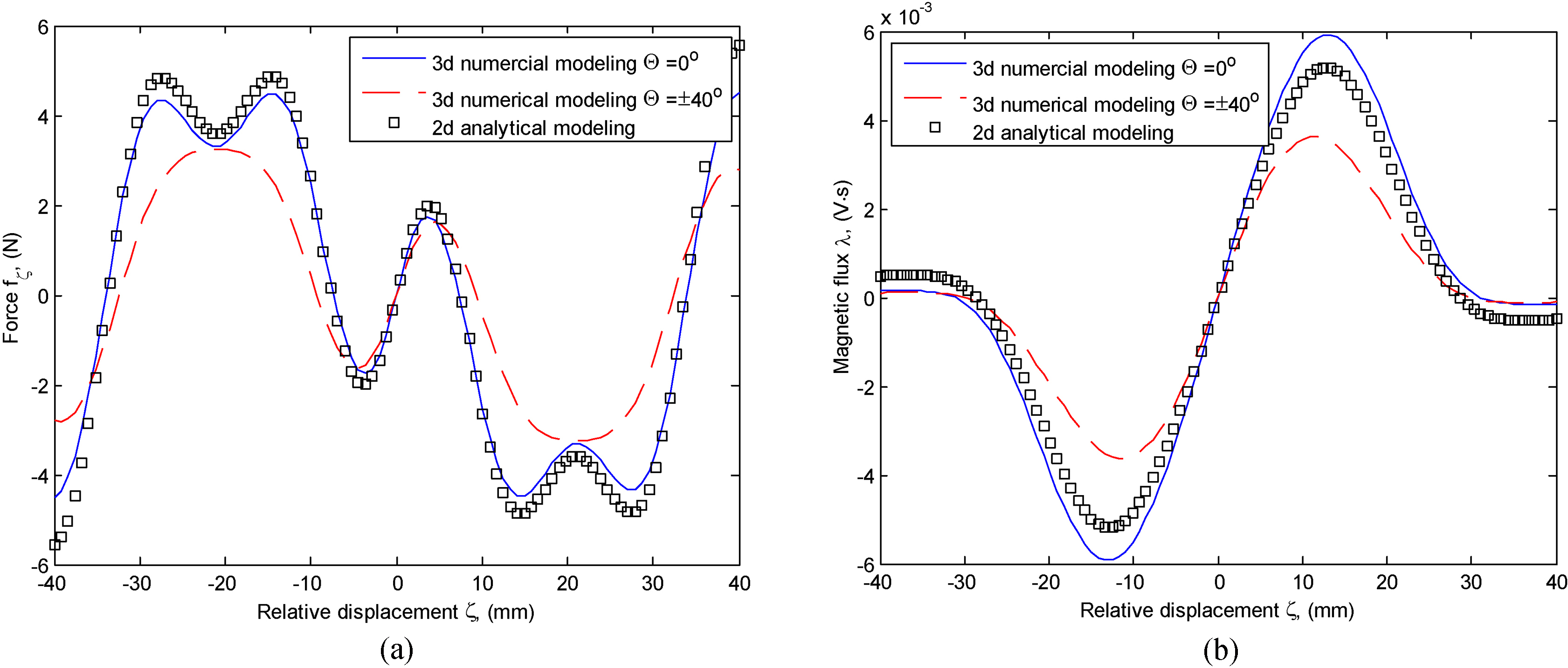
Figure 4.
Results of 3d finite element modeling (SU harvester): a) magnetic force
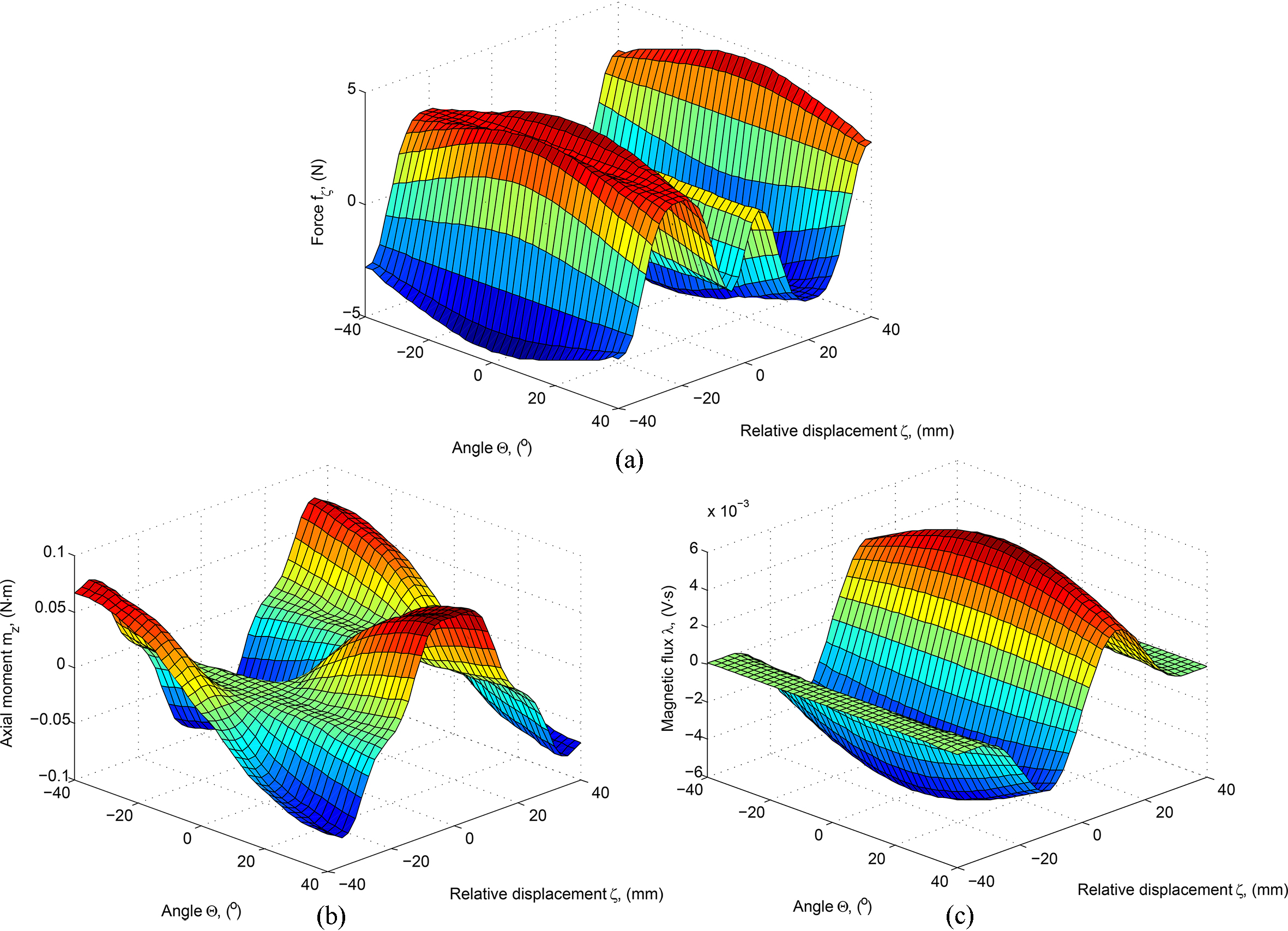
Figure 5.
Comparison of electromagnetic quantities calculated using different models (SU harvester).
The characteristics were determined via time-domain solution of Eqs (9)–(11) using a chirp signal with a constant magnitude and a linear frequency sweep for
Figure 6.
Diagram of laboratory test test-stand for measurement of frequency characteristics.
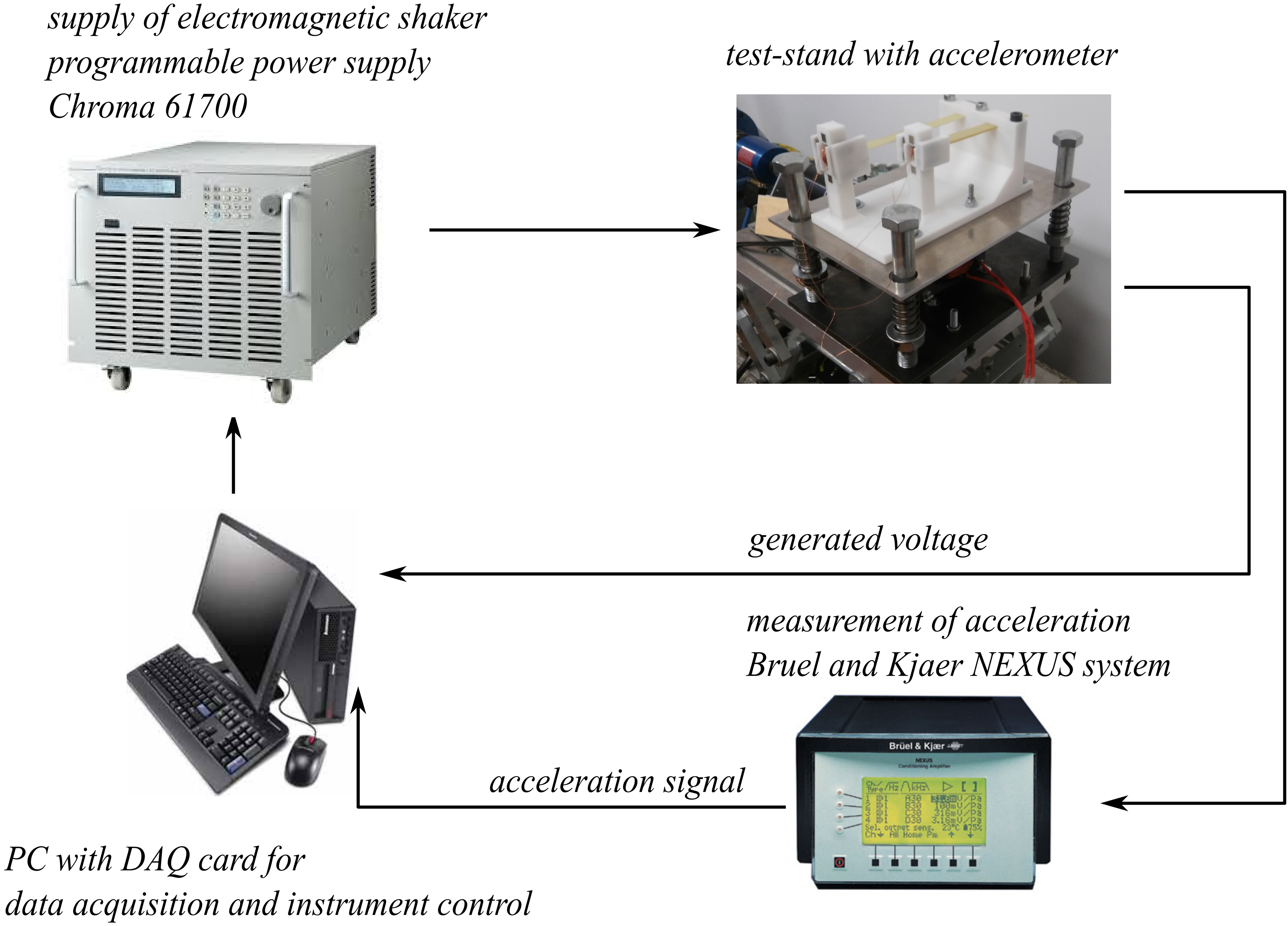
Figure 7.
Frequency characteristics of rms voltage across loading resistor for different loading conditions: a) HS harvester for rms value of force
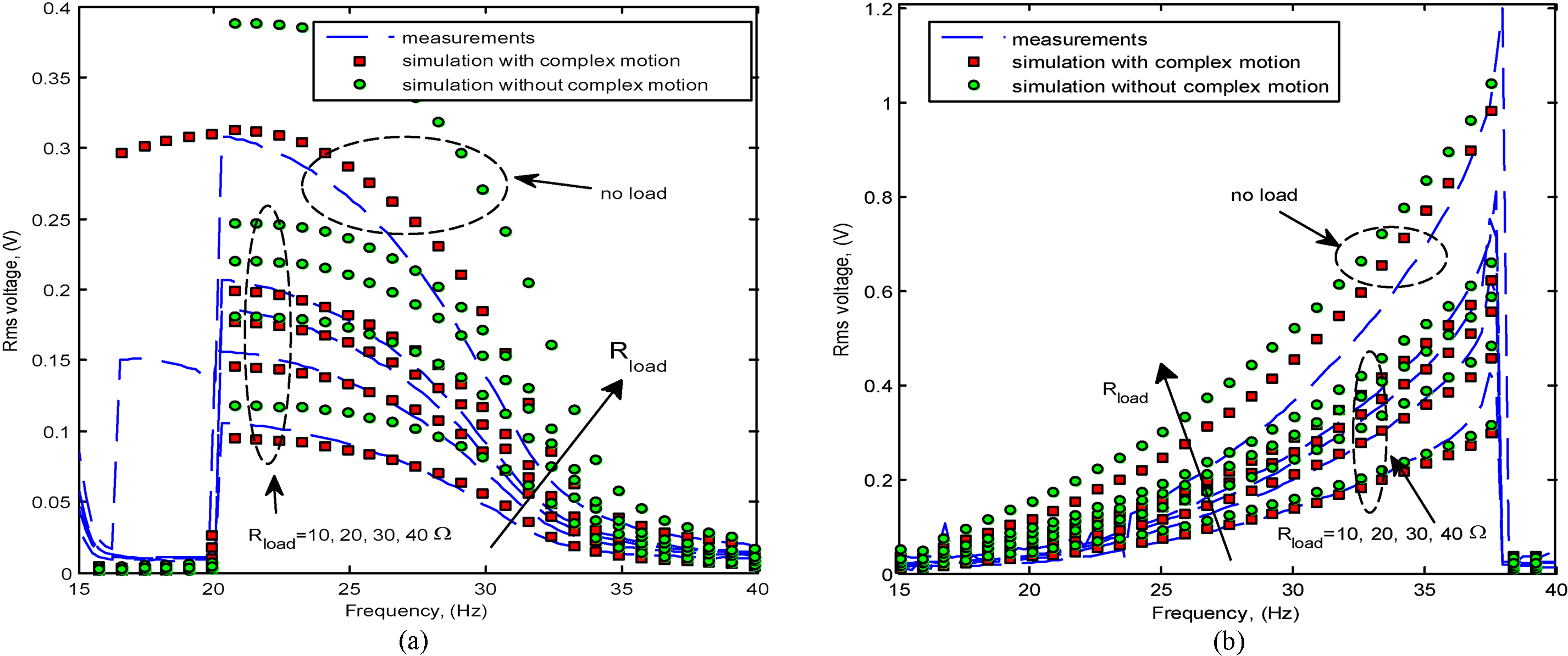
In the next step the characteristics were determined using the variations in Fig. 4 in Eqs (9)–(11). In order to validate the results the models were put under measurements on the laboratory test-stand (see Fig. 6). The simulated and measured characteristics for various loading conditions are presented in Fig. 7.
3.Discussion of results
The most important observations involving the results obtained for the two systems considered are, as follows.
For the HS harvester in Fig. 7a negligence of complex motion causes overestimation of generated voltage for all loading conditions. With the complex motion accounted for the results of simulation closely match the measurements except the no-load envelope which exposes more complex behavior in measurements between 15 Hz and 20 Hz. This however, can be easily explained by action of large harmonics in the experimental force waveform due to impact of the inertia force on the electromagnetic shaker. The results of additional simulations carried out for physically infeasible magnitudes of external force approaching to 0.5 N, which are not illustrated here, show that system with complex motion operating at no-load falls into chaotic operation around 18 Hz, whilst its simple-motion counterpart remains stable.
For the SU harvester in Fig. 7b negligence of complex motion also causes overestimation of simulated voltage. Simulations for larger and even physically infeasible magnitudes of external force, which are not illustrated here, exposed jump at frequency lower by some 2.2 Hz for the system with complex motion operating at no-load, although both were stable.
4.Conclusion
The investigation shows the need to account for the complex motion in a more accurate designing of the considered systems. The latter regards especially the HS-type system which exposes restricted stability and higher sensitivity to variations in conditions of operation than the SU-type one. Understanding these features is crucial from the viewpoint of development of a new type of wideband harvester integrating the HS and SU harvesters in a single system which will be presented in our future work.
Acknowledgments
The work was carried out under project 2016/23/N/ST7/03808 of The National Science Centre, Poland.
References
[1] | S.P. Beeby, R.N. Torah, M.J. Tudor, P. Glynne-Jones, T. O’Donnell, C.R. Saha and S. Roy, A micro electromagnetic generator for vibration energy harvesting, Journ. of Micromech. & Microeng., IOP Press, 17: (7) ((2007) ), 1257–1265. |
[2] | P. Podder, A. Amann and S. Roy, Combined Effect of Bistability and Mechanical Impact on the Performance of a Nonlinear Electromagnetic Vibration Energy Harvester, IEEE/ASME Trans. Mechatronics 21: (2) ((2016) ), 727–739. |
[3] | T. Sato and H. Igarashi, A chaotic vibration energy harvester using magnetic material, Smart Mater. Struct. 24: (2) ((2015) ), 25033. |
[4] | S.M. Chen, J.J. Zhou and J.H. Hu, Experimental study and finite element analysis for piezoelectric impact energy harvesting using a bent metal beam, Int, Journ. of Applied Electromagnetics and Mechanics, IOS Press, 46: (4) ((2014) ), 895–904. |
[5] | E. Sardini and M. Serpelloni, An efficient electromagnetic power harvesting device for low-frequency applications, Sensors Actuators A: Physical. 172: (2) ((2011) ), 475–482. |
[6] | M. Jagiela and M. Kulik, Wideband electromagnetic converter of vibration energy into electric energy, Patent Application, Patent Office of The Republic of Poland, No. P420998, March, (2017) . |
[7] | A.J.M. Ferreira, Solid mechanics and its applications Vol. 157: Matlab codes for finite element analysis, Springer, Netherlands, (2009) . |
[8] | onelab.info, accessed 01.2018. |


