
Non-cascaded finite time control of PMSLM based on super-twisting observer
Abstract
A novel control strategy based on finite time control and super-twisting observer is proposed to improve the control performance and robustness for permanent magnet synchronous linear motor (PMSLM) drive system. First of all, the velocity-current single loop control which called non-cascade structure control is proposed by the finite time control, then the response velocity of the PMSLM drive system can be improved. Secondly, to improve the disturbance rejection performance, a super-twisting observer is designed to feedforward the load. Furthermore, the strictly convergence of the proposed control strategy is implemented. Finally, comparative simulations and experiments are designed on PI control, sliding mode control, and the proposed control method. Results demonstrate that the proposed method has better robustness and control performance.
1.Introduction
Due to simple structure and high thrust density, permanent magnet synchronous linear motor (PMSLM) [1] have attracted much attention in high-velocity and precise drives, which have been widely applied in railway [2], logistics and distribution [3], electromagnetic launch [4], industrial manufacturing [5] and so on. Despite these advantages, the transient performance and disturbance rejection performance of the PMSLM system are constrained by end effects, cogging effects, parameter perturbation, sensors errors, dead zone of the inverter, and load disturbance [6–8]. To overcome the above shortcomings, a lot of advanced control methods and disturbance rejection compensation strategies have been proposed, such as adaptive control [9], sliding mode control (SMC) [10], H-∞ control, model predictive control (MPC) [11], extended state observer (ESO) [12], sliding mode observer (SMO), etc.
Compared to the current and velocity separated controlled under the cascade control, the non-cascade control can realize the velocity-current single-loop control, then the bandwidth can be improved, the structure can be simplified and the parameters can be reduced [13]. However, transient response property and disturbance rejection performance are still need to be improved under the non-cascade control structure. The research of these two areas will be analyzed in the following.
On the one hand, lots of methods have been proposed to improve the transient performance. In [14], an improved predictive current control is proposed to enhance the current response velocity and the steady-state response. However, the velocity regulation performance has not been well considered. In [10], to deal with the control gain of the controller, an adaptive fuzzy fractional-order sliding-mode control strategy is proposed, which can decrease the chattering and improve the tracking performance. In [15], an adaptive jerk control and modified parameter estimation methods for the PMSLM servo system is investigated to improve the control accuracy and transient performance. In [16], an internal model control PID is designed to reduce the tracking error and ensure the disturbance rejection performance. In [17], an adaptive predictive model involved the disturbance and optimized current change rate coefficient is designed, solving the problem of the current regulation performance will be affected by the parameter variations. In [18], a SMC with a dynamic boundary layer is designed to improve the position tracking property, and a multi-kernel neural network is proposed to enhance the disturbance rejection performance.
In short, although lots of methods have been applied to enhance the performance of PMSLM, all based on cascade control structure, and as far as our knowledge, the non-cascade control has not been retrieved.
On the other hand, the disturbance rejection performance is another difficult issue for PMSLM. In [19], the parameter disturbance observer and load disturbance observer is proposed to overcome parameter mismatch and load thrust disturbance. However, more observers increase the complexity of the system. In [20], the lumped disturbances which contains parameters perturbation, non-modeled dynamics, and load thrust disturbance, are compensated by an adaptive disturbance observer. In [21], the problem of time-varying parameters and load changes of the PMSLM is solved by an active disturbance rejection control, in which a reduced-order extended state observer is proposed to compensate the disturbances. In [22], the position estimation error, timely and accurate estimation of the load disturbance, and rotor position are estimated and compensated by an ESO, by which the sensorless control performance can be improved greatly. In [23], the high-order super-twisting observer is proposed to deal with the state variables, and the efficiency and superiority can be enhanced. However, the higher the order of the observer, the greater the disturbance and steady-state error will be. In [24], to overcome the thrust ripple and the nonlinear friction of rolling guide, the linear ESO and the friction feedforward controller is investigated, then the slow-varying disturbance is compensated by the linear ESO, and the nonlinear friction is eliminated by the feedforward controller. Nevertheless, design difficulty is increased by the design of multiple observers.
In summary, as far as the research concerned, all the methods deal with the disturbances of cascade structure, which is not applicable to the non-cascade control structure.
To obtain higher response velocity [25], higher precision [26], and better disturbance rejection performance [27], finite-time control (FTC) has received a lot of attention. Compared with the exponential convergence of the extended state observer and the sliding mode observer, the super-twisting observer has faster convergence [28] and higher precision [29] for it is finite-time convergence.
To improve the disturbance rejection property and transient performance of the PMSLM system under the non-cascade control, finite-time control based on super-twisting disturbance observer is investigated. Compared with previous work, the novelty of this paper can be organized as follows.
Unlike the traditional control scheme in which the velocity and current are controlled separately, based on finite time control, a velocity-current single-loop control is controlled by a finite time control which realize the non-cascade control.
The mismatched disturbance of the PMSLM in non-cascade structure is compensated by a super-twisting observer, which improves the disturbance rejection performance.
The rigorous stability analysis about the proposed finite time control and super-twisting observer is implemented.
The rest of the parts are organized as follows. In Section 2, the non-cascade mathematical model of the PMSLM is established. In Section 3, the super-twisting observer and finite time controller are designed, and the rigorous stability analysis in implemented. Section 4 is the comparative simulations and experiments. Section 5 is the conclusion and future research direction.
2.The mathematical model
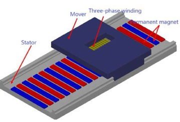
There are many types of PMSLM structures, the flat type linear motor and cylinder type linear motor are most widely used. The cylindrical linear motor has a larger thrust density but a shorter stroke, while the flat linear motor on the contrary. The experimental object of this paper is flat type linear motor, and its structure is shown in the Fig. 1. To facilitate the understanding of its working principle, it can be regarded as a permanent magnet synchronous motor (PMSM) cutting in the radial direction [30].
Fig. 1.
Schematic diagram of PMSLM.
The flux equation of the PMSLM under the vector control can be expressed as follows.
(1)
The d-axis and q-axis voltage equations can be expressed as follows.
(2)
For PMSLM, the three-phase current changes one cycle when the rotor goes through a pair of poles which the distance is 2𝜏, therefore the following can be obtain.
(3)
Further the electromagnetic thrust Fe can be expressed as follows.
(4)
Because a flat PMSLM’s permanent magnet is attached on the stator track which is similar to implicit pole PMSM, Ld = Lq, the above equation can be further simplified as follows.
(5)
The mechanical equation of PMSLM can be obtained as follows.
(6)
The equations of motion and voltage of simultaneous PMSLM can be expressed as follows.
(7)
3.Controller design
3.1.Super-twisting observer
From Eq. (7), the following we can obtain.
(8)
Taking d = FL as the estimated of load thrust, then the Eq. (8) can be re-written as follows.
(9)
Then the super-twisting observer can be designed for the load thrust disturbance as follows.
(10)
TheoremA .
− M ≤ d ≤ M,M is a constant, which means that the thrust of PMSLM has a maximum value. What’s more, due to the short sampling time, the sampling value is considered to be constant
Define the estimate error as
(11)
Define the vector
(12)
Construct the Lyapunov function as
(13)
The derivative of V with respect to time can be calculated as
(14)
(15)
Since A is Hurwitz, and 𝜆1 > 0, 𝜆2 > 0. For any Q = QT > 0, the solution P = PT > 0 can guarantee V be a strict Lyapunov function, which means that V > 0,
In addition, the convergence time and convergence region of the system can be expressed as
(16)
(17)
Furthermore, from the reference [31], it can be seen that the observed error e can be guaranteed to converge to zero in finite time when 𝜆1 and 𝜆2 are selected properly.
From the above analysis, it can be obtained that in a finite time,
3.2.Non-cascade structure finite time controller
From the Eq. (7) the following can be acquired.
Thus, the derivative of velocity v with respect to time can be expressed as follows.
(18)
Let x1 = vref − v, where vref is the reference velocity, we can have
(19)
The non-cascade structural controller in which the velocity and current is controlled by one controller as follows.
(20)
3.3.Convergence analysis
TheoremB .
For the system [32]
(21)
TheoremC .
For the system (18), if the vector function f (x) is homogeneous, the system is then called homogeneous [27].
From the Assumption 1,
Take the following Lyapunov function.
(22)
The derivative with respect to V can be obtained.
(23)
According to Eq. (23),
Besides, according to the homogeneous system definition, when r1 = 1,
(24)
Thus, the homogeneity of the system is
In summary, we know from Theorem 1 that the system ((19)) is finite time stable under the action of the finite time controller ((20)) and super twisting observer ((10)).
Fig. 2.
Control diagram of FTC-STO.
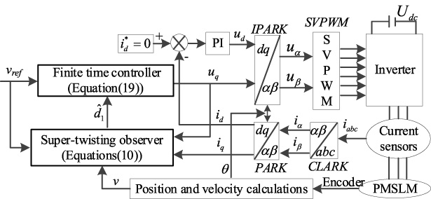
Table 1
The parameters of PMSLM
| Parameters | Values |
| d-axis reactance Ld | 4.4 mH |
| q-axis reactance Lq | 4.4 mH |
| Rotor mass | 30 kg |
| Coefficient of viscous friction | 152 N/(m/s) |
| Thrust of sliding friction | 42.5 N |
| Resistance R | 0.3 Ω |
| Pole pitch 𝜏 | 0.005 m |
| Flux linkage 𝜓f | 0.0891 Wb |
The PMSLM drive system framework is based on the proposed strategy is shown in Fig. 2.
4.Simulations and experiments
4.1.Simulations
In order to verify the effectiveness of the proposed method, the comparative simulations among traditional PI, SMC, and the proposed finite time control based super twisting observer (FTC-STO) are carried out. The PMSLM parameters used in the simulations are shown in Table 1. To ensure fairness, all simulation bus voltage is set as 36 V. Three groups of simulations are conducted, as described below.
The PI parameters of velocity controller can be designed as follows.
(25)
(26)
The PI parameters of current controllers can be designed as follows.
(27)
The parameters designed method of SMC is described as follows.
The sliding mode controller designed in this paper is expressed as follows.
Define the state variables as x1 = vref − v,
(28)
The whole contents can be written as follows.
(29)
The SMC controller and PI controller are analyzed by analogy. In SMC controller,
The parameters of q and c in SMC are designed according to the PI parameters calculated above.
(30)
The solutions of q and c can be obtained. And the switch coefficient 𝜂 is adjusted according to experience.
The SMC parameters is calculated as follows when the above methods are adopted.
The parameters of the proposed strategy can be designed as follows.
The order of magnitude relationship is similar to the traditional PID parameters. And the order of magnitude of
Although the parameters of sliding mode control, PI, and proposed method can be adjusted by the above method, the coefficients need to be adjusted according to the actual operation effect in the actual debugging.
The parameters used in the simulations are shown in Table 2, Table 3, and Table 4, respectively.
Table 2
The parameters of PI controller
| Parameters | Values |
| Velocity loop proportional gain | 50 |
| Velocity loop integral gain | 500 |
| Current loop proportional gain | 14.7 |
| Current loop integral gain | 1000 |
Table 3
The parameters of SMC controller
| Parameters | Values |
| c in the SMC | 10 |
| 𝜂 in the SMC | 0.1 |
| q in the SMC | 100 |
| Current loop proportional gain | 14.7 |
| Current loop integral gain | 1000 |
Table 4
The parameters of FTC-STO
| Parameters | Values |
| k1 | 7 × 10⁶ |
| k2 | 8 × 10³ |
| 𝛼1 | 0.6 |
| 𝛼2 | 0.75 |
| 𝜆1 | 2 × 10³ |
| 𝜆2 | 6 × 10⁷ |
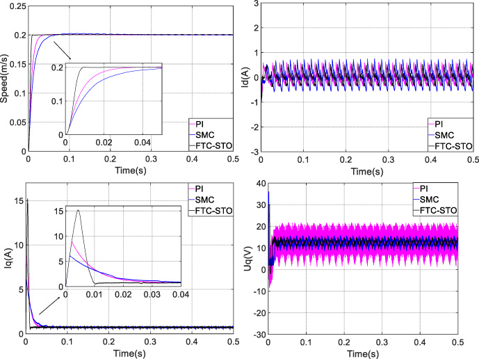
The first group is the step response comparison, PMSLM starts initially with 2 N load, and the reference velocity is 0.2 m/s. Figure 3 shows the step response comparison curves of the two algorithms including the response curve of the d-axis current id, q-axis current iq, q-axis voltage uq and velocity v. PI control takes 0.11 s reaching steady state and have 0.0215 overshoot. FTC-STO takes 7.3 × 10⁻³ s reaching steady state without any overshoot. The comparative results show that FTC-STO can achieve the reference velocity faster than PI, and the fluctuation of q-axis voltage and current is less.
Fig. 3.
Initial startup comparison of the two algorithms.
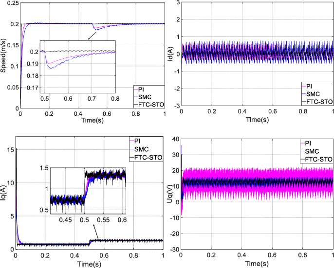
The second group is the contrast of loading in steady state. The load changes from 2 N to 8 N after 0.5 s when PMSLM reaches steady state of 0.2 m/s. Figure 4 shows the response curves of the two algorithms respectively including the velocity, id and uq. As a result, we can obtain that the velocity decline value of FTC-STO is smaller than that of PI and the recovery velocity is faster than that of PI respectively.
Fig. 4.
The loading comparison results of the two algorithms.
The third group is a sinewave tracking comparison. The given reference velocity curve is 0.2sin(2𝜋t ×10), PMSLM starting with loading. Figure 5 shows the response comparison curves of the two algorithms respectively including the response curve of the d-axis current id, q-axis current iq, q-axis voltage uq and velocity v. It can be observed from Fig. 5, compared to PI and SMC, the reference velocity can be better tracked by FTC-STO, and the amplitude and phase can be followed accurately, which verified that the FTC-STO has higher bandwidth than PI and SMC.
Fig. 5.
The response comparison curves of the two algorithms.
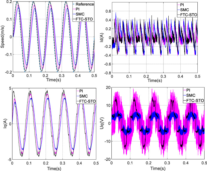
Table 5 list the comparative results about PI, SMC, and FTC-STO. It can be illustrated that FTC-STO has a better robustness and disturbance rejection performance.
4.2.Experiments
For further validation, comparative experiments are implemented on PI, SMC and the proposed strategy.
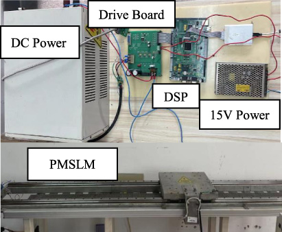
The PMSLM control experimental platform is shown in Fig. 6. The control part includes a DSP main control board, an inverter drive board, a DC adjustable power supply, a 15 V auxiliary switch power supply, and a grating ruler. The DSP main control board is powered by a 5 V power adapter, and the inverter drive board is powered by a 15 V switch power supply. The bus voltage is 33 V, and the grating ruler resolution is 5 μm. The controlled object is a PMSLM, using a 5 kg standard weight as the load.
Table 5
The performance of the controllers
| Algorithms | Steady-state time | Velocity decreased | Recovery to steady-state | Fluctuation of q-axis current | Fluctuation of q-axis voltage |
| PI | 0.03 s | 0.01 m/s | 0.3 s | 0.25 A | 18 V |
| SMC | 0.04 s | 0.012 m/s | 0.3 s | 0.25 A | 3.5 V |
| FTC-STO | 0.01 s | 0.001 m/s | 0.0001 s | 0.35 A | 3 V |
Fig. 6.
The experimental platform.
As can be seen from the performance comparison curves of the three control methods in Fig. 7, the FTC-STO control method proposed in this paper can reach the reference velocity faster than the traditional SMC and PID control method in the PMSLM startup phase without overshoot. The d-axis controller adopts PID controller with the same parameter setting. The amplitude of the d-axis current of FTC-STO is obviously smaller than that of SMC and PID. By comparing the q-axis response curves, it can be seen that the q-axis current of FTC-STO reaches the steady-state value faster than the traditional SMC and PID controller. Moreover, the chattering amplitude of q-axis current is significantly lower than that of SMC and PID controller. As can be seen from A-phase current comparison curves, phase current chattering of FTC-STO control strategy is smaller than SMC and PID controller.
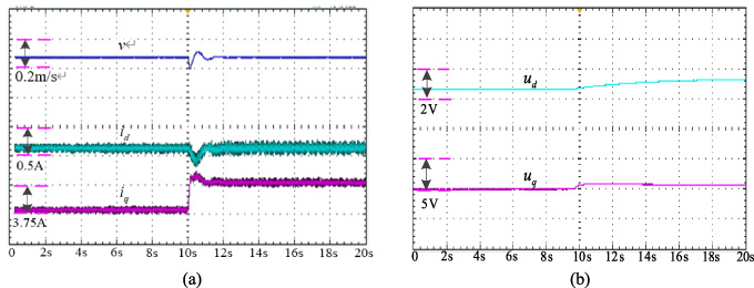
Fig. 7.
The experiment curves of FTC-STO. (a) Velocity, id, iq; (b) ud, uq.
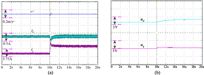
Fig. 8.
The experiment curves of SMC. (a) Velocity, id, iq; (b) ud, uq.
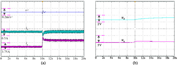
When load sudden change, it can be seen from figure that the velocity of the PID controller will be from the steady-state value of 0.2 m/s to increase or decrease of 0.014 m/s, SMC from steady-state value at a velocity of 0.2 m/s to increase or decrease of 0.017 m/s, and FTC-STO from steady-state value at a velocity of 0.2 m/s to increase or decrease 0.019 m/s, and FTC-STO control method to a steady velocity need only 0.0003 s, SMC and PID control methods will need 0.06 s to restore the steady-state velocity, which verifies that the method proposed in this paper greatly improves the velocity tracking performance of PMSLM. Similarly, the d-axis current, q-axis current and A-phase current of FTC-STO have less jitter than SMC and PID controllers. Compared with SMC and PID controller, q-axis current of PMSLM controlled by FTC-STO reaches steady-state current value more quickly.
It can be seen from Figs 7–9 that the response curves of FTC-STO are faster than SMC and PI, including velocity, d-axis current, q-axis current, q-axis voltage, which verified that the proposed control strategy has a better disturbance.
Fig. 9.
The experiment curves of PI. (a) Velocity, id, iq; (b) ud, uq.
5.Conclusion
A finite time controller is designed to directly adjust the velocity loop of PMSLM under the non-cascade structure. Based on this, a super-twisting observer was developed to increase the anti-disturbance performance. The simulation result shows that proposed method has fast tracking velocity, no overshoot and better disturbance rejection. The non-cascade structure control method is adopted to improve the bandwidth of the controller. As a consequence of lots of parameters and broad bandwidth, it was very important for engineering applications to know how to design parameters in a way that was both accurate and based on theory. The control performance will be seriously restricted by the multi-sources disturbances of the PMSLM system, so future we will deal with the simultaneous cancellation for them.
Acknowledgements
This research work was supported by National Natural Science Foundation of China (42176211), Jiangsu Province Natural Science Foundation Youth Fund (BK20220610).
References
[1] | Z. Zhang, M. Luo, J.-a. Duan , Design and analysis of a novel frequency modulation secondary for high-velocity permanent magnet linear synchronous motor, IEEE/ASME Transactions on Mechatronics 27: (2) ((2022) ), 790–799. |
[2] | Z. Zheng, J. Zhao, L. Wang , Efficient optimization design method of PMSLM based on deep adaptive ridge regression with embedded analytical mapping function, IEEE Transactions on Industrial Electronics 69: (8) ((2022) ), 8243–8254. |
[3] | J. Zhao, Y. Zhou, J. Zhao , Mover position detection for PMSLM based on line-scanning fence pattern and subpixel polynomial fitting algorithm, IEEE/ASME Transactions on Mechatronics 25: (1) ((2020) ), 44–54. |
[4] | C. Zhang, F. Chen, S. Qiu , A low detent force DS-PMSLM based on the modulation of cogging and end forces, IEEE Transactions on Industrial Electronics 70: (1) ((2023) ), 721–730. |
[5] | Y. Zhang, X. Huang, A. Wang , A position and velocity controller tuning method of permanent magnet synchronous linear motor based on gain identification, IEEE Transactions on Power Electronics 37: (10) ((2022) ), 11716–11724. |
[6] | Z. He, F. Dong, J. Zhao , Thrust ripple reduction in permanent magnet synchronous linear motor based on tuned viscoelastic damper, IEEE Transactions on Industrial Electronics 66: (2) ((2019) ), 977–987. |
[7] | L. Wang, J. Zhao, X. Yang , Robust deadbeat predictive current regulation for permanent magnet synchronous linear motor drivers with parallel parameter disturbance and load observer, IEEE Transactions on Power Electronics 37: (7) ((2022) ), 7834–7845. |
[8] | J.H. Kim, S.W. Jung, Y.S. Kwon, S. Lee and J.Y. Yoon, Modeling of current-driven end-effect force ripple in air-cored linear synchronous motor with multiple modular stators, IEEE Transactions on Industrial Electronics 70: (11) ((2023) ), 11507–11515, doi:10.1109/TIE.2022.3227289. |
[9] | F.F.M. El-Sousy and K.A. Abuhasel, Nonlinear robust optimal control via adaptive dynamic programming of permanent-magnet linear synchronous motor drive for uncertain two-axis motion control system, IEEE Transactions on Industry Applications 56: (2) ((2020) ), 1940–1952. |
[10] | S.-Y. Chen, H.-H. Chiang, T.-S. Liu , Precision motion control of permanent magnet linear synchronous motors using adaptive fuzzy fractional-order sliding-mode control, IEEE/ASME Transactions on Mechatronics 24: (2) ((2019) ), 741–752. |
[11] | Z. Li, J. Wang, J. An , Control strategy of biaxial variable gain cross-coupled permanent magnet synchronous linear motor based on MPC-MRAS, IEEE Transactions on Industry Applications 58: (4) ((2022) ), 4733–4743. |
[12] | J. Lin, S. Zhang, L. Zhou , Improved sliding mode control of permanent magnet synchronous linear motor based on model-assisted linear extended state observer, IEEE Access 10: ((2022) ), 70815–70824. |
[13] | Y. Wang, H. Yu and Y. Liu, Velocity-current single-loop control with overcurrent protection for PMSM based on time-varying nonlinear disturbance observer, IEEE Transactions on Industrial Electronics 69: (1) ((2022) ), 179–189. |
[14] | M. Wang, L. Li, D. Pan , High-bandwidth and strong robust current regulation for PMSLM drives considering thrust ripple, IEEE Transactions on Power Electronics 31: (9) ((2016) ), 6646–6657. |
[15] | H. Yuan and X. Zhao, Adaptive jerk control and modified parameter estimation for PMSLM servo system with disturbance attenuation ability, IEEE/ASME Transactions on Mechatronics 28: (1) ((2023) ), 164–174. |
[16] | Y. Liu, J. Gao, Y. Zhong , Extended state observer-based IMC-PID tracking control of PMSLM servo systems, IEEE Access 9: ((2021) ), 49036–49046. |
[17] | F. Wang, L. He, J. Kang , Adaptive model predictive current control for PMSLM drive system, IEEE Transactions on Industrial Electronics 70: (4) ((2023) ), 3493–3502. |
[18] | P. Wang, Y. Xu, R. Ding , Multi-kernel neural network sliding mode control for permanent magnet linear synchronous motors, IEEE Access 9: ((2021) ), 57385–57392. |
[19] | L. Wang, J. Zhao, X. Yang , Robust deadbeat predictive current regulation for permanent magnet synchronous linear motor drivers with parallel parameter disturbance and load observer, IEEE Transactions on Power Electronics 37: (7) ((2022) ), 7834–7845. |
[20] | C. Bai, Z. Yin, Y. Zhang , Multiple-models adaptive disturbance observer-based predictive control for linear permanent-magnet synchronous motor vector drive, IEEE Transactions on Power Electronics 37: (8) ((2022) ), 9596–9611. |
[21] | M. Li, J. Zhao, Y. Hu , Active disturbance rejection position servo control of PMSLM based on reduced-order extended state observer, Chinese Journal of Electrical Engineering 6: (2) ((2020) ), 30–41. |
[22] | Y. Xu, C. Lin and J. Xing, Transient response characteristics improvement of permanent magnet synchronous motor based on enhanced linear active disturbance rejection sensorless control, IEEE Transactions on Power Electronics 38: (4) ((2023) ), 4378–4390. |
[23] | D. Xu, B. Ding, B. Jiang , Nonsingular fast terminal sliding mode control for permanent magnet linear synchronous motor via high-order super-twisting observer, IEEE/ASME Transactions on Mechatronics 27: (3) ((2022) ), 1651–1659. |
[24] | X. Liu, H. Cao, W. Wei , A practical precision control method base on linear extended state observer and friction feedforward of permanent magnet linear synchronous Motor, IEEE Access 8: ((2020) ), 68226–68238. |
[25] | C. Zhang, Y. Yan, A. Narayan , Practically oriented finite-time control design and implementation: Application to a series elastic actuator, IEEE Transactions on Industrial Electronics 65: (5) ((2018) ), 4166–4176. |
[26] | S. Ding, K. Mei and S. Li, A new second-order sliding mode and its application to nonlinear constrained systems, IEEE Transactions on Automatic Control 64: (6) ((2019) ), 2545–2552. |
[27] | J. Yang, W.-H. Chen, S. Li , Disturbance/uncertainty estimation and attenuation techniques in PMSM drives—A survey, IEEE Transactions on Industrial Electronics 64: (4) ((2017) ), 3273–3285. |
[28] | X. Xiong, Z. Liu, S. Kamal , Discrete-time super-twisting observer with implicit Euler method, IEEE Transactions on Circuits and Systems II: Express Briefs 68: (4) ((2021) ), 1288–1292. |
[29] | Q. Hou and S. Ding, Finite-time extended state observer-based super-twisting sliding mode controller for PMSM drives with inertia identification, IEEE Transactions on Transportation Electrification 8: (2) ((2022) ), 1918–1929. |
[30] | Y. Zhang, X. Huang, A. Wang , A position and velocity controller tuning method of permanent magnet synchronous linear motor based on gain identification, IEEE Transactions on Power Electronics 37: (10) ((2022) ), 11716–11724. |
[31] | J.A. Moreno and M. Osorio, Strict Lyapunov functions for the super-twisting algorithm, IEEE Transactions on Automatic Control 57: (4) ((2012) ), 1035–1040. |
[32] | S.P. Bhat and D.S. Bernstein, Finite-time stability of continuous autonomous systems, SIAM Journal on Control and Optimization 38: (3) ((2000) ), 751–766. |


