
Coupled design approach for an integrated GaN-based wireless power transfer rotating system
Abstract
This paper concerns the design of a high-frequency GaN-based rotating transformer confined by conductive materials. The design approach combines the high-order spectral element method for the magnetic modeling, an electronic circuit model, and the finite element method for the thermal modeling. The objective of the design analysis is to minimize the ratio of core inertia to efficiency. Two different transformer topologies are considered, in which the power is either transferred in the axial or radial direction. The resulting designs are compared in terms of efficiency, core inertia, and transferred power. The radial design shows the best performance within the optimization problem.
1.Introduction
Wireless power transfer (WPT) by means of an inductive coupling is widely applied in applications where reliable power transfer across rotating parts is required, e.g. in aerospace and medical applications, as well as a replacement for slip rings in electrical machines [1,2]. Typically, a highly permeable cylindrical transformer is used, where the primary and secondary side are separated by an air gap in either the axial or radial direction. The performance is enhanced by applying a high-frequency power supply, additionally resonance techniques can be employed [3,4]. Gallium-Nitride (GaN) transistors are emerging in WPT applications, since switching frequencies in the range of several MHz are realized compactly and efficiently [5,6].
The design of an integrated high-frequency WPT system can be challenging, especially in applications where restrictions on the field penetration into surrounding objects are of importance [7,8]. Consequently, shielding techniques are applied in order to mitigate undesirable effects of the magnetic field. Inclusion of the shielding technique in the design phase is crucial, since the performance might degrade significantly [9].
The finite element method (FEM) is often applied during the design phase [1–4,7,8]. However, for high-frequency applications in which the skin-depth is several orders of magnitude smaller compared to the model dimensions, the locally different requirements on the mesh density cause meshing problems [10,11]. In order to overcome this problem, the conductive regions are often replaced by surface impedance boundary conditions (SIBCs). The discrepancy introduced by a SIBC is dependent on the relation of the radius to the skin-depth [12,13], thus SIBCs are not applicable to any arbitrary problem. Furthermore, a SIBC is unable to obtain the magnetic field distribution inside the conductive region. Alternatively, for this type of problem, higher-order methods can be applied, such as the spectral element method (SEM), which with respect to the FEM, can provide superior accuracy at the expense of geometrical domain flexibility [14,15].
The SEM is being applied to a wide variety of engineering and research disciplines, e.g. seismology, waveguide analysis, and electrical machines [16–18]. The formulation of the SEM for magneto-static problems was presented in [15]. In [18], the formulation was applied for the magnetic modeling of a linear synchronous actuator. In [10], a single spectral element was used to model the losses induced in a high-speed rotating cylinder. In [19], it was demonstrated that by applying the SEM for the magnetic modeling of a high-frequency eddy current problem, with respect to the FEM, a higher accuracy per degree of freedom and lower computation time were obtained. In [11], a coupled FEM-SEM approach was applied to an induction machine, where the SEM was used for the non-linear modeling of eddy current losses in the rotor, and the FEM was used for the remaining machine parts. In [20], a coupled FEM-SEM approach was applied for the investigation of magneto-convection for transformer cooling.
In this paper, the SEM is applied for the magnetic modeling and design of a high-frequency rotating transformer confined by conductive materials. The design approach is complemented by a thermal FEM model, and an electrical circuit model. The objective is to minimize the ratio of core inertia to efficiency. Two different transformer topologies are considered, having a varying air gap construction. Furthermore, a frequency range up to and including 1 MHz is considered, by the application of a GaN half-bridge inverter.
Fig. 1.
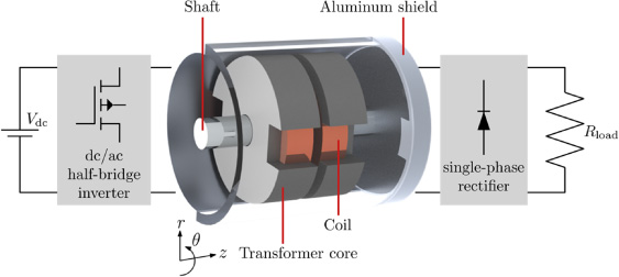
Schematic system overview, including indication of components. For visualization purposes, the aluminum shield is partially transparent.
2.System overview
A schematic overview of the WPT system is shown in Fig. 1. The system consists of a dc supply (48 Vdc), a high-frequency dc/ac GaN half-bridge inverter, which supplies the primary coil of a cylindrical transformer (consisting of a set of coils, each of which is placed inside an individual magnetic core). The secondary coil is connected to a single-phase rectifier and finally to a load. The secondary side of the transformer will be mounted to a stainless-steel shaft, whereas the primary side will be mounted to an aluminum shield, which surrounds the design space. The system is required to have a constant output voltage (independent of the load), which is an advantageous feature for achieving good controllability [21].
The two investigated transformer topologies are shown in Fig. 2, the corresponding fixed geometrical parameters (the remaining parameters are determined through a design optimization) and linear material properties are shown in Table 1. The mechanical connections indicated in the figure are assumed to be magnetically and thermally equivalent to air. The power is either transferred in the axial or radial direction, which corresponds to the geometry shown in Figs 2(a) and 2(b), respectively. The topology shown in Fig. 2(a), is also included in the system overview shown in Fig. 1 and is most commonly referred to as a pot core transformer. In this paper, the topologies are henceforth referred to as axial and radial topology, corresponding to the direction of power transfer. Both transformer topologies have been discussed and applied in WPT systems in various research papers for a wide range of frequencies, power levels, and applications [4,22–27].
Fig. 2.
Investigated transformer topologies including aluminum shield, stainless-steel shaft, element discretization, material properties, geometrical parameters, and boundary conditions (magnetic and thermal). The direction of power transfer is either in (a) the axial, or (b) the radial direction.
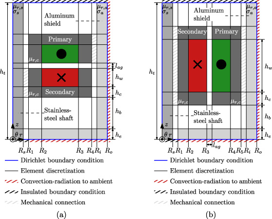
Table 1
Fixed geometrical parameters and material properties
| Geometrical parameters | |||
| Parameter | Symbol | Value | Unit |
| Outer radius stainless-steel shaft | Rs | 1.50 | mm |
| Inner radius aluminum shield | Ri | 7.50 | mm |
| Outer radius aluminum shield | Ro | 8.50 | mm |
| Air gap length | lag | 0.50 | mm |
| Axial height aluminum shield | he | 4.00 | mm |
| Axial height full domain | ht | 22.5 | mm |
| Material properties | |||
| Quantity | Symbol | Value | Unit |
| Relative permeability core | 𝜇r, c | 2300 | - |
| Relative permeability aluminum | 𝜇r, a | 1.00 | - |
| Relative permeability stainless-steel | 𝜇r, s | 1.00 | - |
| Electric conductivity aluminum | 𝜎a | 3.77 × 10⁷ | S∕m |
| Electric conductivity stainless-steel | 𝜎s | 1.45 × 10⁶ | S∕m |
| Core iron loss parameter | Cm | 10.6 | W ⋅ s𝛼∕T𝛽 ∕m3 |
| Core iron loss parameter | 𝛼 | 1.30 | - |
| Core iron loss parameter | 𝛽 | 2.70 | - |
| Strand radius | rs | 0.016 | mm |
| Number of strands | ns | 250 | - |
| Nominal dc resistance (20 °C) | Rdc,0 | 0.0987 | Ω∕m |
The axial topology offers a number of advantages with respect to the radial topology. Firstly, the geometries of the primary and secondary side are symmetrical, which is advantageous for large-scale production. Secondly, a wide variety of core sizes is commercially available [28]. Thirdly, the axial topology is favorable in terms of magnetic coupling and losses [29]. Consequently, the axial topology is more frequently applied in WPT systems. However, a major drawback of the axial transformer occurs in case the transformer is integrated in the design space shown in Fig. 2, since the aluminum shield and stainless-steel shaft are directly positioned in the fringing-flux paths parallel to the air gap. As a result, significant eddy current losses are expected to be induced. As a result of the different air gap construction in the radial topology, the fringing-fluxes will induce significantly lower losses in the surrounding materials. An additional advantage of the different air gap construction of the radial transformer is that the secondary side naturally occupies a smaller radius. Therefore, the radial topology, the radial topology is expected to have a lower core inertia, which is an important characteristic for a rotating system.
3.Design models
Both transformer topologies are designed by adopting a multi-physical approach, consisting of coupled magnetic, electrical, and thermal models, which is comparable to the design approach discussed in [22].
3.1.Magnetic
In order to obtain the magnetic field solution, the investigated domain is discretized into rectangular elements and a Dirichlet boundary condition is applied to the domain boundaries (by assuming perfect shielding), as shown in Fig. 2. The nodal Galerkin approximation is applied to obtain the solution of the diffusion equation in the frequency domain in each element, which is given by
(1)
Legendre–Gauss–Lobatto polynomials are applied for the local approximation of the magnetic field. The degree of the polynomial directly relates to the number of grid points in an element. The accuracy of the results can be improved by increasing the polynomial degree, i.e. p-refinement. This feature is particularly useful for solving high-frequency eddy current problems where a high ratio between the object dimensions and the skin-depth exists [19]. Furthermore, the SEM applies Gaussian quadratures in order to perform numerical integration, whereas divergence operators are evaluated using Lagrangian basis functions. Additional details on the formulation and implementation of the method can be found in [14,15,19,31].
Fig. 3.
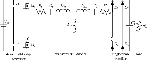
Electrical equivalent circuit model of the wireless power transfer system, including indication of the various components.
From the resulting magnetic field solution, the self- and mutual-inductances of the coils are obtained, which serve as an input to the electrical circuit model. Furthermore, the eddy current losses in the conductive regions are calculated as
(2)
(3)
3.2.Electrical
The electrical equivalent circuit model of the system is shown in Fig. 3, which is based on the transformer T-model, consisting of the magnetizing inductance, leakage inductances, and the coil resistances. The components on the secondary side are reflected to the primary side through the winding ratio. Resonant capacitors are added in series with the coils, such that the leakage inductances are compensated and a load independent output voltage is created [21]. The required primary and secondary capacitances are calculated as
(4)
(5)
Additionally, Litz wire is used in the coils, such that the losses caused by the skin and proximity effect are minimized. The additional losses as a result of these effects are approximated in the model by the ac resistance, which is obtained by scaling the dc resistance according to
(6)
(7)
(8)
The electrical circuit model is solved by the LT-Spice circuit simulator [37]. Non-ideal device models of the GaN transistors and Schottky diodes are included in the model [38,39]. The switches are controlled by a square-wave gate signal. From the circuit simulation, the output power and losses are obtained, i.e. Joule, switch, and diode losses, where the Joule losses serve as an input to the thermal model.
Table 2
Optimum axial and radial transformer topologies
| Geometrical design | |||||
| Parameter | Symbol | Benchmark | Axial | Radial | Unit |
| First core radius | R1 | 1.60 | 1.69 | 1.61 | mm |
| Second core radius | R2 | 2.95 | 2.71 | 2.62 | mm |
| Third core radius | R3 | 5.90 | 5.22 | 4.13 | mm |
| Fourth core radius | R4 | 7.00 | 6.22 | 6.21 | mm |
| Fifth core radius | R5 | - | - | 7.30 | mm |
| Winding area height | hw | 2.80 | 5.93 | 4.38 | mm |
| Tooth height | hc | 1.10 | 1.02 | 1.02 | mm |
| Core inertia | Jc | 46.4 | 47.2 | 5.70 | g ⋅ mm2 |
| Primary core volume | Vp | 0.339 | 0.412 | 0.408 | cm3 |
| Secondary core volume | Vs | 0.339 | 0.412 | 0.151 | cm3 |
| Transformer design | |||||
| Parameter | Symbol | Benchmark | Axial | Radial | Unit |
| Frequency | f | 1000 | 1000 | 950 | kHz |
| Number of primary turns | Np | 6 | 12 | 5 | — |
| Number of secondary turns | Ns | 7 | 13 | 6 | — |
| Magnetizing inductance | Lm | 1.65 | 5.27 | 1.55 | 𝜇H |
| Primary leakage inductance | Llkp | 0.481 | 3.81 | 0.170 | 𝜇H |
| Secondary leakage inductance | 0.481 | 3.81 | 0.129 | 𝜇H | |
| Primary resonant capacitance | Cp | 53.0 | 6.70 | 170 | nF |
| Secondary resonant capacitance | 53.1 | 6.69 | 216 | nF | |
| Physical quantities | |||||
| Quantity | Symbol | Benchmark | Axial | Radial | Unit |
| Output power | Po | 30.9 | 26.3 | 33.1 | W |
| Efficiency | 𝜂 | 93.4 | 95.2 | 96.2 | % |
| Primary current | Ip | 2.43 | 1.33 | 2.37 | Arms |
| Secondary current | Is | 1.28 | 1.18 | 1.36 | Arms |
| Primary resonant capacitor voltage | Vc, p | 25.7 | 40.3 | 24.9 | Vrms |
| Secondary resonant capacitor voltage | Vc, s | 5.29 | 33.2 | 1.63 | Vrms |
| Peak flux density primary core | 127 | 142 | 74.7 | mT | |
| Peak flux density secondary core | 91.5 | 104 | 184 | mT | |
3.3.Thermal
The iron losses, Joule losses in the windings, and eddy current losses in the conductive materials, cause the temperature of the domain to rise. In order to approximate this temperature rise, a thermal model is employed. Under the assumption that, the heat sources are uniform within their respective elements, the advantage of applying the SEM is less evident, since the locally different requirements on the mesh density have vanished. Therefore, in the thermal model, the FEM is applied, which is solved by commercial software (Altair Flux) [40].
In order to create a worst-case scenario, the exchange of heat between the various elements can only take place by means of conduction. Furthermore, on the top axial boundary of the domain, a thermally insulated boundary condition is included, and the effect of rotation is neglected. Heat transfer as a result of convection and radiation to the ambient environment is included on the boundaries of the domain. The thermal boundary conditions are included in Fig. 2. The convection coefficient at the boundaries is given by
(9)
(10)
The thermal model is solved iteratively, updating the heat transfer coefficients and coil resistances at every iteration until steady state conditions are reached. Additionally, the thermal conductivity of the air in an element is recalculated at every iteration according to
(11)
4.Design optimization
Two different design optimizations are considered. First, a standard P14/8 pot core geometry [28] (i.e. the axial topology) is optimized for maximized efficiency. The optimum design will serve as the benchmark design. Second, both the axial and radial topologies are considered in a full geometrical optimization, in order to determine the optimum design and improvement over the commercially available design. In this case, the objective is to minimize the ratio of core inertia to efficiency (i.e. minimizing the former, while maximizing the latter). In both cases an output power of at least 25 W is required.
4.1.Benchmark topology
In order to ensure the validity of the design, constraints on the peak value of the magnetic flux density in a core element, average value of the temperature in an element, and electrical load in the power electronic components are added. In order to ensure that the system is classifiable as a low-voltage system, the rms voltage across the resonant capacitors is limited to 48 V. The optimization problem is given by
(12)
4.2.Geometrical optimization
For the full geometric optimization, the geometrical parameters defining the two transformer geometries are added to the set of design variables. The objective is changed to minimize the core inertia to efficiency ratio. The constraints as shown in (12) remain unchanged, however additional constraints on the geometrical parameters are added, such that a feasible geometry is ensured. Furthermore, the values of the fixed geometrical parameters, material properties, load resistance and ambient temperature remain unchanged. The optimization problem, excluding the unchanged constraints, is given by
(13)
Fig. 4.
Contour plots of the magnetic vector potential and temperature distribution in the domain including indication of the geometry: (a) benchmark, (b) axial, and (c) radial design.
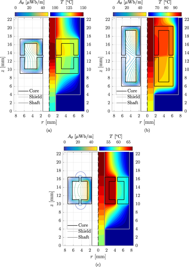
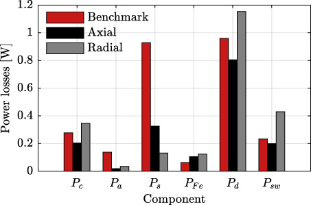
Fig. 5.
Separation of power losses for the benchmark, axial, and radial design; Joule losses in the windings (Pc), eddy current losses in the aluminum shield (Pa) and stainless-steel shaft (Ps), iron losses in the core (PFe), diode losses (Pd), and switching losses (Psw), respectively.
The design analysis is conducted using a gradient-based optimization algorithm, which is evaluated for several different initial points. As a result of the transformer winding ratio being a discrete variable, the required number of primary and secondary turns is computed in a parametric search loop within the electrical model.
5.Results
The benchmark geometry and the two resulting optimum geometries together with contour plots of the magnetic vector potential and temperature distribution in the domain are shown in Fig. 4. The corresponding geometrical parameters, transformer designs, and physical quantities are shown in Table 2. The contribution of the various loss components to the overall power losses for all designs are shown in Fig. 5. As a result of the benchmark design being integrated closely to the shaft, a significant amount of eddy current losses are induced in the shaft, as shown in Fig. 5. Consequently, the temperature constraint is not satisfied, as shown in Fig. 4(a). In the geometrical optimization, the inertia is minimized by the minimization of the core radii. However, for the axial design, the thermal limit poses a lower bound on the inner core radius (R1), as a result of high eddy current losses being induced in the shaft. The total available axial space is occupied by the axial design, such that a high number of turns can be fitted and a high magnetizing inductance is obtained, while the outer core radius (R4) is minimized for the required output power level. The large axial height and small radial depth of the transformer, results in high leakage inductances, as shown in Fig. 4(b) and Table 2. The high leakage inductances are compensated by resonant capacitors. In case of the radial topology, the different air gap construction results in low eddy current losses being induced in the shaft and shield regions, as shown in Fig. 5. Consequently, contrary to the axial topology the minimization of the core inertia (and consequently the core radii), is not limited by the thermal constraints, as shown in Fig. 4(c). However, the small available radial depth and tight constraints largely define the geometry in the radial direction. Therefore, the optimization is mainly determined by the winding area height.
As a result of the transfer of power being more efficient at higher frequencies, in all three cases the optimum design is obtained at approximately the maximum electrical frequency; 1.0 MHz for the benchmark and axial designs, whereas for the radial design the optimum is obtained at 950 kHz. The benchmark design is the least favorable design, as a result of the high temperatures and relatively low efficiency, thus demonstrating the advantages of the custom topologies. The radial design is the preferred design in terms of efficiency, output power, and core inertia. With respect to the benchmark design, the radial design improves the efficiency, output power, and core inertia by 2.8%, 7.1%, and 88%, respectively, whereas with respect to the axial design, the quantities are improved by 1.0%, 26%, and 88%, respectively. The radial design reaches the highest output power, as a result of the discrete step in the winding design.
6.Conclusions
A multi-physical design approach for high-frequency rotating transformers encapsulated by conductive materials has been proposed. The design approach couples different physical domains, i.e. magnetic, electrical, and thermal. The magnetic model employs the high-order SEM, which allows for efficient and accurate calculation of the eddy current losses, especially for problems where the skin-depth is several orders of magnitude smaller compared to the model dimensions. The electrical model employs a Spice circuit simulator, such that the losses in the power electronic components are approximated. Finally, the design approach is complimented by a FEM model for the calculation of the temperature rise in the investigated domain.
Two different transformer topologies were considered, in which as a result of the air gap construction, the power is either transferred in the axial or radial direction. Both transformer topologies are enclosed by a stainless-steel shaft and aluminum shield. Two different design optimizations were carried out, first a benchmark design was established by maximizing the efficiency of an industry standard axial transformer, i.e. the P14/8 pot core. Second, a geometrical optimization of the transformer topologies was performed where the objective is to minimize the core inertia to efficiency ratio. In both cases an output power of at least 25 W was required and a frequency range up to and including 1 MHz was considered. Within the optimization problem, the radial topology has shown the best performance, whereas the benchmark design was the least favorable as a result of excessive heat production. The radial design improved the efficiency, output power, and core inertia, with respect to the benchmark design, by 2.8%, 7.1%, and 88%, respectively, whereas with respect to the optimum axial design the quantities are improved by 1.0%, 26%, and 88%, respectively.
References
[1] | K. Song, B. Ma, G. Yang, J. Jiang, R. Wei, H. Zhang and C. Zhu, A rotation-lightweight wireless power transfer system for solar wing driving, IEEE Transactions on Power Electronics 34: (9) ((2019) ), 8816–8830. |
[2] | A. Abdolkhani, A.P. Hu, G.A. Covic and M. Moridnejad, Through-hole contactless slipring system based on rotating magnetic field for rotary applications, IEEE Transactions on Industry Applications 50: ((2014) ), 3644–3655. |
[3] | D. Bortis, L. Fässler, A. Looser and J.W. Kolar, Analysis of rotary transformer concepts for high-speed applications, in: 2013 Twenty-Eighth Annual IEEE Applied Power Electronics Conference and Exposition (APEC), (2013) , pp. 3262–3269. |
[4] | R. Trevisan and A. Costanzo, A 1-kW contactless energy transfer system based on a rotary transformer for sealing rollers, IEEE Transactions on Industrial Electronics 61: ((2014) ), 6337–6345. |
[5] | A.Q. Cai and L. Siek, A 2-kW, 95% efficiency inductive power transfer system using gallium nitride gate injection transistors, IEEE Journal of Emerging and Selected Topics in Power Electronics 5: ((2017) ), 458–468. |
[6] | J. Dai, S.S. Hagen and D.C. Ludois, High-efficiency multiphase capacitive power transfer in sliding carriages with closed-loop burst-mode current control, IEEE Journal of Emerging and Selected Topics in Power Electronics 7: ((2019) ), 1388–1398. |
[7] | A.O. Hariri, T. Youssef, A. Elsayed and O. Mohammed, A computational approach for a wireless power transfer link design optimization considering electromagnetic compatibility, IEEE Transactions on Magnetics 52: ((2016) ), 1–4. |
[8] | T. Campi, S. Cruciani, V.D. Santis, F. Palandrani, F. Maradei and M. Feliziani, Induced effects in a pacemaker equipped with a wireless power transfer charging system, IEEE Transactions on Magnetics 53: ((2017) ), 1–4. |
[9] | T. Campi, S. Cruciani and M. Feliziani, Magnetic shielding of wireless power transfer systems, in: International Symposium on Electromagnetic Compatibility, (2014) , pp. 422–425. |
[10] | H. de Gersem, Spectral-element method for high-speed rotating cylinders, COMPEL 28: (3) ((2009) ), 730–740. |
[11] | H. de Gersem, Combined spectral-element, finite-element discretization for magnetic-brake simulation, IEEE Transactions on Magnetics 46: ((2010) ), 3520–3523. |
[12] | K.A.S.N. Jayasekera and I.R. Ciric, Evaluation of surface impedance models for axisymmetric eddy-current fields, IEEE Transactions on Magnetics 43: ((2007) ), 1991–2000. |
[13] | B. Wagner, W. Renhart and C. Magele, Error evaluation of surface impedance boundary conditions with magnetic vector potential formulation on a cylindrical test problem, IEEE Transactions on Magnetics 44: ((2008) ), 734–737. |
[14] | J. Shen, T. Tang and L.L. Wang, Spectral Methods Algorithms, Analysis and Applications, Springer Science + Business Media B.V., Heidelberg, Germany, (2011) , ISBN: 978-3-540-71040-0. |
[15] | M. Curti, T.A. van Beek, J.W. Jansen, B.L.J. Gysen and E.A. Lomonova, General formulation of the magnetostatic field and temperature distribution in electrical machines using spectral element analysis, IEEE Transactions on Magnetics 54: ((2018) ), 1–9. |
[16] | S. Lee, Y. Chan, D. Komatitsch, B. Huang and J. Tromp, Effects of realistic surface topography on seismic ground motion in the Yangminshan region of Taiwan based upon the spectral-element method and LiDAR DTM, Bulletin of the Seismological Society of America 99: ((2009) ), 681–693. |
[17] | O.A. Peverini, G. Addamo, G. Virone, R. Tascone and R. Orta, A spectral-element method for the analysis of 2-d waveguide devices with sharp edges and irregular shapes, IEEE Transactions on Microwave Theory and Techniques 59: ((2011) ), 1685–1695. |
[18] | M. Curti, J.J.H. Paulides and E.A. Lomonova, Magnetic modeling of a linear synchronous machine with the spectral element method, IEEE Transactions on Magnetics 53: ((2017) ), 1–6. |
[19] | K. Bastiaens, M. Curti, D.C.J. Krop, S. Jumayev and E.A. Lomonova, Spectral element method modeling of eddy current losses in high-frequency transformers, Mathematical and Computational Applications 24: (1) ((2019) ), 28, doi:10.3390/mca24010028. |
[20] | R. Zanella, C. Nore, F. Bouillault, L. Cappanera, I. Tomas, X. Mininger and J. Guermond, Study of magnetoconvection impact on a coil cooling by ferrofluid with a spectral/finite-element method, IEEE Transactions on Magnetics 54: ((2018) ), 1–4. |
[21] | W. Zhang and C.C. Mi, Compensation topologies of high-power wireless power transfer systems, IEEE Transactions on Vehicular Technology 65: (6) ((2016) ), 4768–4778. |
[22] | K. Bastiaens, D.C.J. Krop, S. Jumayev and E.A. Lomonova, Optimal design and comparison of high-frequency resonant and non-resonant rotary transformers, Energies 13: (4) ((2020) ), 929, doi:10.3390/en13040929. |
[23] | K.D. Papastergiou and D.E. Macpherson, An airborne radar power supply with contactless transfer of energy–Part I: Rotating transformer, IEEE Transactions on Industrial Electronics 54: (5) ((2007) ), 2874–2884. |
[24] | J.P.C. Smeets, D.C.J. Krop, J.W. Jansen, M.A.M. Hendrix and E.A. Lomonova, Optimal design of a pot core rotating transformer, in: 2010 IEEE Energy Conversion Congress and Exposition, (2010) , pp. 4390–4397. |
[25] | F. Wang, T. Feng and X. Chen, Design and optimisation of a wireless power transfer system for satellite application, IET Power Electronics 12: (10) ((2019) ), 2586–2598. |
[26] | X. Zhu, B. Lin, L. Liu and Y. Luan, Power transfer performance and cutting force effects of contactless energy transfer system for rotary ultrasonic grinding, IEEE Transactions on Industrial Electronics 63: (5) ((2016) ), 2785–2795. |
[27] | N.L. Zietsman and N. Gule, Optimal design methodology of a three phase rotary transformer for doubly fed induction generator application, in: 2015 IEEE International Electric Machines Drives Conference (IEMDC), (2015) , pp. 763–768. |
[28] | TDK Epcos, EPCOS data book 2013 - ferrites and accessories, 2013. https://en.tdk.eu/download/519704/069c210d0363d7b4682d9ff22c2ba503/ferrites-and-accessories-db-130501.pdf. |
[29] | J. Legranger, G. Friedrich, S. Vivier and J.C. Mipo, Comparison of two optimal rotary transformer designs for highly constrained applications, in: 2007 IEEE International Electric Machines Drives Conference, Vol. 2: , (2007) , pp. 1546–1551. |
[30] | A.M. Winslow, Numerical calculation of static magnetic fields in an irregular triangle mesh, 1964. |
[31] | D.A. Kopriva, Implementing Spectral Methods for Partial Differential Equations, Springer Science + Business Media B.V., Dordrecht, the Netherlands, (2009) , ISBN: 978-90-481-2260-8. |
[32] | Magnetics, F Material, 2018. https://www.mag-inc.com/Products/Ferrite-Cores/F-Material. |
[33] | J.P.C. Smeets, Contactless transfer of energy: 3D modeling and design of a position-independent inductive coupling integrated in a planar motor. PhD thesis, Eindhoven University of Technology, 2015. |
[34] | D. Sinha, P.K. Sadhu, N. Pal and A. Bandyopadhyay, Computation of inductance and ac resistance of a twisted litz-wire for high frequency induction cooker, in: International Conference on Industrial Electronics, Control and Robotics, (2010) , pp. 85–90. |
[35] | X. Tang and C.R. Sullivan, Optimization of stranded-wire windings and comparison with litz wire on the basis of cost and loss, in: 2004 IEEE 35th Annual Power Electronics Specialists Conference (IEEE Cat. No. 04CH37551), Vol. 2: , (2004) , pp. 854–860. |
[36] | Pack Litz Wire, Technical data, 2017. https://www.packlitzwire.com/products/litz-wires/rupalit-classic/. |
[37] | Analog Devices, LT Spice, 2018. http://www.analog.com/en/design-center/design-tools-and-calculators.html. |
[38] | Efficient Power Conversion Corporation, EPC2007C - enhancement mode power transistor, 2019. https://epc-co.com/epc/Products/eGaNFETsandICs/EPC2007C.aspx. |
[39] | NXP Semiconductors, PMEG6030ETP, 2018. https://www.nexperia.com/products/diodes/schottky-rectifiers/medium-power-low-vf-schottky-rectifiers-single-200-ma/PMEG6030ETP.html. |
[40] | Altair Engineering, Inc., Meylan, France, User guide flux 2018.1, 2018. |
[41] | H.Y. Wong, Handbook of Essential Formulae and Data on Heat Transfer for Engineers, William Clowes & Sons Limited, London, (1977) , ISBN: 0-582-46050-6. |
[42] | J. Dixon, The Shock Absorber Handbook, John Wiley & Sons, Ltd., Chichester, U.K., (2007) , ISBN: 0-7680-0050-5. |


