Free-form architectural envelopes: Digital processes opportunities of industrial production at a reasonable price
Abstract
Free-form architecture is one of the major challenges for architects, engineers, and the building industry. This is due to the inherent difficulty of manufacturing double curvature facades at reasonable prices and quality. This paper discusses the possibilities of manufacturing free-form facade panels for architectural envelopes supported by recent advances in CAD/CAM systems and digital processes. These methods allow for no-mould processes, thus reducing the final price. Examples of actual constructions will be presented to prove the viability of computer numerically controlled (CNC) fabrication technologies. Scientific literature will be reviewed. Promising fabrication methods (additive, subtractive, forming) to accomplish this proposal will be discussed. This research will provide valuable information regarding the feasibility of manufacturing free-form panels for architectural envelopes at lower prices.
1Introduction
Free-form buildings play a progressively important position in contemporary architecture. In the digital age computer generated 3D forms are easily achievable and architects benefit from a series of computer software applications to help them get a broader freedom of design (Hauschild & Karzel, 2011). Not only because of the possibility of creating new undulating, sinuous skins, but also because of the development of new tools that enable the production of double-curvedpanels.
Some well-known ‘free-form’ buildings, as Railway Stations in Innsbruck (Fig. 1), the Kunsthaus in Graz, or the BMW pavilion in Frankfurt (Fig. 2), have been manufactured using moulding processes which are, unfortunately, only available for limited projects and budgets. The problem is that every single panel of the envelope is unique, which means that every piece has to be produced using a unique mould (Pronk et al., 2010).
In this study, the writers review the latest methods that can be applied on the free-form envelopes field and introduce the challenges, which appear when realizing the manufacturing of double-curved panels for curvy buildings and how these challenges can be best settled.
2Digital fabrication in construction
Around 98% of the planning, calculation, optimization, tendering and marketing in construction is based on digital data. Along with this comes more and more direct interface between the computerized design process and the physical implementation (Hauschild & Karzel, 2011). For this reason, the digital processes of production mean that the constructability in building design is an undoubtable condition of computability.
Today, different processes are being explored to find new construction efficient methods of translating the designed architecture to a real building. 3D digital modeling software based on NURBS (Non-Uniform Rational B-Splines) has opened a universe of complex forms that were, until the appearance of CAD/CAM1 technologies, very difficult to conceive, develop and represent, let alone manufacture (Kolarevic, 2005). In this context the production of complex panels are possible by means of computer numerically controlled (CNC) manufacturing processes.
2.1Subtractive procedures
Subtractive procedure involves the separation of particles of a raw material using different techniques (electric, chemically or mechanically-reductive). CNC subtractive methods comprise punch, lasering, water-jet, plasma-arc, hot-wire, milling two to six axis, robotic lasering (multi-axial) (Hauschild & Karzel, 2011). Usually subtractive processes are based on two-dimensional fabrication. The production strategies used for two-dimensional fabrication include contouring, triangulation (or polygonal tessellation), use of ruled, developable surfaces, and unfolding (Kolarevic, 2003). They all involve the extraction of two-dimensional, planar components from geometrically complex surfaces or solids comprising the building’s form. Nevertheless the milling of three-and-more axes has the ability to raise or lower the drill-bit along the Z-axis. Undercuts cannot be milled with three-axis machines. To achieve manufacturing undercuts, four or six axes machines are used. The CNC milling has been used to produce moulds for free-form panels, and parts of large proportions.
In Gehry’s Zollhoff Towers (Dusseldorf, Germany) (Fig. 3), the undulating reinforced concrete walls were made with moulds of Styrofoam (polystyrene foam). 335 different moulds were CNC milled that became the forms for the casting of the concrete. ‘The Bubble’, is the BMW pavilion, designed by Berhard Franken, for which free-form acrylic glass panels were formed, using polystyrene moulds, as well as created, using multi-axis milling.
NIO Architecten designed the curvy Bus Stop in Hoofddorp, Netherlands (Fig. 4). The structure was manufactured from polystyrene foam pieces with hot-wire procedure. The total measures of the construction are 50 × 10 × 5 m, and a layer of GRP coating protects the surface. The construction costs were € 1 million, and it would have been twice, if the structure had been traditionally built with concrete and steel. Using large scale hot-wire cutting is very well suited to concrete formwork and the manufacture of light, voluminous construction parts, as we can see in these constructions.
Subtractive processes are commonly the procedures more used in construction, due to the manufacturing industry, which has used them to mass-produce elements of conventional orthogonal geometries. These techniques have large relevance within free-form panels fabrication, based on their ability to create personalized architectural forms starting from typical construction materials (Naboni & Paoletti, 2014), overall producing mock-ups and moulds. However, the question of material economy continually arises due to waste of material with these subtractive procedures. It does not appear sensible to mill a specific individual component from a block of solid material if there is no decisive added value in doing so (Hauschild & Karzel, 2011).
2.2Forming procedures
Forming processes are particular manufacturing methods, which make use of mechanical forces, restricting forms, heat or steam to cause plastic deformation of a material to produce required shapes. Some Forming processes include CNC punching, CNC folding, CNC bending, Hydroforming, Linear flow splitting, Flexible roll forming and bending, Thermoforming, Injection moulding, Welding and Multi-point forming.
Sheet metal (aluminum, steel) have been traditionally formed by hand or in stamping moulds. If CNC processes could be used to form a metal sheet their main problem would be solved: cost. This is due to the fact that skilled labour and runtime are reduced. Three promising processes for manufacturing free-form panels on metal forming are under development: flexible roll bending, incremental forming and multipoint forming. Incremental sheet forming (ISF) (Fig. 5) is an umbrella term for a range of processes in which a sheet is formed incrementally by a progression of localized deformation (Alonso et al., 2014).
Mass production technologies for making aerodynamic automobiles, airplanes and ships using sheet metal exist, but are not feasible for irregularly shaped buildings because the requirement for panels of different shapes. Thus, the high price of mould fabrication cannot be justified. For this reason, existing buildings with curved shapes have rarely employed true double-curved panels, and have instead used tricks (Lee & Kim, 2012).
Double-curved panels can be approximated by arrays of adjustable height and numerically controlled pins (Fig. 6), which could be used for the production of moulded glass and plastic sheets, and for curved stamped metal (Alonso et al., 2013). For this and previous case studies, we can affirm it is technically possible to fabricate panels of complex shapes with sheet metal processing methods. However the costs of the existing methods normally exceeded the project budget due to the high price of the machines that manufacture such panels and the material itself.
2.3Additive procedures
In contrast to the subtractive processes, the Additive procedure is characterized by adding layers of material to produce a part, without the need of tools or preforms (tool-less), and it allows great freedom of geometry. The main advantage comes from the possibility to produce unique components, which would not be economically sustainable to produce with traditional manufacturing techniques (Hauschild & Karzel, 2011). This feature, together with the high freedom enabled in realizing complex forms, makes the additive manufacturing process particularly relevant within the perspective of advanced customization, and explains the increasing involvement of architects in the development of techniques and application in this field (Naboni & Paoletti, 2014).
The Additive process is frequently cited as being layered manufacturing, solid free-form fabrication, rapid prototyping or rapid manufacturing. The technologies associated to this method are Stereolithography (SLA), Fused Deposition Modeling (FDM), Laser Sintering (LS), Digital Light Processing (DLP), 3D Printing (3DP), PolyJettTM methods, Direct Metal Fabrication (DMF), Direct Metal Deposition (DMD), Contour Crafting and D-Shape.
The principle of the Additive procedure is the same for all of the different methods: special computer software breaks the CAD 3D model down into layers. These layers form horizontal layers/building plans/foot prints of the model. The breaking down process is called slicing. The Additive manufacturing output device processes each layer of the model consecutively, whereby the contours and fillings of the part are cured. Depending on the method, this is done by exposition, heating, or bonding in a process chamber, which typically is confined to certain dimensions. Different technical strategies are used to bond each new layer with the previous one. Thus, layer-by-layer, the physical representation of the virtual CAD model is generated (Strauß, 2013).
The Additive Manufacturing Process was considered limited in building production, because of the reduced size of the objects that it could produce. Additionally they are used mainly for the fabrication of mock-ups with complex geometries like desktop printers. Currently, those assessments are changing, since the 3D printing industry is improving its machines. A start-up in Germany has created a fused deposition printer called BigRep One, which has a capacity of 1.15 × 1.00 × 1.19 m, and prints material such as PLA, ABS, PVA, HDPE, PP, Nylon, TPE, Laywood and Laybrick, with a dual extrusion head. The company 3DP as well has a large printer (1.00 × 1.00 × 0.5 m), which can extrude a variety of materials as BigRep One, and guarantee the possibility of working in series.
The Oak Ridge National Laboratory created BAAM (Big Area Additive Manufacturing) (Fig. 7), which 3D printed the Shelby Cobra car in 24 hours (Fig. 8). The BAAM can manufacture strong, lightweight composite (ABS reinforced by carbon fiber), the print area is 2.00 × 4.00 × 0.87 m and can produce components 500 to 1000 times faster than today’s industrial additive machines. The BigRep One and the BAAM are demonstrating the potential of large-scale additive manufacturing as an innovative and viable manufacturing technology.
In the last few years large-scale processes for construction applications have been developed based on Additive Manufacturing principles. Pegna considers a layer deposition method suitable for traditional construction materials (Pegna, 1997). These processes offer construction automation, the promise of design freedom (Buswell et al., 2007).
Enrico Dini developed in 2004 the world’s biggest 3D printer, which is capable of building structurally sandstone constructions automatically with virtually no human intervention. The D-Shape processes (Fig. 9) uses a powder deposition method, which is selectively hardened, using an inorganic binder. Dr. Richard Buswell at Loughborough University has focused on using traditional construction materials (Fig. 10). The machine uses a gantry and can produce components in a built volume of up to 2.00 × 2.50 × 5.00 m. Contour Crafting (CC) is a parallel process created by prof. Behrokh Khoshnevis of the University of Southern California, which follows the same principle of the generative build-up of other Rapid Prototyping methods. Khoshnevis’s goal is the construction of entire buildings on the earth and on the moon. These processes and researches can be extrapolated for building envelopes facade panels with no moulds.
In China the printing techniques that have been developed seem to be more advanced than Contour Crafting (CC), D-Shape and Buswell’s researches. WinSun Decoration Design Engineering Co. has been capable to print entire family houses made from recycled rubble, fiberglass, steel, cement and binder, in contrast to the other large 3D printers that have just produced a few building elements. The concept proposed by WinSun is similar to CC. Both techniques propose hollow printed walls inside, apart from corrugated filler, a design that saves material without sacrificing strength. However, whereas Winsun prints the building in parts off-site, CC has fully assembled its technology so that it can build directly on the construction site. This localization will be key to bringing the costs down. Khoshnevis observes: “Compared with prefabricated construction, 3D printing is not much cheaper, unless it can occur locally, onsite, eliminating costs of transporting materials and labour” (Ver Bruggen, 2014).
An obvious divergence exists between Additive Manufacturing and current building processes. The size, timelines and production terms are the main discussion topics. Nevertheless, in Friedberg, Voxeljet is manufacturing VX4000, a large-format 3D printing system of 8.00 m3 (4.00 × 2.00 × 1.00 m), which printed a small shelter, designed by Peter Ebner. It is possible to use this technology for printing facade panels, because of the size of the machine that is suitable for the proportions of architectural elements. Contrary to the opinion of other 3D printing companies it is not technically impossible to increase the size of the system, even if it is true that some material and technology parameters cannot simply be scaled up (Strauß, 2013).
Questions such as how much the elimination of labour compensates for the technical skills and time required and how well this balances against the cost of equipment, materials and maintenance can be answered aptly by stating that rapid prototyping or manufacturing does not allude only to ‘cost’ but also to ‘added value’ (Buswell et al., 2005).
There is an extensive range of materials available for rapid prototyping, but limited materials of varying properties and application are available for Additive Manufacture at large scale, despite that it is possible to print colours and maybe textures using for example the 3D printer. The conservation industry, as dr. Cooper of The Conservation Centre, Liverpool, states, still prefers to use traditional methods to finish objects that have been re-formed using Additive Manufacturing or machining, in order to achieve a high level of reality or ‘reproduction fidelity’.
If we translate concepts from the automotive industry, for example, (‘concept cars’, ‘just-in-time management’, new collections from standard components) into facade technology, we can expect an increase in precision and implementation quality by using digital and high-tech tools without compromising individuality. Let us use the ‘file-to-factory’ concept for the most diverse applications by combining a few standard components with highly specialized details and shaped pieces (Knaack, et al., 2008).
There are no tooling requirements for Additive processes and so customization of every ‘build’ comes at no extra cost. The cost-per-part of components manufactured using Rapid Manufacturing are constant, opposed to the high initial set-up costs for tooling used in conventional processes (Hopkinson & Dickens, 2003). The main component for Freeform Construction is in scaling-up these Additive Manufacturing processes, from manufacturing ‘desktop’ sized items to something the size of a wall (Buswell et al., 2008).
3Free-form panel no-mould processes
Currently there are several research centres that are using all their efforts to solve manufacturing double curved panels for architecture envelopes. In the Product Development of the Technical University of Eindhoven, they have created a machine that allows for the creation of free-form plastic panels using an adjustable mould by vacuum pressure with 1.20×1.80 m format. The relevant point of the machine is that it uses a unique matrix for creating different panels, which is a versatile and economic solution.
The Freeform Construction project at Loughborough University, 3D printed a concrete reinforced panel (Fig. 10) without the requirement for formwork. Dr. Richard Buswell choses concrete to apply in additive manufacturing processes, because it is a well-known material in the construction industry. It is a worthy approach to achieve a feasible process to manufacturing free-form architectural envelope panels.
The Dongdaemun Design Park (DDP) building, designed by Zaha Hadid, was developed by a sheet metal forming called multipoint stretch forming, which is a hybrid method of multipoint forming and stretch bending (Fig. 11), through trial and error. The cost of fabrication is 90% less than the traditional forming methods. Furthermore, the average fabrication time per panel was reduced from several hours to 15 minutes per panel using the new multipoint stretch forming method (Lee & Kim, 2012).
Formtexx manufacturing facilities are conceptually a closed-box, digitally controlled devices analogous to desktop printers, but larger. Instead of paper, is a sheet metal; instead of a print head with a USB connection is a robotic double-curvature forming machine with a USB connection. Significantly, both printer and forming machine are oblivious of the quantity of data spooled to the individual sheet. Feed speed is constant regardless of content. The innovative manufacturing process, which avoids impacting the surface of the material, provides opportunities for lightweight construction, employing engineering techniques typical of the automotive industry. Produce panels are 1.20 × 1.20 m with double curvature every 20 minutes (Fig. 12).
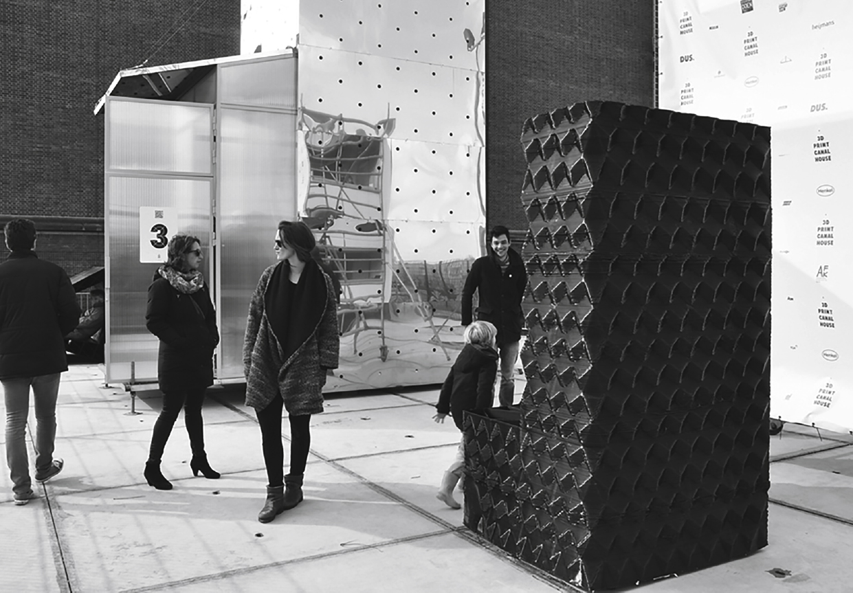
High tooling costs of the Multipoint method leads to exploration to lower cost procedures. Desktop 3D printers lower prices and their large format versions (BigRep) are a promising alternative for free-form architectural panel production. Recent developments such as KamerMaker (Fig. 13), a large size 3D printer by DUS Architects show the feasibility of plastic 3D printing building facade components, without the need of moulds (Fig. 14).
4Conclusions
Recent advances in digital processes allow for free-form architectural facade panel production at a reasonable price, by means of avoiding the use of moulds, which reduce significantly the associated costs, as in architecture none or little repetition is expected. Some of these digital processes, such as Multipoint one, have demonstrated the viability of free-form-no-mould architectural panel production. However, sophisticated tooling prices are still high and far from being widely accepted by the construction industry.
Nevertheless if the use of moulds is mandatory, digital additive, subtractive, and forming processes will allow obtaining complex free-form moulds at lower prices, without the use of craftsmanship, which reduce the cost of labour and as a result, the final budget.
The fast spreading of additive plastic based 3D desktop printers and the raising attempts to scale up these machines for architectural purposes, such as KamerMaker by DUS Architects, sets out new alternatives in no-mould low cost free-form architectural panels. These 3D Printing processes allow for free-form manufacturing panels, to show the bare material or to be finished on-site and off-site by adding one or more finishing coatings. Drawbacks in energy use and time consuming printing periods must be addressed. Material development plays a key role in realizing true functionality in parts produced, using Additive procedures. Reliability and commercial availability of these bigger printers are yet to be achieved.
Architects and small enterprises are leading this innovative path for 3D printing architectural components. It is yet to be proven that this will be a widely accepted method by the building industry or just another good idea that fails, due to the complex constraints involving the architectural product as a whole.
Notes
1 CAD, Computer-Aided-Design; CAM, Computer-Aided-Manufacturing.
Reference
1 | Alonso L, Bedoya C, Lauret B, Alonso F(2013) FTE: Sistema de cerramiento transparente, ligero, de altas prestaciones energéticas que permite el diseño con formas libres.nInformes de La Construcción532: 65443456doi: 0.3989/ic.12.068 |
2 | Alonso L, Lauret B, Castañeda E, Domínguez D, Ovando G(2014) Free-form architectural facade panels: An overview of available mass-production methods for free-form external envelopes2nd International Conference on Construction and Building Research2: 149156doi: 10.1007/978-94-007-7790-3_20 |
3 | Buswell RA, Soar RC, Pendlebury M, Gibb A, Edum-Fotwe F, Thorpe A(2005) Investigation of the potential for applying freeform processes to construction3rd International Conference on Innovation in Architecture, Engineering and Construction (AEC)Sariyildiz S, Tuncer BDelft University of TechnologyRotterdam141150 |
4 | Buswell RA, Soar RC, Gibb AGF, Thorpe A(2007) Freeform construction: Mega-scale rapid manufacturing for constructionAutomation in Construction16: 2224231doi: http://dx.doi.org/10.1016/j.autcon.2006.05.002 |
5 | Buswell RA, Thorpe A, Soar RC, Gibb AGF(2008) Design, data and process issues for mega-scale rapid manufacturing machines used for constructionAutomation in Construction17: 8923929doi: 10.1016/j.autcon.2008.03.001 |
6 | Hauschild M, Karzel R(2011) Digital processes. Planning, design, production. Detail PracticeMunich, GermanyBirkhäuser |
7 | Hopkinson N, Dickens P(2003) Analysis of rapid manufacturing using layer manufacturing processes for productionProceedings of the Institution of Mechanical Engineers. Part C: Journal of Mechanical Engineering Science27: 13139Special Issue on Rapid Manufacturing |
8 | Knaack U, Bilow M, Strauss H(2008) Rapids. Layered fabrication technologies for facades and building construction010Rotterdam, The Netherlands010 Publishers |
9 | Kolarevic B(2003) Architecture in the digital age: Design and ManufacturingNew York, NYTaylor & Francis Group |
10 | Kolarevic, B. (2005). Digital praxis: From digital to material. Proceedings of the 3rd Conference on Innovation in Architecture, Engineering and Construction (AEC), S. Sariyildiz & B. Tuncer (eds.), Delft University of Technology, Rotterdam, 1, 5-18. |
11 | Lee, G., & Kim, S. (2012). Case study of mass customization of double-curved metal facade panels using a new hybrid sheet metal processing technique. Journal of Construction Engineering and Management, 138, 1322-1330. doi: http://dx.doi.org/10.1061/(ASCE)CO.1943-7862.0000551 |
12 | Naboni R, Paoletti I(2015) Advanced Customization in Architectural Design and ConstructionSpringerBriefs in Applied Sciences and TechnologyMilan, ItalySpringer & Politecnico di Milano |
13 | Pegna J(1997) Exploratory investigation of solid freeform constructionAutomation in Construction5: 5427437doi: 10.1016/S0926-5805(96)00166-5 |
14 | Pronk, A., van Rooy, I., & Schinkel, P. (2010, January). Double-curved surfaces using a membrane mould. In: Symposium of the International Association for Shell and Spatial Structures (50th. 2009. Valencia). Evolution and Trends in Design, Analysis and Construction of Shell and Spatial Structures: Proceedings. Editorial Universitat Politècnica de València, 618-628. |
15 | Strauß, H. (2013). AM envelope. The potential of additive manufacturing for facade construction. Delft University of Technology: Architecture and the Built Environment. |
16 | Ver Bruggen, S. (2014, May 21). Chinese company prints 10 homes in one day. Retrieved from http://www.forumforthefuture.org/greenfutures/articles/chinese-company-prints-10-homes-one-day |
Figures and Tables
Fig.1
Railway Station, Innsbruck, made of glass panels (2007), Zaha Hadid.
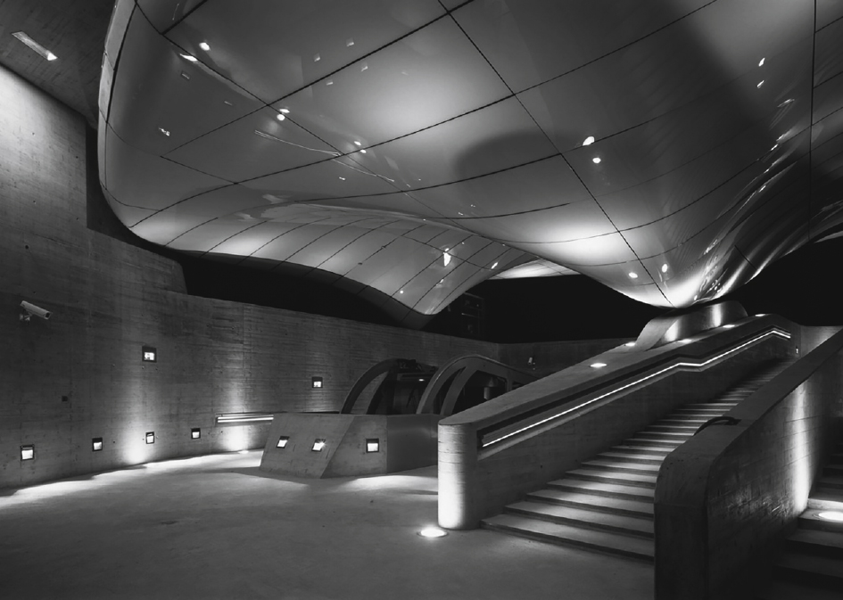
Fig.2
Styrofoam mould for polycarbonate panel of ‘The Bubble’, BMW Pavilion, Frankfurt (1999), Bernhard Franken.
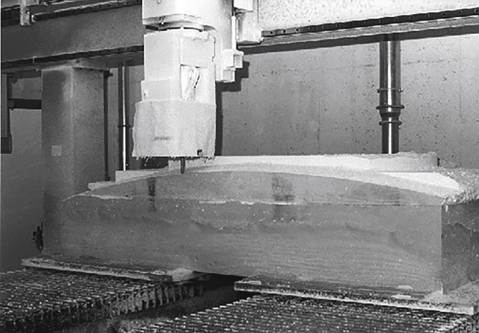
Fig.3
The reinforced concrete panels for Zollhof Tower, Düsseldorf (2000).
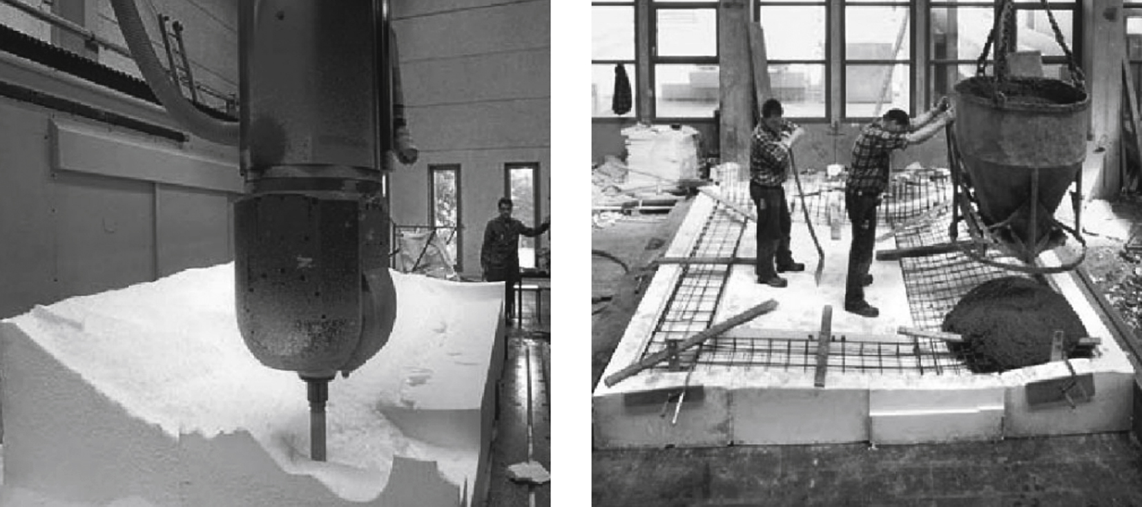
Fig.4
Moulds of polyestirene foam for Bus Station in Hoofddorp, the Netherlands (2003).
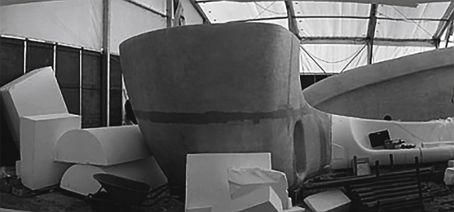
Fig.5
An example application of ISF: a 1/8 scale model of the front section of a Shinkansen (Bullet Train) made by Amino in Japan.
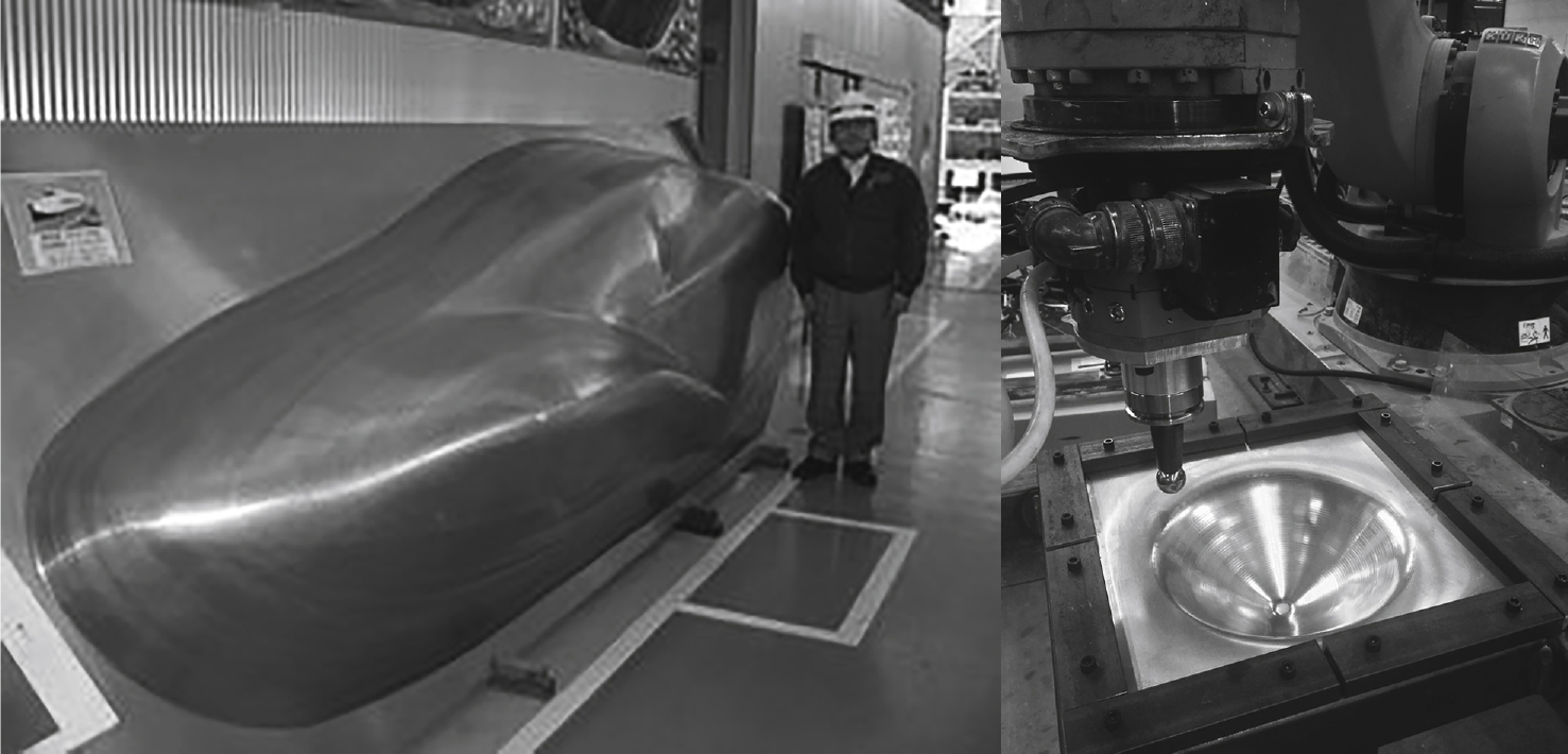
Fig.6
A multipoint forming (MPF) prototype unit was built at Jilin University in China.
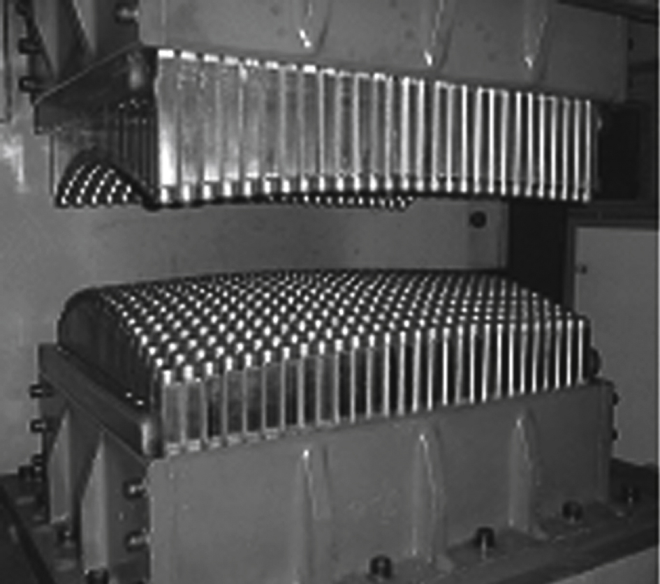
Fig.7
Printer BAAM (Big Area Additive Manufacturing).
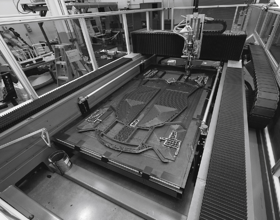
Fig.8
3D printed Shelby Cobra in 24 hours.
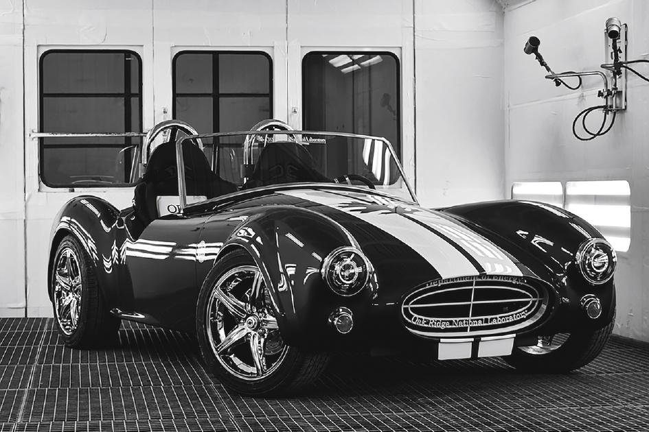
Fig.9
D-Shape machine. The machine uses sand mixed with an inorganic binder.
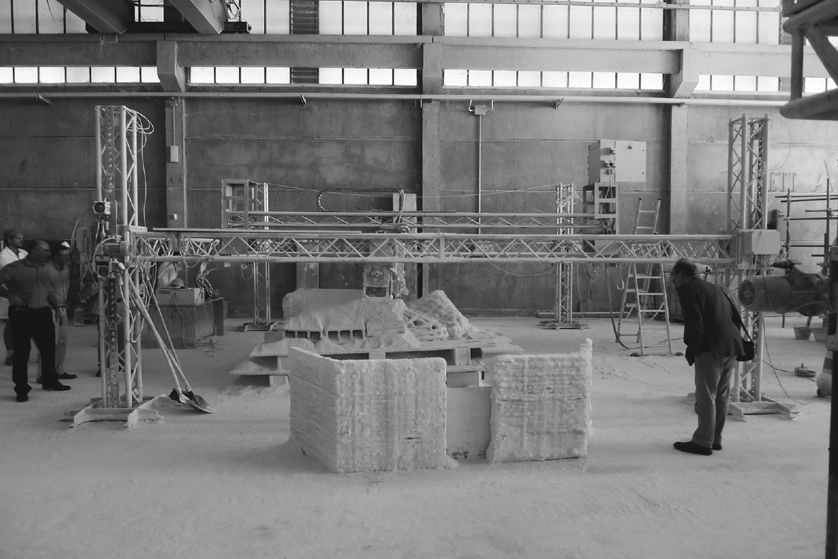
Fig.10
The Freeform Construction project’s proof of concept is a 1 × 1 m, one-tone reinforced concrete panel.
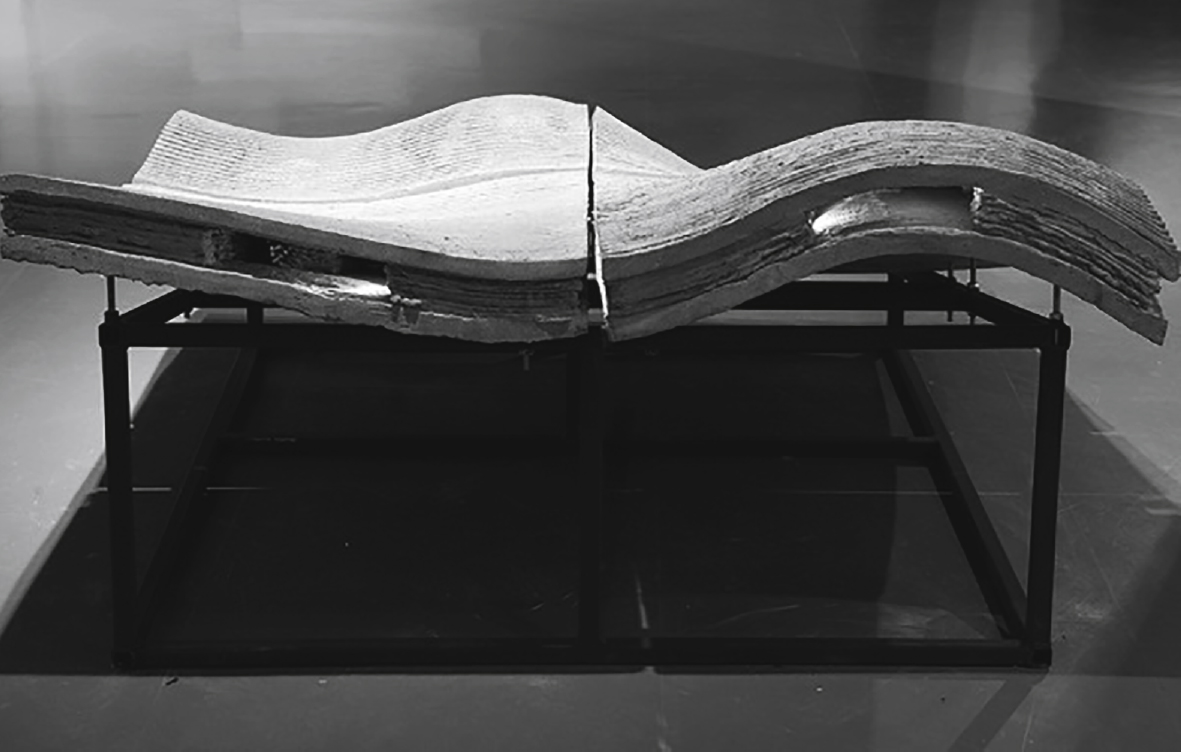
Fig.11
Multipoint stretch forming machine (photographs: courtesy of SteelLife).
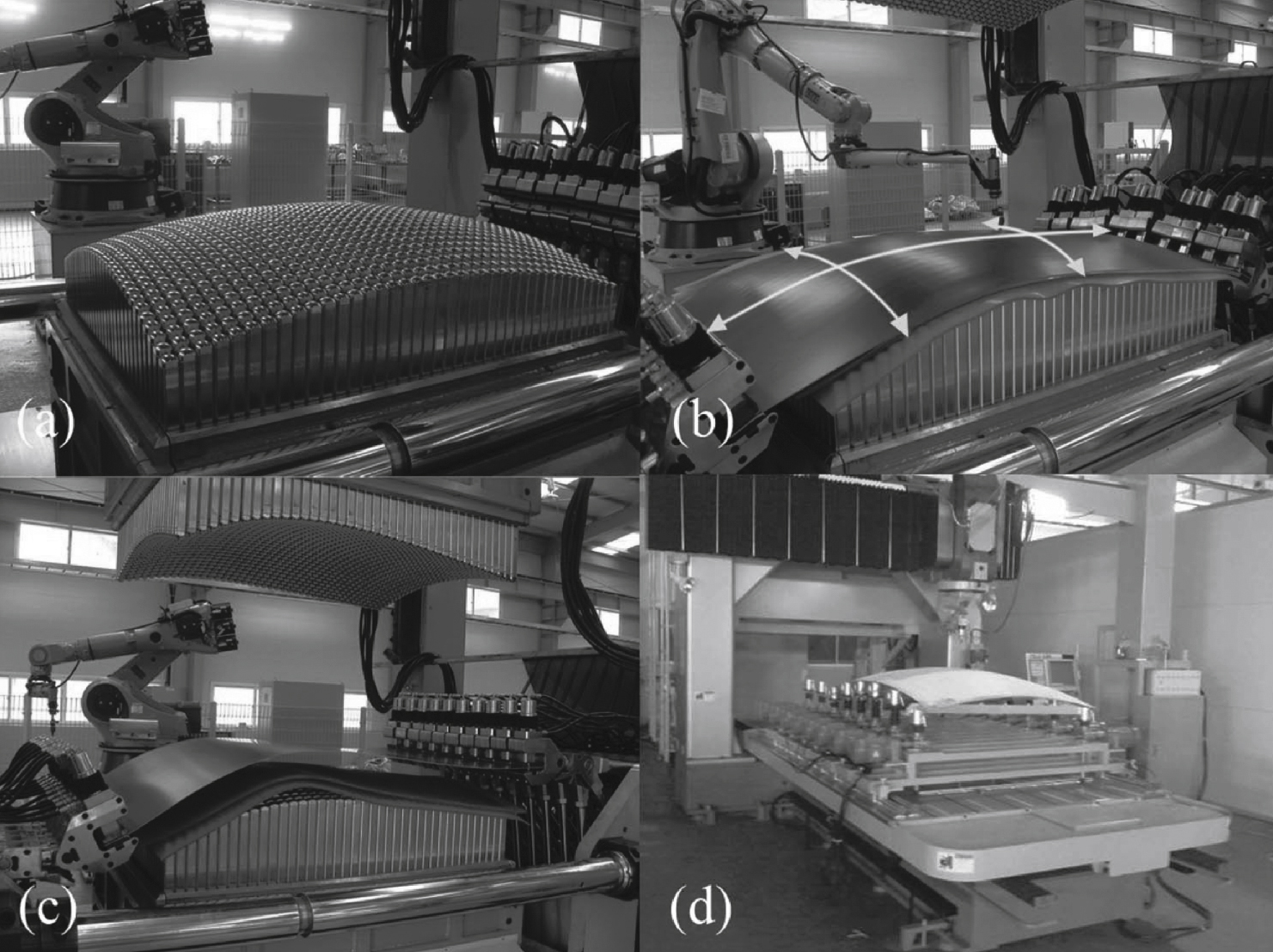
Fig.12
Free-form display 10 × 3 m at the Building Centre, London. Formtexx.
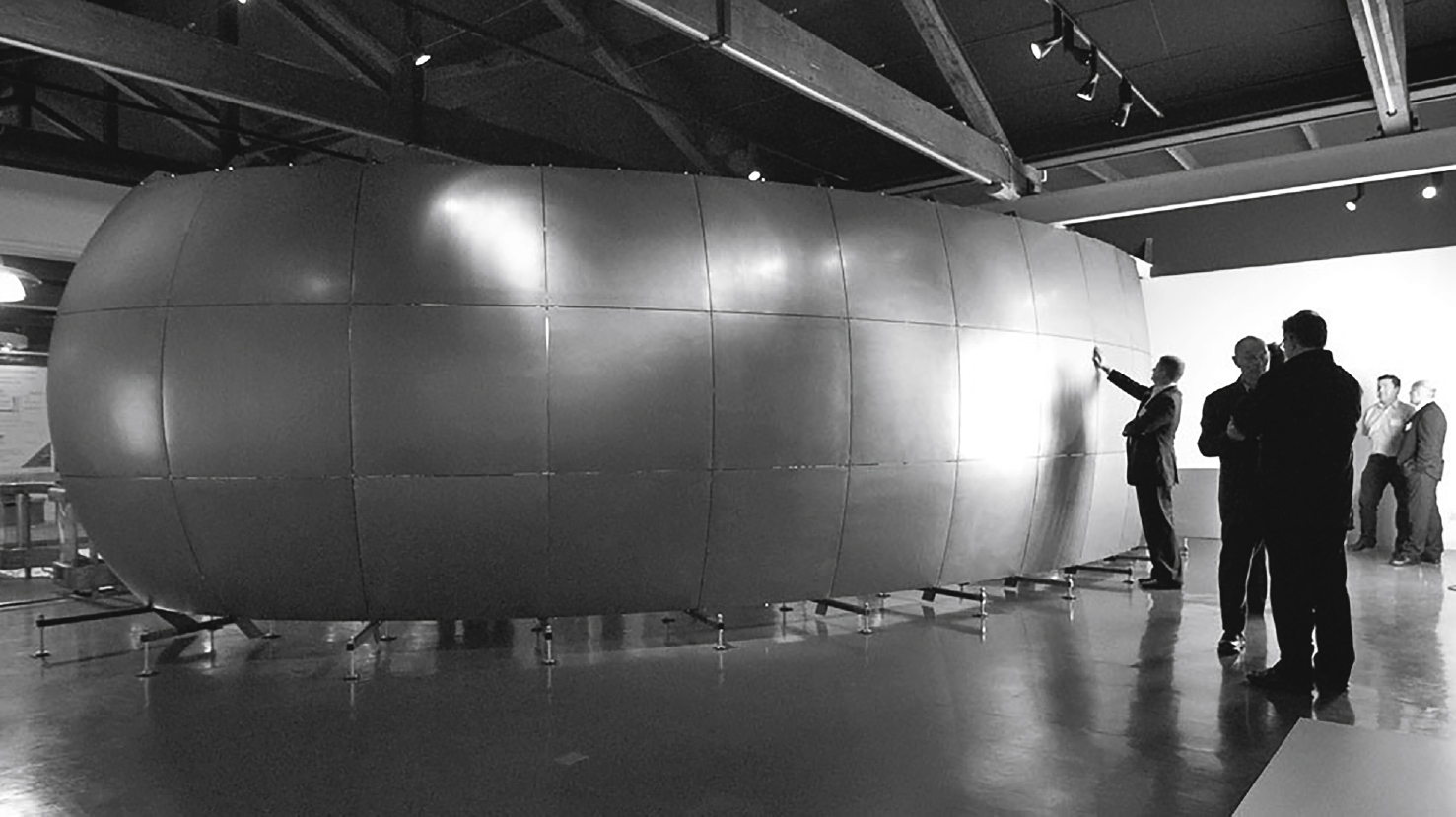
Fig.13
Kamermaker. Large 3D printer in a tuning shipping container.
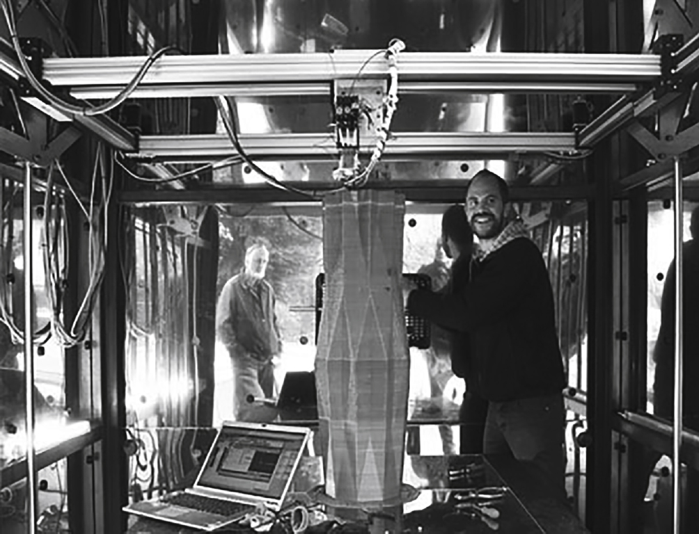
Fig.14
One of the pieces to the 3D Print Canal House.