
Novel stability approach using Routh-Hurwitz criterion for brain computer interface applications
Abstract
BACKGROUND:
The stability criterion approach is very important for estimating precise behavior before or after fabricating brain computer interface system applications.
OBJECTIVE:
A novel approach using the Routh-Hurwitz standard criterion method is proposed to easily determine and analyze the stability of brain computer interface system applications. Using this developed approach, we were able to easily test the stability of technical issue using simple programmed codes before or after brain computer interfaces fabrication applications.
METHODS:
Using a MATLAB simulation program package, we are able to provide two different special case examples such as a first zero element and a row of zeros to verify the capability of our proposed Routh-Hurwitz method.
RESULTS:
The MATLAB simulation program provided efficient Routh-Hurwitz standard criterion results by differentiating the highest coefficients of the
CONCLUSION:
This technical paper explains how to use our proposed new Routh-Hurwitz standard condition to simply ascertain and determine the brain computer interface system stability without customized commercial simulation tools.
1.Introduction
The importance of stability in a brain computer interface systems or applications is unquestionable because the neuro signals generated by human brain cannot be detected by unstable brain computer interface systems [1]. As a result, the impulse response of the output systems is infinite, although the brain computer interface system input is quite limited [2]. For instance, unstable brain computer interface systems often result in a certain amount of physical impairment or damage, that becomes pricy [3]. To better understand these brain computer interface systems, it is essential and indispensable to understand why the stability issue of the brain computer interface system matters so much and what is physically implemented in a MATLAB program software (MathWork Inc., Natik, MA, USA).
We are also able to consider the stability issues for other medical imaging systems or instruments such as X-ray, computed tomography, magnetic resonance imaging, and positron emission tomography modalities because the medical imaging systems must provide stable output signals to be processed all the time [1]. To design such a circuit in the medical systems, several parameters, such as power dissipation, input and output impedance matching, speed, voltage swing, supply voltage, bandwidth, linearity, noise level, and voltage gains, were measured to show the stability of the developed analog circuit [4]. The high voltage class-F power amplifier was properly designed to have a wide bandwidth and high voltage gain with stable S-parameters of input and output reflection coefficients for portable acoustic system applications [5].
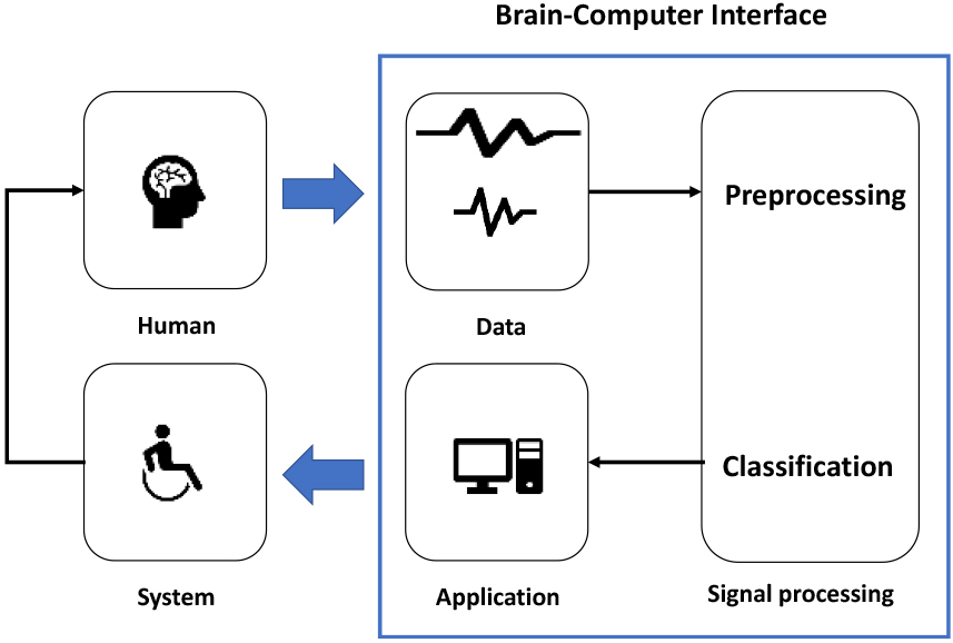
If any coefficients are zero values or below zero values, the designed engineering systems are in unbalanced conditions [6]. It is crucial to note, however, that even though all of the coefficients of the characteristic equation are positive, the proposed engineering system could be definitely in unstable conditions [7]. Figure 1 shows the fundamental stable signal processing diagram in the brain computer interfaces because of how stable systems in the brain computer interface applications are very important to process the obtained proper biomedical signals generated from the human brain [1]. As shown in the blue marked box, the brain computer interface system is a kind of black box so the system engineers or academic researchers typically do not know how to obtain and process the biomedical signals precisely without any simulation tool.
Figure 1.
A fundamental stable signal processing block diagram in brain computer interface systems.
Section 1 describes the fundamental concept of the brain computer interface system or application. Section 2 describes how to implement Routh-Hurwitz codes in the simulation tool. Section 3 describes the implemented results of the Routh-Hurwitz program codes using the MATLAB simulation tool. Section 4 is the conclusion of the paper.
2.Methods
The Routh-Hurwitz standard criterion method is composed of two major phases or steps [8]: First, we need to build up a data table called a Routh table. Second, we are able to examine the designed table to determine the pole numbers of such closed-loop systems placed in the imaginary axis, lef hand plane, or the right half plane [8]. Let
(1)
Equation (1) is simplified with a numerator equation
(2)
The Routh-Hurwitz standard condition focuses on the characteristic equation, which is the denominator polynomial
(3)
There are two rules for the
Therefore, on the one hand, if the
The empty field of the table indicates the ellipsis mark for repetitions. The number of elements in the table depends on the highest order of the brain computer interface differential equation. The order of the brain computer interface system is even so the end of the first row is non-zero. If the order of the brain computer interface system is odd, it is zero. Then,
(4)
The leftmost element is called the pivot element in the row. Therefore, in the row
where
(5)
3.Results and discussion
There are special or unusual cases related to the Routh-Hurwitz stability criteria [7], such as if the first term in any column row of the array is zero. In that case, we could avoid it by assuming an infinitely small value (
In brain computer interface systems, there are two types of transfer functions. One is an open-loop transfer function
If all the elements of any row in the array are supposed to be zero cases of the row of zeros, the system can be said to have symptoms of marginal stability. If we do not have a sign change in the new table using the supplementary equation, then it will indicate the given Routh system is stable. Problems related to the Routh-Hurwitz standard criterion method for stability of the brain computer interface system are explained with special cases for example numbers 2 and 3.
1. We assume a specific application system of the brain computer interface system using characteristic equations:
(6)
From Eq. (6), all the coefficients of the application systems are not zero, no sign changes and all of the coefficients in the systems are supposed to be positive. Thus, we then further proceed to build up the Routh array; in addition, we need to fill these wanted values.
From this calculated array above, certainly, all of the signs of the first column in the brain computer interface systems are not supposed to be negative and there are no sign variances, and as a result, there are no poles of the brain computer interface systems.
2. In special cases, when the first element in any column or array row is supposed to be zero, we examine the stability check of the given transfer function as follows:
(7)
From this problem, the characteristic equation is the denominator of
The sign changes occur in both instances, so it does not matter which one is chosen; both indicate that the brain computer interface system is not supposed to be stable with two poles in the right half plane. The resulting Routh array is as follows:
3. In special cases, when all elements of any row of the array are zero, i.e. row of zeros, we need to obtain the right half plane poles in the calculated function above.
(8)
As the
The row with all zeros or row of zeros in the Routh table is replaced with the coefficients obtained by differentiating the auxiliary equation to continue the calculation.
The solution of the linear differential equation or the poles of the transfer function in brain computer interface systems can be represented by the linear combination of the eigenvalues which are the poles or roots of the transfer function. Being stable means the poles or eigenvalues should reside in the left-half plane.
For higher-order linear brain computer interface systems, there are many poles in the transfer function [11]. By reducing dominant poles depending on customer requirement, we will obtain the lower order linear brain computer interface system and corresponding tangible transfer function which is applicable for stability analysis. Therefore, a simpler and standard transfer function could be derived.
Figure 2.
(a) MATALB program codes for giving input into simulation program, (b) step to calculate and give Routh array process, and (c) step to check sign changes for the result.
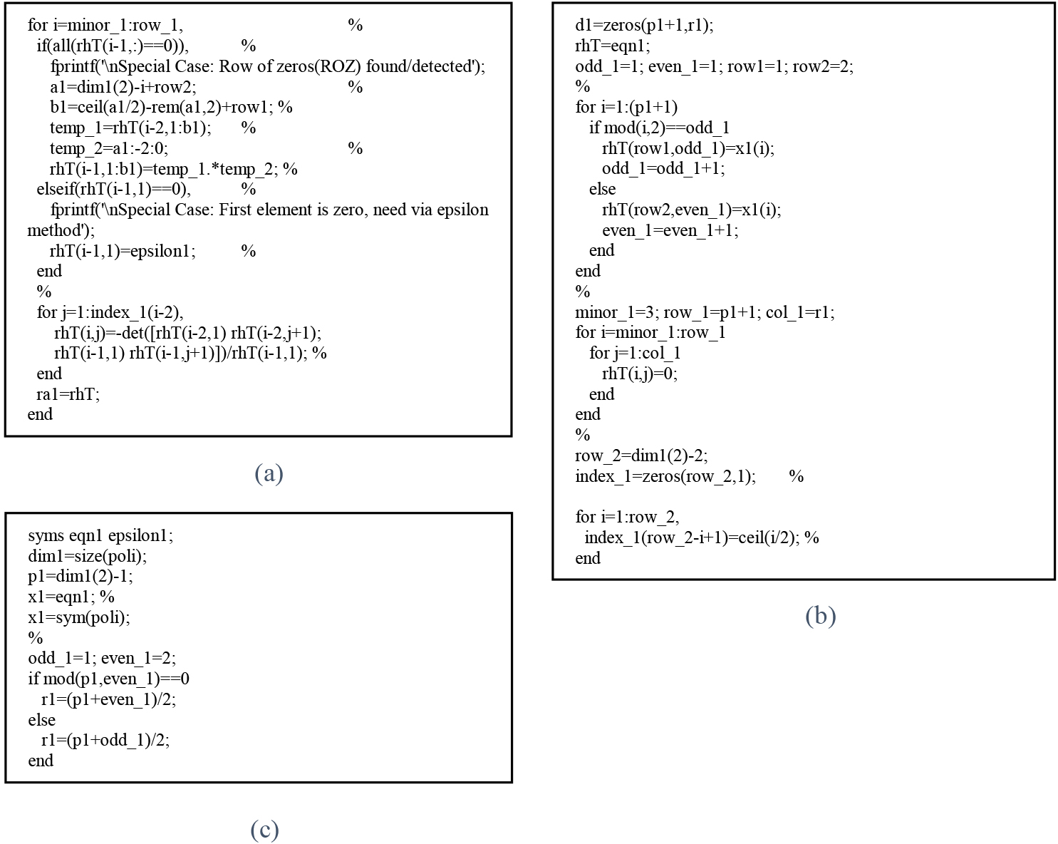
The following figures are part of the MATLAB programmed code used for creating the Routh table and providing a stable conclusion by inputting the highest
Figure 3.
Simulation results: giving input into the MATLAB simulation program for (a) the first column zero, and (b) row of zeros.
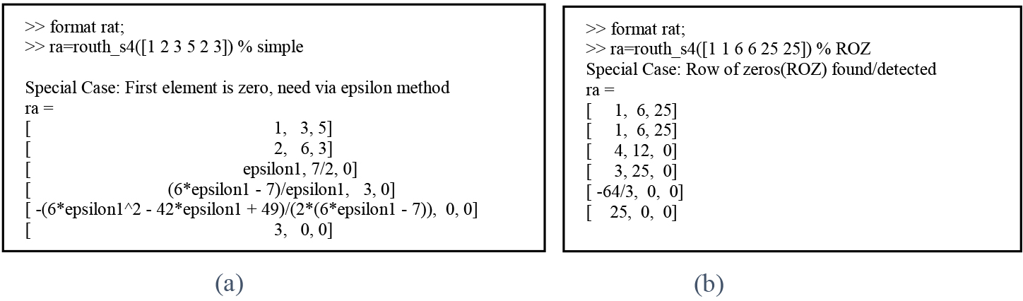
As mentioned above in the results section, we showed the procedures and examples of how to make the Routh-Hurwitz theory using the MATLAB software package. After analyzing the mathematical theory, we could run the example to effectively verify the newly proposed Routh-Hurwitz standard condition for brain computer interface systems.
In around 10–20 brain computer interface component systems, the input stage is the electrode on the scalp and the output stage is the filter for electrical waveforms or signals [12, 13]. The brain computer interface systems are a multidisciplinary field of technologies embracing biomedical, neuroscience, statistical signal processing, embedded systems, robotics, and artificial intelligence [14, 15, 16].
Here, we discussed and compared the results with previous studies related to the stability issues. In the early stages of research stages, when designing a new brain computer interface system or feasibility studies of a highly new scheme, the stability of a tentative system component is evaluated by a commercially available software stability program or a software approach such as MATLAB, OrCAD Pspice (Cadence Design System Inc., San Jose, CA, USA), Multisim (National Instruments Inc., Austin, TX, USA) and PSCAD (Manitoba Hydro International Ltd., Manitoba, Canada) to check the stability of the overall brain computer interface system applications [17, 18, 19]. In consequence, the developed simulation tool will much more attractive framework to check the overall stability of new brain computer interface hardware and software [20, 21, 22]. The digital X-ray-based system for medical purposes is very important to obtain stable patients’ images so the conventional Routh-Hurwitz standard criterion analysis provides stable information [23, 24]. The nonlinear system was analyzed with the fundamental Routh-Hurwitz theory to obtain stable system parameters [25, 26]. The current control system was used with basic Routh-Hurwitz standard criteria to determine the stability of the developed system [27, 28]. The common source or common gate power amplifiers with resistive or capacitive feedback circuits need to be analyzed with basic Routh-Hurwitz theory in the circuit level analysis with the S-parameter analysis tool [29, 30].
Compared with previous studies, our proposed novel Routh-Hurwitz standard criterion method could provide the stability issue with the eigenvalues of the characteristic equation in the transfer function. This equation could be implemented based on a simulation tool such as MATLAB program code, Simulink, or C programming code.
4.Conclusion
We propose a novel Routh-Hurwitz standard criterion method to provide stability information for brain computer interface systems or applications by observing the eigenvalues of the characteristic equation of a transfer function, which is the denominator polynomial of the function. For such brain computer interface systems or applications, precise and accurate voltage or current signal outputs are crucial because stability issues can result in physical injuries to humans or animals especially for brain computer interface systems or applications. Therefore, commercial simulation tools such as MATLAB or OrCAD Pspice programs utilizing simple and effective criteria to analyze and estimate stability issues need to be used in brain computer interface applications. However, such commercial simulation tools showed complex functions for newly designed medical systems such as digital X-ray or photoacoustic systems.
The characteristic equation or denominator polynomial must satisfy the Routh-Hurwitz polynomial to stabilize the brain computer interface system applications. There are two special cases in our proposed Routh-Hurwitz standard criterion calculation. The first case is when the at least first term in any row of the column is supposed to be zero, and the second one is when all the elements of any row in the array are supposed to be zero. The simulation program could generate a new Routh-Hurwitz standard criterion output result by providing desired inputs of the highest power of
Conflict of interest
None to report.
Funding
This work was supported by the Korea Institute for Advancement of Technology (KIAT) grant funded by the Korean Government (MOTIE) (P0011930, The Establishment Project of Industry-University Fusion District). This work was supported by the National Research Foundation of Korea (NRF) grant funded by the Korea government (MSIT) (No. 2020R1A2C4001606).
References
[1] | Tan D, Nijholt A. Brain-computer Interfaces and Human-computer Interaction. New York, NJ, USA: Springer; (2010) . |
[2] | Dass H. Advanced Engineering Mathematics. New Delhi, India: S. Chand Publishing; (2008) . |
[3] | Saltzman WM. Biomedical Engineering: Bridging Medicine and Technology. Cambridge, United Kingdom: Cambridge University Press; (2009) . |
[4] | Jung U, Choi H. Active echo signals and image optimization techniques via software filter correction of ultrasound system. Applied Acoustics. (2022) ; 188: : 108519. doi: 10.1016/j.apacoust.2021.108519. |
[5] | Kim K, Choi H. High-efficiency high-voltage class F amplifier for high-frequency wireless ultrasound systems. PLOS ONE. (2021) ; 16: (3): e0249034. doi: 10.1371/journal.pone.0249034. |
[6] | Stroud KA, Booth DJ. Engineering Mathematics. London, United Kingdom: Macmillan International Higher Education; (2013) . |
[7] | Ho M-T, Datta A, Bhattacharyya SP. An elementary derivation of the Routh-Hurwitz criterion. IEEE Trans Autom Control. (1998) ; 43: (3): 405-9. doi: 10.1109/9.661607. |
[8] | Trentelman HL, Stoorvogel AA, Hautus M. Control Theory for Linear Systems. Berlin, Germany: Springer Science & Business Media; (2012) . |
[9] | Dorf RC, Bishop RH. Modern control systems. New Jersey, NY, USA: Pearson Prentice Hall; (2008) . |
[10] | Yang WL, Kim B. Eigenface analysis for brain signal classification: A novel algorithm. Int J Telemed Clin Pract. (2017) ; 2: (2): 148-53. doi: 10.1504/IJTMCP.2017.083887. |
[11] | Schalk G, Mellinger J. A practical guide to brain-computer interfacing with BCI2000: General-purpose software for brain-computer interface research, data acquisition, stimulus presentation, and brain monitoring. Berlin, Germany: Springer Science & Business Media; (2010) . |
[12] | Khademi S, Neghabi M, Farahi M, Shirzadi M, Marateb HR. A comprehensive review of the movement imaginary brain-computer interface methods: Challenges and future directions. Artificial Intelligence-Based Brain-Computer Interface. (2022) ; 2022: : 23-74. doi: 10.1016/B978-0-323-91197-9.00004-7. |
[13] | Saha S, Mamun KA, Ahmed K, Mostafa R, Naik GR, Darvishi S, et al. Progress in Brain Computer Interface: Challenges and Opportunities. Frontiers in Systems Neuroscience. (2021) ; 15. |
[14] | Mridha MF, Das SC, Kabir MM, Lima AA, Islam MR, Watanobe Y. Brain-computer interface: Advancement and challenges. Sensors. (2021) ; 21: (17): 5746. doi: 10.3389/fnsys.2021.578875. |
[15] | Bobrov P, Frolov A, Cantor C, Fedulova I, Bakhnyan M, Zhavoronkov A. Brain-computer interface based on generation of visual images. PLoS One. (2011) ; 6: (6). doi: 10.1371/journal.pone.0020674. |
[16] | Chin-Teng L, Bor-Shyh L, Fu-Chang L, Che-Jui C. Brain Computer Interface-Based Smart Living Environmental Auto-Adjustment Control System in UPnP Home Networking. IEEE Syst J. (2014) ; 8: (2): 363-70. doi: 10.1109/JSYST.2012.2192756. |
[17] | Nam CS, Nijholt A, Lotte F. Brain-computer interfaces handbook: technological and theoretical advances. Boca Raton, FL, USA: CRC Press; (2018) . |
[18] | Pfurtscheller G, Neuper C, Guger C, Harkam W, Ramoser H, Schlogl A, et al. Current trends in Graz brain-computer interface (BCI) research. IEEE Trans Neural Syst Rehabil Eng. (2000) ; 8: (2): 216-9. doi: 10.1109/JSYST.2012.2192756. |
[19] | Wolpaw JR, Birbaumer N, Heetderks WJ, McFarland DJ, Peckham PH, Schalk G, et al. Brain-computer interface technology: A review of the first international meeting. IEEE Trans Neural Syst Rehabil Eng. (2000) ; 8: (2): 164-73. doi: 10.1109/tre.2000.847807. |
[20] | Vidaurre C, Krämer N, Blankertz B, Schlögl A. Time Domain Parameters as a feature for EEG-based Brain-Computer Interfaces. Neural Networks. (2009) ; 22: (9): 1313-9. doi: 10.1016/j.neunet.2009.07.020. |
[21] | Jinyi L, Yuanqing L, Hongtao W, Tianyou Y, Jiahui P, Feng L. A hybrid brain computer interface to control the direction and speed of a simulated or real wheelchair. IEEE Trans Neural Syst Rehabil Eng. (2012) ; 20: (5): 720-9. doi: 10.1109/TNSRE.2012.2197221. |
[22] | Ilyas M, Saad P, Ahmad M, Ghani A. Classification of EEG signals for brain-computer interface applications: Performance comparison. 2016 International Conference on Robotics, Automation and Sciences (ICORAS), Melaka, Malaysia. (2016) . doi: 10.1109/ICORAS.2016.7872610. |
[23] | Prince JL, Links JM. Medical Imaging Signals and Systems. Upper Saddle River, NJ, USA: Pearson Prentice Hall. (2006) . |
[24] | Stacy RW. Essentials of Biological and Medical Physics. New York, NJ, USA: McGraw-Hill; (1955) . |
[25] | Isidori A. Nonlinear Control System. New York, NJ, USA: Springer; (1995) . |
[26] | Irwin JD, Nelms RM. Basic engineering circuit analysis. Hoboken, NJ, USA: John Wiley & Sons; (2020) . |
[27] | Bateson RN. Introduction to Control System Technology. Upper Saddle River, NJ, USA: Prentice Hall; (1989) . |
[28] | Sastry S. Nonlinear System: Analysis, Stability, and Control. Berlin, Germany: Springer; (1999) . |
[29] | Allen PE, Holberg DR. CMOS Analog Circuit Design. Oxford, United Kingdom: Oxford University Press; (2002) . |
[30] | Kang S-M, Leblebici Y. CMOS Digital Integrated Circuits. New York, NJ, USA: McGraw-Hill Education; (2003) . |


