
Preliminary development and technical evaluation of a belt-actuated robotic rehabilitation platform
Abstract
BACKGROUND:
To provide effective rehabilitation in the early post-injury stage, a novel robotic rehabilitation platform is proposed, which provides full-body arm-leg rehabilitation via belt actuation to severely disabled patients who are restricted to bed rest.
OBJECTIVE:
To design and technically evaluate the preliminary development of the rehabilitation platform, with focus on the generation of various leg movements.
METHODS:
Two computer models were developed by importing the components from SolidWorks into Simscape Multibody in MATLAB. This allowed simulation of various stepping movements in supine-lying and side-lying positions. Two belt-actuated test rigs were manufactured and automatic control programs were developed in TIA Portal. Finally, the functionality of the test rigs was technically evaluated.
RESULTS:
Computer simulation yielded target positions for the generation of various stepping movements in the experimental platforms. The control system enabled the two-drive test rig to provide three modes of stepping in a supine position. In addition, the four-drive test rig produced walking-like stepping in a side-lying position.
CONCLUSIONS:
This work confirmed the feasibility of the mechanical development and control system of the test rigs, which are deemed applicable for further development of the overall novel robotic rehabilitation platform.
1.Introduction
According to the report from the World Health Organization on disability, 15% of the world population suffers from some kind of disability, of which 2 to 4% experience significant functional difficulties [1]. Therefore, effective rehabilitation technology is required to restore the functional activities of daily living. Among the current rehabilitation programmes, robot-assisted training is considered as a promising paradigm, especially for patients with severe impairment levels [2].
There are many rehabilitation robotic systems available on the market. Robots for gait training encompass exoskeleton-based systems (e.g. Lokomat, Hocoma AG, Switzerland) and end-effector systems (e.g. G-EO System, Reha Technology AG, Switzerland; Gait Trainer, Reha-Stim GmbH, Germany). They provide gait training on a stationary base (e.g. Lokohelp Pedago, Lokohelp Group, Germany) or mobile walking on the ground (e.g. Andago, Hocoma AG, Switzerland) [3]. For robot-assisted therapy of the upper limbs, the Armeo product series (Hocoma AG) provides various therapies in the shoulder, elbow, wrist and fingers. Clinical studies have confirmed the benefits of robot-assisted training for upper-limb [4] and lower-limb rehabilitation [5].
Despite availability of many rehabilitation robotic systems, there is large potential for mechanical and functional improvement. Current rehabilitation robots on the market provide therapy only for the lower limbs or for the upper limbs, but there is no system that can produce coordinated arm-leg training. Recent neurophysiological research revealed “interlimb neural coupling” during walking [6] and proposed that synchronised arm and leg movement should be practised to promote neural plasticity [7]. Arm movement in addition to leg activity is considered as a promising rehabilitation paradigm [8]. Furthermore, recent research revealed the advantages of cable-driven robotic devices. Due to characteristics such as low inertia, easy configuration and high speed and power output, belt actuation is applied in robotic arm rehabilitation [9, 10] and gait restoration [11, 12]. Such soft interfaces with the human removes the motion constraints brought by conventional rigid exoskeletons. Belt actuation can produce natural compliance in movement control [13]. Therefore, belt actuation is considered promising to provide comfortable and compliant human-robot interaction. Lastly, it is generally believed to be important to start training as soon as possible [14, 15, 16, 17]. However, few robotic systems exist for early rehabilitation of arm-leg movement.
Based on the limitations of current rehabilitation products, a novel belt-actuated robotic rehabilitation platform is proposed here to provide full body rehabilitation to severely disabled patients who are restricted to bed rest. The principal system feature is to use belts to transfer the drive power to produce constraint-free movement. The platform aims to provide various types of exercise for the arms and legs, with the following functional requirements:
(i) to provide various arm-leg movements in a supine-lying position: ipsilateral/bilateral shoulder, elbow, hip and knee flexion, and a combination of arm and leg flexion movement;
(ii) to provide synchronous arm-leg walking-like movement in a side-lying position: ipsilateral shoulder, elbow, hip and knee flexion, ipsilateral shoulder and hip extension, and ipsilateral walking-like movement;
(iii) to provide various arm-leg movements in the medial-lateral plane: apart from movement in the sagittal plane described above, shoulder and hip abduction/adduction should be provided.
Requirements (i) and (iii) provide training of various movements that are normally used in daily life, such as shoulder and hip flexion, abduction and adduction. Hip extension is important for activation of the leg muscles during walking, and is considered as a key factor for walking rehabilitation [18, 19, 20]. As supine lying on a bed prevents the hip and shoulder joints from extension, walking-like stepping with arm movement is to be produced in a side-lying position, as described in (ii).
To meet all of these functional requirements, the overall platform will have substantial complexity in terms of design and control algorithms. Therefore, development of this novel system started with the generation of leg movement, as described in the present work, while arm movement will be implemented in the future. The aim of this work was to design and technically evaluate the preliminary development of the rehabilitation platform, with focus on the generation of various leg movements. This work describes kinematic analysis, mechanical design, control development and experimental evaluation of two test rigs for generation of various stepping movements in a supine-lying position and walking-like stepping in a side-lying position.
2.Methods
The kinematics of various stepping movements were analysed using computer simulation. The mechanical concept of two test rigs was designed using CAD (SolidWorks, Version 2018, Solid Solutions AG, Zürich, Switzerland). After the belt-actuated test rigs were manufactured and assembled with control hardware (Siemens Switzerland Ltd., Zürich), the control programs were developed in TIA Portal (V15.1, Siemens Switzerland Ltd.) and finally the functionality of the test rigs was technically evaluated.
2.1Computer simulation
Two simulation models (Fig. 1a and b) were developed by importing the components from SolidWorks into Simscape Multibody in MATLAB (Version 2018a, the MathWorks GmbH, Bern, Switzerland). A fixed step solver method (ODE3, Bogacki-Shampine) [21] with a step size of 0.01 s was used to simulate stepping in supine and side-lying positions.
Figure 1.
Model development for simulation of stepping in supine-lying (a, c) and side-lying (b, d) positions.
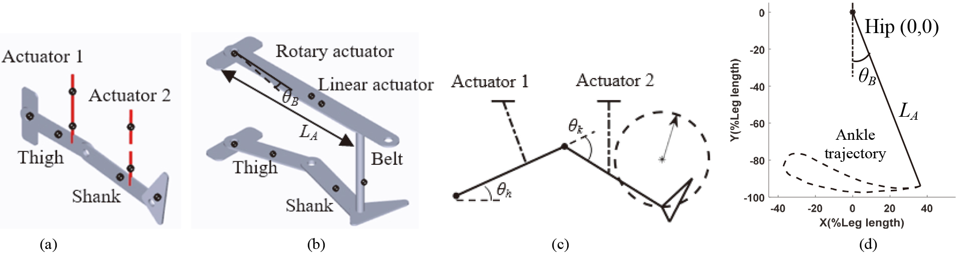
The model of supine-lying stepping (Fig. 1a) included two linear actuators and a leg frame, which represents two belts pulling the thigh and shank segments. The parameters such as segmental length, centre of mass and moment of inertia were defined using anthropometric data from the literature [22]. This model simulated two types of physiologically feasible movement: (i) two-position training, where the range of motion for the hip and knee joints was defined by specifying two joint positions; and (ii) end-effector training, where a random circular foot trajectory was defined by specifying the centre and radius of a circle (Fig. 1c).
The model of side-lying stepping (Fig. 1b) included a leg frame and a length-adjustable support bar swaying upon a pivot which was above the hip joint. The other end of this swaying bar was attached to the ankle segment via a belt. One actuator rotates the support bar
(1)
(2)
where
2.2Mechanical development
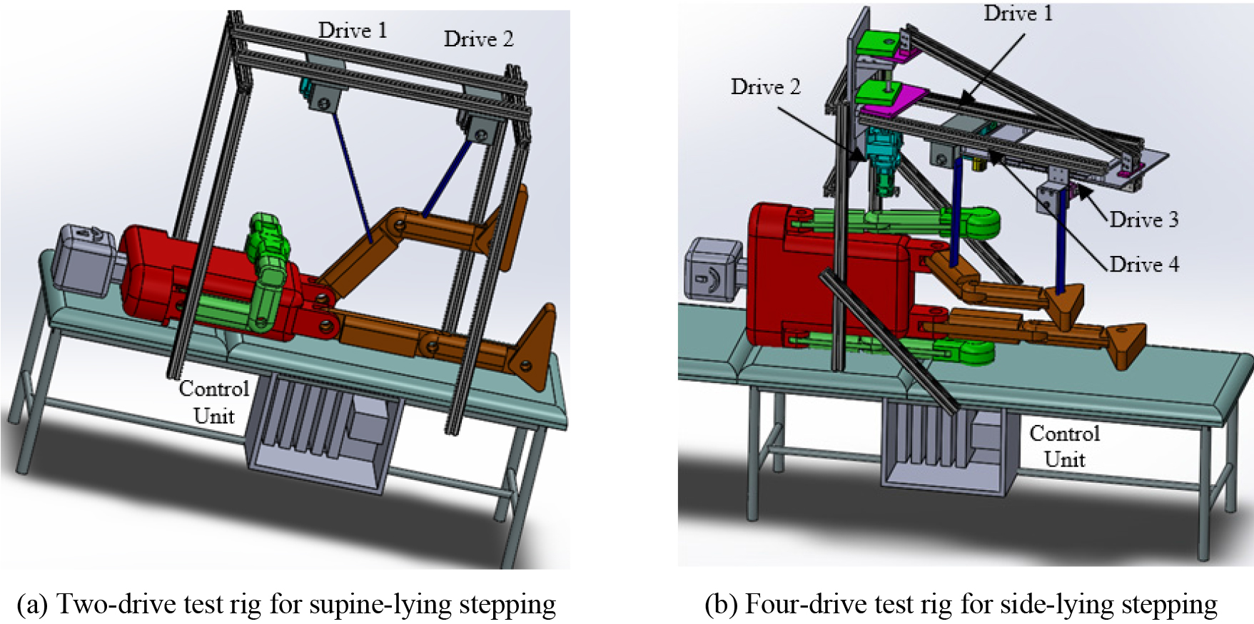
Two test rigs (Fig. 2) were designed to be fixed on a bed: a two-drive test rig for supine stepping, and a four-drive test rig for walking-like stepping in a side-lying position. The test rig for supine-lying stepping (Fig. 2a) used Drives 1 and 2 to pull the thigh and shank via belts. The test rig for side-lying stepping (Fig. 2b) included a rotatable support frame and four drives. Drive 2 actuated the support frame to sway upon a pivot in the horizontal plane, i.e. to control
Figure 2.
Mechanical concept of the belt-actuated test rigs.
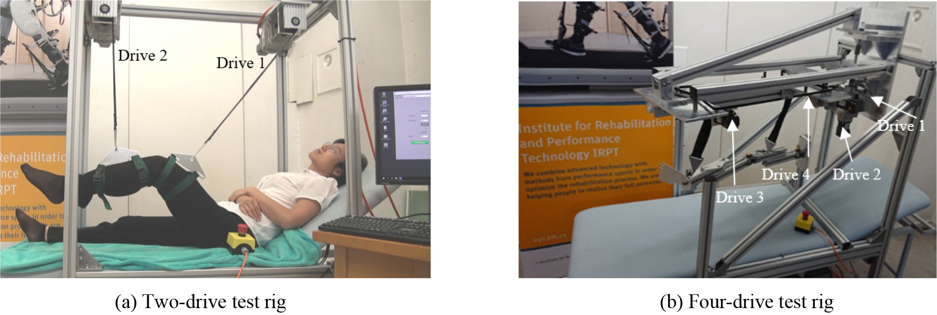
In order to test the feasibility of mechanical concept, two test rigs were manufactured (Fig. 3) and assembled with control hardware (Siemens Switzerland Ltd., Zurich). Drive 1 was a combination of a servo motor (1FK2103, 200 W) and a gearbox (2KJ3201, ratio
Figure 3.
Two belt-actuated test rigs.
2.3Control system
To evaluate the automatic control systems, different stepping movements were implemented in the test rigs. The control task was mainly to send the position and speed commands to each drive so as to produce the required leg movement. The control algorithms were programmed using Structured Control Language in TIA-Portal, and were downloaded to the IPC. The function blocks MC_MoveRelative and MC_MoveVelocity were used, which enabled the motor to move according to the reference position and speed profiles. The reference positions and speeds were defined via a human machine interface (HMI) window.
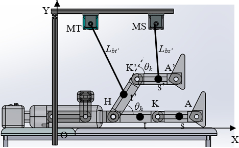
The HMI program provided automatic calibration. As shown in Fig. 4, the reference frame was the two-drive test rig, where Point O is the centre (0, 0), and Points MT and MS are the positions for the thigh and shank motors. Points t and s are the belt attachment positions for the thigh and shank. After the user lay straight in a supine position on the bed, the body segment positions including the hip (H), knee (K) and ankle (A) joints, as well as the belt attachment points t and s were measured and entered in the HMI page. The thigh and shank were considered as cylinders with the same diameter. The thigh and shank lengths
(3)
(4)
After calibration, the software for three training modes was implemented using the algorithms described in the following in TIA Portal and downloaded to the IPC. The required position and speed commands for each motor were obtained, thereby producing the target movement.
Figure 4.
Human machine interface in the control program.
2.3.1Two-position training
In this mode, the range of motion for the hip and knee joints was defined by specifying the minimal and maximal joint angles. Then the software calculated the motor positions and speeds to achieve the target movement synchronously.
For a leg position with random hip and knee angles
(5)
where
(6)
(7)
The belt length from the motor MS to the new shank position,
(8)
where
(9)
(10)
Thus, for any hip and knee angles
2.3.2End-effector training
In this mode, the user determined an arbitrary circular foot trajectory by defining the centre and radius of a circle. Suppose the ankle segment is used to represent the foot trajectory. For the defined ankle position (
(11)
The angle between
(12)
The hip and knee angles
(13)
(14)
Implementing Eqs (3)–(4) and (11)–(14) in end-effector mode, the corresponding hip and knee angles were calculated for any defined ankle position. Then using Eqs (5)–(10), the belt lengths
2.3.3Teach-replay training
In this mode, the experimenter firstly guided the leg movement manually, and then the test rig replayed this taught movement repetitively. This functionality was achieved via three steps: torque-tuning phase, teaching phase, and replay phase.
The torque-tuning phase mainly searched for the required torque when each motor rotated at different speeds. In this step, the motor was set in speed mode, and different speeds were implemented. Then the torques at these speeds, which mainly compensated the system friction, were recorded. Mathematical fit functions were estimated to approximate the torque curves with speeds for both motors. These functions for friction compensation were implemented in TIA Portal. Furthermore, the additional torques to move the user’s thigh and shank were implemented in the algorithms. The combined torques for friction compensation and leg gravity compensation defined the required torque to produce the specific movement.
In the teaching phase, the experimenter moved the user’s leg. The program compared the difference between the actual and required torques. The speed commands to each motor were then set proportional to the torque difference. During this phase, the actual motor positions were also recorded.
Lastly, in the replay phase, the motors were set in position mode, and repeated the motor trajectories that were recorded in the teaching phase.
2.3.4Walking-like stepping
To achieve this functionality, the same positions for Drives 2 and 4 as those obtained from simulation (Section 2.1) were implemented as the target performance in TIA Portal. The belts that pulled the side-lying leg should be in tension so that the ankle segment can follow the movement produced by the support frame. Therefore, in the program, Drives 1 and 3 were set to pull the leg with a fixed torque limit.
3.Results
Simulation and experimental evaluation results of various stepping movements in supine-lying and side-lying positions are presented in this section. The belt length and displacement were normalised to the leg length.
3.1Computer simulation
Kinematic simulation yielded target position profiles for movement control. The belts pulled the thigh and shank upward by 17% and 43% of leg length, respectively, so as to produce flexion of 60
Figure 5.
The simulated belt lengths for (a) two-position training and (b) end-effector circular training.
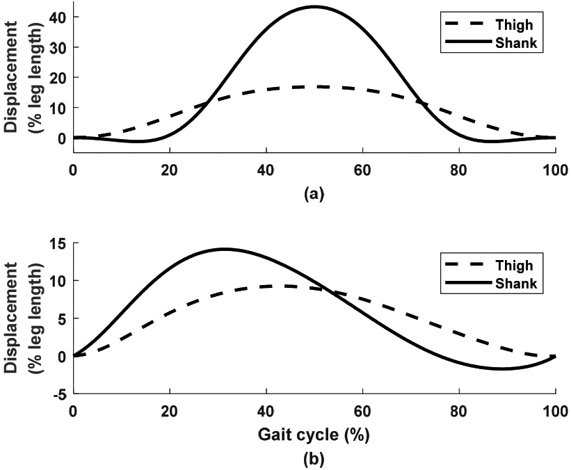
Figure 6.
The simulated (a) bar length
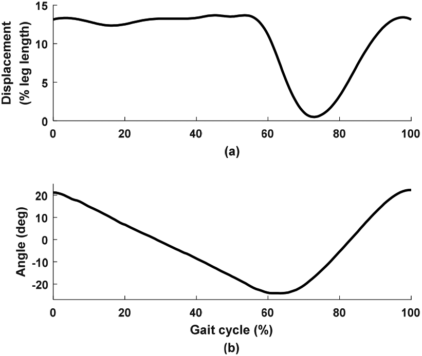
To produce walking-like ankle movement, the support bar should sway between
3.2Functional evaluation
A test person with a thigh length of 0.35 m and a shank length of 0.37 m lay on the bed with the two-drive test rig, with hip and knee angles
Figure 7.
End-effector circular stepping in a supine position. (a) Hip joint; (b) knee joint; and (c) foot trajectory. Dashed lines: simulation, solid lines: experiment.
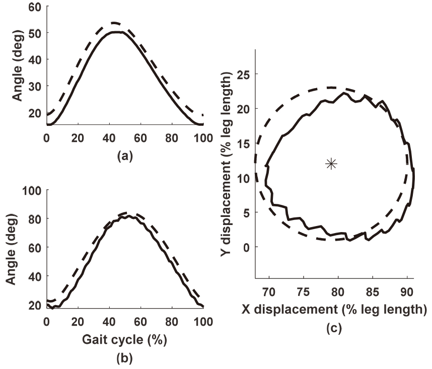
Figure 8.
The required torques from the two motors to compensate friction in the two-drive test rig. Exp: experiment.
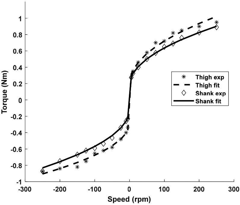
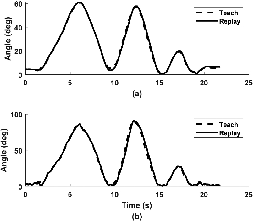
Figure 9.
The experimental performance of stepping in teach-replay training. (a) Hip joint; and (b) knee joint.
The teach-replay function required friction compensation. The torque-tuning phase yielded the required torque curves at different speeds, which were nonlinear and different when the motors changed direction. The thigh motor required slightly larger torque (stars in Fig. 8) than the shank motor (diamonds in Fig. 8) to compensate friction. The fit functions (dashed and solid lines in Fig. 8) for the torque curves
(15)
(16)
(17)
(18)
In the teaching phase (see the attached video “Experiment. mp4”: Part One “Teach-replay training”), the experimenter manually moved the leg of the test person in random trajectories (dashed lines in Fig. 9). In the replay phase, similar joint trajectories were produced (solid lines in Fig. 9).
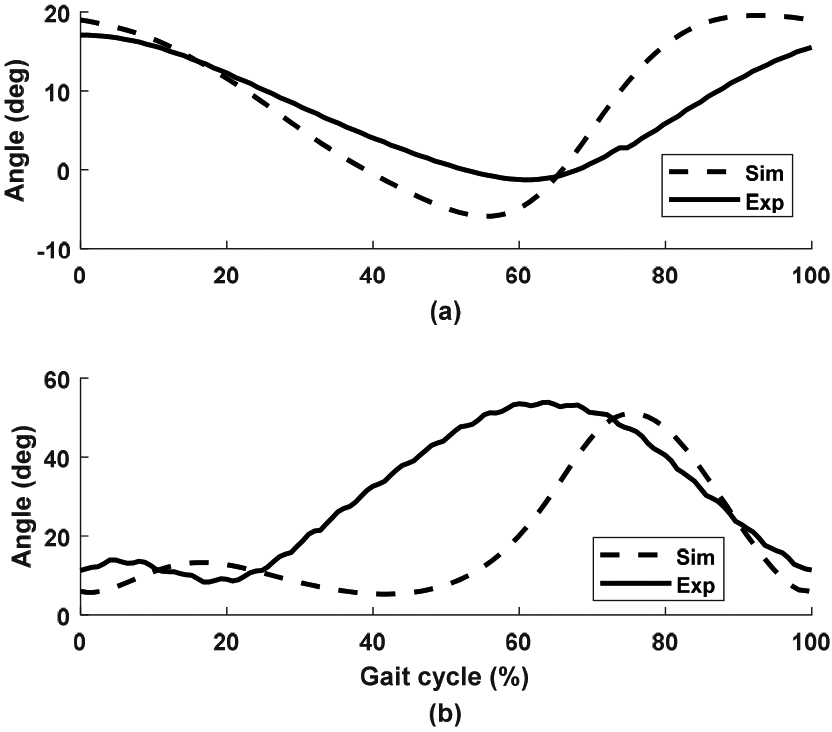
In the four-drive test rig, the control signals in Fig. 6 were implemented, and synchronous stepping movement was produced in the leg frame (see the attached video “Experiment. mp4”: Part Two). The hip extended, albeit with a limited range (Fig. 10a). This was because the hip joint had larger friction than the knee joint in the leg frame. Therefore, the knee joint flexed more while the hip extended less. Due to belt deformation, the knee joint flexed, but not as quickly as the movement shown in simulation (Fig. 10b). Belt flexibility also caused small ripples in the knee joint trajectory. Nevertheless, the test rig produced walking-like stepping with synchronised hip and knee movement.
Figure 10.
The performance of stepping in a side-lying position. (a) Hip joint; and (b) knee joint. Sim: simulation; Exp: experiment.
4.Discussion
The aim of this work was to design and technically evaluate the preliminary development of the rehabilitation platform, with focus on the generation of various leg movements. This work described kinematic analysis, mechanical design, control development and experimental evaluation of two test rigs for generation of various stepping movements in a supine-lying position and walking-like stepping in a side-lying position. The feasibility of the innovative mechanical configuration and automatic control systems to produce various leg movements was investigated. Although only leg movements were implemented in this study, the automatic control system and mechanical configuration provided useful information for development of the overall robotic arm-leg rehabilitation platform.
The simulation study yielded feasible kinematic solutions for the proposed overall platform, which is a sophisticated multi-functional system. Due to its compliance properties, belt actuation was selected for the proposed platform. However, belt control and mechanical development to achieve such functions were difficult tasks. The kinematic simulation provided an effective approach. With focus on the leg movement, two simulation models yielded the technical specifications of the drives, and the mechanical configuration for the generation of various stepping movements. The approach of importing the SolidWorks components into Simulink models provided vivid mechanical animation, which effectively guided the initial concept development of the belt-actuated test rigs.
The two-drive test rig produced three useful training modes, which validated the feasibility of using automatic hardware and software for real-time movement control. Programming in TIA Portal and implementing via the IPC, this test rig produced the target motor positions and speeds to achieve the required flexion movement. Two-position and end-effector training modes are often-used rehabilitation therapies. The functional highlight of the current two-drive rig was the teach-replay training, which allowed the operator to define any physiological leg flexion movement by manual guidance. This training mode is considered useful in the potential clinical setting where therapists could prescribe the patient-specific movement patterns by manipulation. This test rig achieved the target leg flexion movement in the functional requirement list, part (i), of the proposed robotic rehabilitation platform.
Using a swaying support frame and a linear guide rail and carriage assembly, the four-drive test rig produced walking-like stepping in a side-lying position. The computer model of a length-adjustable swaying bar produced the target ankle trajectory, resulting in walking-like movement in the hip and knee joints, which agreed with our previous gait analysis study [23]. Using the simulated results as the target trajectories for Drives 2 and 4, the four-drive test rig moved the ankle segment. The experimental trajectories of the hip and knee joints were slightly different from the typical gait pattern [22], due to the joint friction in the leg frame and belt deformation. Using feedback position control might improve the stepping performance. Another novelty of the current mechanical structure is its potential in producing other required stepping movements such as supine stepping in the sagittal plane when Drives 1 and 3 are used, and medial-lateral stepping when Drives 1, 2 and 3 are used. Belt actuation brings constraint-free movement. This four-drive test rig achieved the target stepping in the functional requirement list, part (ii), and serves as a feasible configuration for the functional requirement lists, parts (i) and (iii).
The mechanical configuration and control system development in the two belt-actuated test rigs provided useful information for the development of the proposed overall robotic arm-leg rehabilitation platform. Development of this novel system started with the generation of leg movement, while the arm movement will be implemented in the future. As discussed above, the four-drive setup has potential to produce leg movements defined by the three functional requirements. After slight size modification, a similar drive configuration has potential to produce the required arm movement. This study provided the basis of using 16 drives to produce the required full-body arm-leg movement. The current control system used the IPC to control the motion in real-time, while the control parameters were modified online via the HMI. Thanks to the flexible topology, the same automatic control system can also be applied in the proposed platform, after several new drives are included.
A limitation of this study was that the movement of the prototypes was produced in open loop. For more accurate movement control, closed-loop control algorithms should be investigated. Another limitation was that only the technical evaluation was performed. The feasibility of the two test rigs for clinical application will be investigated after participants are recruited in the future. Further work will focus on kinetic analysis of the system and closed-loop position control to compensate for belt flexibility and friction. Implementation of various leg movements will be followed by development of arm movement. This work confirmed the functional specifications and technical feasibility of the system assemblies, thus allowing the proposed overall arm-leg platform to be implemented in the best possible way. It is envisaged that a full-scale platform will be developed.
5.Conclusions
Computer simulation effectively guided the development of two belt-actuated test rigs. Using innovative mechanical configuration and automatic control systems, various stepping movements were produced in supine-lying and side-lying positions, thus proving the development approach to be technically feasible. Future work will focus on kinetic analysis of the system and closed-loop position control to compensate for belt flexibility and friction. Implementation of various leg movements will be followed by development of arm movement. The automatic control system and mechanical configuration of the two test rigs will be extended and applied to the development of the overall robotic rehabilitation platform.
Acknowledgments
This work was supported in part by the Innosuisse - Swiss Innovation Agency (Grant Ref. 29867.1 IP-LS).
Conflict of interest
None to report.
Supplementary material
The video for this article can be found online at: https://youtu.be/8N7_5DRvFPc.
References
[1] | World Report on Disability: WHO Press; (2011) . |
[2] | Lo K, Stephenson M, Lockwood C. Effectiveness of robotic assisted rehabilitation for mobility and functional ability in adult stroke patients: a systematic review protocol. JBI Database of Systematic Reviews and Implementation Reports. (2017) ; 15: (1): 39-48. doi: 10.11124/JBISRIR-2017-003456. |
[3] | Morone G, Paolucci S, Cherubini A, De Angelis D, Venturiero V, Coiro P, et al. Robot-assisted gait training for stroke patients: current state of the art and perspectives of robotics. Neuropsychiatric Disease and Treatment. (2017) ; 13: : 1303-11. doi: 10.2147/NDT.S114102. |
[4] | Chen G, Chan CK, Guo Z, Yu H. A review of lower extremity assistive robotic exoskeletons in rehabilitation therapy. Critical Reviews™in Biomedical Engineering. (2013) ; 41: (4-5): 343-63. doi: 10.1615/critrevbiomedeng.2014010453. |
[5] | Hakim RM, Tunis BG, Ross MD. Rehabilitation robotics for the upper extremity: review with new directions for orthopaedic disorders. Disability and Rehabilitation: Assistive Technology. (2017) ; 12: (8): 765-71. doi: 10.1080/17483107.2016.1269211. |
[6] | Klarner T, Barss TS, Sun Y, Kaupp C, Loadman PM, Zehr EP. Exploiting interlimb arm and leg connections for walking rehabilitation: a training intervention in stroke. Neural Plasticity. (2016) ; 1517968. doi: 10.1155/2016/1517968. |
[7] | Zehr EP, Barss TS, Dragert K, Frigon A, Vasudevan EV, Haridas C, et al. Neuromechanical interactions between the limbs during human locomotion: an evolutionary perspective with translation to rehabilitation. Experimental Brain Research. (2016) ; 234: (11): 3059-81. doi: 10.1007/s00221-016-4715-4. |
[8] | Kaupp C, Pearcey GE, Klarner T, Sun Y, Barss TS, Cullen H, et al. Rhythmic arm cycling training improves walking and neurophysiological integrity in chronic stroke: the arms can give legs a helping hand in rehabilitation. Journal of Neurophysiology. (2018) ; 119: (3): 1095-112. doi: 10.1152/jn.00570.2017. |
[9] | Homma K, Hashino S, Arai T, editors. An upper limb motion assist system: Experiments with arm models. Proceedings of IEEE/RSJ International Conference on Intelligent Robots and Systems Innovations in Theory, Practice and Applications (Cat No98CH36190); 17–17 Oct. (1998) ; Victoria, British Columbia, Canada. doi: 10.1109/IROS.1998.727285. |
[10] | Mao Y, Jin X, Gera G, Scholz J, Agrawal S. Human movement training with a cable driven ARm EXoskeleton (CAREX). IEEE Transactions on Neural Systems and Rehabilitation Engineering. (2015) ; 23: (1): 84-92. doi: 10.1109/TNSRE.2014.2329018. |
[11] | Wu M, Hornby TG, Landry JM, Roth H, Schmit BD. A cable-driven locomotor training system for restoration of gait in human SCI. Gait & Posture. (2011) ; 33: (2): 256-60. doi: 10.1016/j.gaitpost.2010.11.016. |
[12] | Alamdari A, Krovi V, editors. Robotic Physical Exercise and System (ROPES): a cable-driven robotic rehabilitation system for lower-extremity motor therapy. ASME 2015 International Design Engineering Technical Conferences and Computers and Information in Engineering Conference; (2015) ; Boston, Massachusetts, USA. V05AT08A032. doi: 10.13140/RG.2.1.2622.0960. |
[13] | Chu C-Y, Patterson RM. Soft robotic devices for hand rehabilitation and assistance: a narrative review. Journal of NeuroEngineering and Rehabilitation. (2018) ; 15: : 9. doi: 10.1186/s12984-018-0350-6. |
[14] | Dobkin B, Apple D, Barbeau H, Basso M, Behrman A, Deforge D, et al. Weight-supported treadmill vs over-ground training for walking after acute incomplete SCI. Neurology. (2006) ; 66: (4): 484-93. doi: 10.1212/01.wnl.0000202600.72018.39. |
[15] | Hornby GT, Campbell DD, Zemon DH, Kahn JH. Clinical and quantitative evaluation of robotics-assisted treadmill walking to retrain ambulation after spinal cord injury. Topics in Spinal Cord Injury Rehabilitation. (2005) ; 11: (2): 1-17. doi: 10.1310/14Q9-AD7M-FXX9-1G2J. |
[16] | Wernig A, Müller S, Nanassy A, Cagol E. Laufband therapy based on ‘rules of spinal locomotion’ is effective in spinal cord injured persons. European Journal of Neuroscience. (1995) ; 7: (4): 823-9. doi: 10.1111/j.1460-9568.1995.tb00686.x. |
[17] | Wernig A, Nanassy A, Muller S. Maintenance of locomotor abilities following Laufband (treadmill) therapy in para- and tetraplegic persons: follow-up studies. Spinal Cord. (1998) ; 36: (11): 744-9. doi: 10.1038/sj.sc.3100670. |
[18] | Dobkin BH, Harkema S, Requejo P, Edgerton VR. Modulation of locomotor-like EMG activity in subjects with complete and incomplete spinal cord injury. Journal of Neurologic Rehabilitation. (1995) ; 9: (4): 183-90. |
[19] | Dietz V, Müller R, Colombo G. Locomotor activity in spinal man: significance of afferent input from joint and load receptors. Brain. (2002) ; 125: (12): 2626-34. doi: 10.1093/brain/awf273. |
[20] | Dietz V, Harkema SJ. Locomotor activity in spinal cord-injured persons. Journal of Applied Physiology. (2004) ; 96: (5): 1954-60. doi: 10.1152/japplphysiol.00942.2003. |
[21] | Brenan KE, Campbell SL, Petzold LR. Numerical Solution of Initial-Value Problems in Differential-Algebraic Equations. New York: Elsevier Science Publishing Co., (1989) . |
[22] | Winter DA. Biomechanics and Motor Control of Human Movement. Fourth ed: John Wiley & Sons, Inc., (2009) . |
[23] | Fang J, Vuckovic A, Galen S, Conway BA, Hunt KJ. Foot trajectory approximation using the pendulum model of walking. Medical & Biological Engineering & Computing. (2014) ; 52: : 45-52. doi: 10.1007/s11517-013-1117-7. |
[24] | Fang J, Hunt KJ, Xie L, Yang G-Y. Modelling of the toe trajectory during normal gait using circle-fit approximation. Medical & Biological Engineering & Computing. (2016) ; 54: (10): 1481-9. doi: 10.1007/s11517-015-1414-4. |


