
Efficient management and compliance check of HVAC information in the building design phase using Semantic Web technologies
Abstract
Several OWL ontologies have been developed for the AEC industry to manage domain-specific information, yet they often overlook the domain of building services and HVAC components. The Flow Systems Ontology was recently proposed to address this need, but it does not include HVAC components’ size and capacity-related properties. Also, despite their strengths in representing domain-specific knowledge, ontologies cannot efficiently identify poor data quality in BIM models. A four-fold contribution is made in this research paper to define and improve the data quality of HVAC information by (1) extending the existing Flow Systems Ontology, (2) proposing the new Flow Properties Ontology, (3) proposing an HVAC rule set for compliance checking, and (4), moreover, we use Semantic Web technologies to demonstrate the benefits of efficient HVAC data management when sizing components. The demonstration case shows that we can represent the data model in a distributed way, validate it using 36 SHACL shapes and use SPARQL to determine the pressure and flow rate of fans and pumps.
1.Introduction
1.1.A document-centric AEC industry
Architecture, Engineering and Construction (AEC) projects have become more technically complex and involve many stakeholders that must exchange information to complete a project successfully [33]. Since the Building Information Modeling (BIM) methodology was introduced in the early to mid-2000s [48], the AEC industry has experienced improvements in coordination and communication between project stakeholders and digital tools. The BIM methodology aims to achieve a more collaborative workflow and addresses the need for a Digital Information Hub [68]. It provides a method for managing structured, accessible, and reliable building data to represent the physical and functional characteristics of a 3D building model. Current BIM applications have improved the workflows across the building life cycle and typically include 3D modelling. For that reason, the use of BIM is focused on phases of the building life cycle where 3D modelling is a requirement [21]. Today, BIM methodology is mainly based on a document-centric approach in the AEC industry, leading to poor data management across the building life cycle, disciplines, and digital tools [16]. Data is often outdated and not in sync with the actual building model, for which no live access is available.
The Industry Foundation Classes (IFC) is currently the standard format of building information and has been applied to exchange the needed information among stakeholders, mainly in a file-based or document-centric approach. Extending the IFC schema with new domain-specific knowledge is difficult due to its monolithic structure and complexity [43]. In addition, the schema does not describe cross-domain information such as occupancy data, meteorological data, data from building automation and control systems (BACS), nor information that links the different domain information to each other [21].
1.2.Linked Data & Semantic Web
The World Wide Web Consortium (W3C), with its participants consisting of academic and industrial partners, has developed open data standards for software developers to support the shift from a “Web of Documents” to a “Web of Data” [23]. They have developed the Semantic Web Technologies consisting of Resource Description Framework (RDF), RDF Schema (RDFS), Web Ontology Language (OWL), SPARQL Protocol and RDF Query Language (SPARQL), as well as Shapes Constraint Language (SHACL). It is a framework that enables sharing, accessing, conforming, and linking data over the web in a machine-interpretable format [56,57].
Fig. 1.
Interlinked domain-specific ontologies.
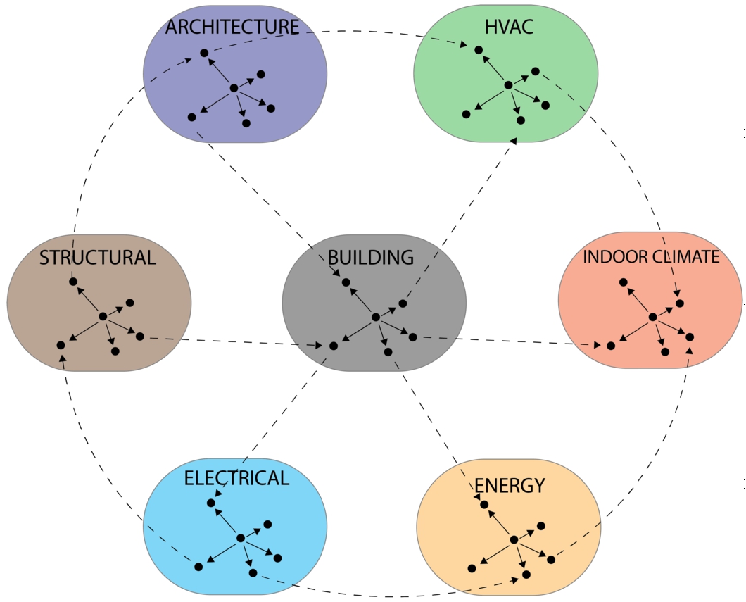
Contrary to the IFC schema, which has well-known limitations such as limited expression range, difficulty partitioning of information, and multiple ways of describing the same information, the W3C suggests more modular, polylithic, and simple data formats, also called ontologies, that can be interlinked and easily extended over time [29,40,43]. Figure 1 shows the concept of interconnected ontologies, and it can be seen that the domain-specific ontologies can be separated as smaller graphs and linked with other ontologies. An ontology does not need to cover an entire domain, such as HVAC systems. It can also cover minor subdomains for HVAC, such as representing different component types and their properties alone or the connectivity of HVAC components and their relations to systems and subsystems. Developing smaller ontologies that target one building domain will yield a practical and flexible way of modelling knowledge when combined [21,58].
1.3.Interlinking domain-specific knowledge
In this context, the World Wide Web Linked Building Data Community Group (W3C LBD CG) has defined and shared a set of ontologies like Building Topology Ontology (BOT) [42], Flow Systems Ontology (FSO) [27], TUBES System Ontology (TUBES) [37], Property Set Definition Ontology (PROPS) [7], and Product Ontology (PRODUCT) [67] for the AEC industry. While FSO describes the energy and mass flow relationships between systems and their components and their compositions [27,37], it lacks system components’ capacity- and size-related properties. A key aspect here is whether such properties need to be added directly to the FSO ontology or can be kept separate, e.g. in its own module or ontology. In Section 3 we argue that the best approach to create an ontology, called the Flow Properties Ontology (FPO), that includes only those properties and aligns it with other existing ontologies in the LBD CG context, in particular with the FSO ontology that focuses on HVAC domain.
1.4.Conforming domain-specific knowledge
Despite their strengths in representing domain-specific knowledge, ontologies cannot solve the problem that many BIM models are poorly modelled and lack building elements or metadata. Currently, poor data quality in building models contributes to faulty design decisions and downfalls in the information stream. Due to the increasing level of information, it is challenging to create sufficient BIM models [24,40,46,60]. Architects and owners can spend hundreds of hours manually assessing conformity [26]. Due to the time-consuming process and the need for high-performing BIM models, many research publications have addressed conformance checking. The most prominent publications on conformance checking of BIM models cover various frameworks, tools, rule languages, rule models, and rule engines [5,8,12,13,19,22,30,36,49,53,54]. As their data models rely on IFC or their rule models lack semantic expressivity, they all have limitations and cause poor query performance [28,51]. Soman et al. [55], Stolk and McGlinn [56], and Oraskari et al. [35] describe a promising approach to surpass the limitations of IFC and improve conformance checking. They use a Semantic Web approach with a data model written in OWL and a rule model written in SHACL to verify constraint violations. Soman et al. [55] applied the method to the construction field, while Stolk and McGlinn [56] applied the method to the geospatial field, and Oraskari et al. [35] to the energy simulation field. However, these publications do not describe how to validate an HVAC model with SHACL, nor do they apply the framework to a real-world large building project. In addition, we intend to develop a rule model written in SHACL for validating HVAC-related constraints.
1.5.Contribution
Considering the above, several innovations are needed. In fact, our research includes five contributions. Firstly, our research aims to extend FSO to support an alignment with the proposed FPO ontology. Secondly, we propose the FPO ontology itself to represent HVAC components’ capacity and size-related properties. Thirdly, we propose a set of rules to validate HVAC-related constraints. Fourthly, our work produces a demonstration environment for a real-world building project, showcasing how to conform a HVAC model using Semantic Web technologies. Lastly, the demonstration environment will showcase how FPO and the HVAC rule model can support the description and validation of hydraulics in HVAC components and the capacity of HVAC components.
1.6.Outline
The remainder of this article is structured as follows. Section 2 describes previous work on knowledge representation and rule checking related to buildings and systems. The presented work is limited to OWL-based data models and SHACL-based rule models. The development of FPO and extension of FSO are explained in Section 3. Section 4 outlines our framework and rules for validating HVAC-related constraints. We utilize a real-world building model in Section 5 to illustrate how FPO can represent capacity- and size-related properties and be used to design an HVAC device. Additionally, the real-world building model will be validated against our rule model in Section 5 where a process of four steps and a web application are introduced and applied to generate validation and capacity design results and display the results within a web interface. The validation results pinpoint the components or properties in the data model that violate our rule model, while the capacity results show the flow rate and pressure of each flow-moving device that is represented in the data model.The validation and capacity design results are discussed in Section 6, and conclusions are presented in Section 7. Table 1 shows the namespaces and prefixes used in this article.
Table 1
Used prefixes and namespaces
2.Background
2.1.Scope of the HVAC domain
The HVAC engineer is responsible for designing a building’s HVAC system. The purpose of an HVAC system is to provide building occupants with acceptable thermal comfort and indoor air quality. HVAC engineers must go through a series of steps to design an HVAC system, such as defining the distribution strategy for HVAC, defining the control strategy, calculating HVAC demand by zones, and determining the capacity and size of HVAC systems and their components. To determine whether an HVAC system is designed sufficiently, its cooling, ventilation and heating effects are compared with the building’s cooling, ventilation, and heating demands. The HVAC system is considered sufficient when the capacity exceeds the building’s demand. The HVAC engineer must design each HVAC component’s capacity individually since an HVAC system’s capacity equals the sum of its components. The HVAC component’s size is then determined based on its capacity. The HVAC engineer can choose a product from a manufacturer once the capacity and size have been defined. By the time all HVAC components have been designed, the HVAC engineer has completed the HVAC design process.
Since our research project seeks to represent and validate an HVAC system’s and HVAC component’s capacity and size-related properties in a Semantic Web context, Section 2.2 provides an overview of what research has been achieved in this field and what is missing.
2.2.System representation in a Semantic Web context
A number of ontologies have been proposed to handle data within the AEC industry since the early 2000s. The first significant contribution towards moving BIM data into the Semantic Web is the ifcOWL ontology. IfcOWL is an OWL representation of the IFC schema [6,59], and it is available at the buildingSMART website11 as just another serialisation of the IFC schema, next to eXtensible Markup Language Schema Definition (XSD) and EXPRESS [25]. It is recognized that IFC is not the easiest method to model a building or infrastructure due to the complex relationships between building elements (mostly n-ary relationships), which makes extension difficult. Hence, this has hampered its direct use among AEC stakeholders [1,57]. Moreover, it covers a wide range of domains, making it monolithic, rigid, and hard to extend [41]. The direct translation from the IFC schema to an OWL ontology does not change these inherent features of IFC, and so also, the OWL ontology has the same limitations (complexity, limited extensibility, size). However, the comprehensive nature of IFC also serves as its strength. It offers an all-encompassing framework for building information modelling, catering to a diverse range of building aspects. This extensive scope makes IFC a valuable resource in contexts where a detailed representation of various building domains is required. In response to the need for a more simplified and manageable approach, particularly in applications where such extensive detail is not necessary, several ontologies have been developed. These include the BOT, Smart Applications REFerence (SAREF), FSO, and others. Each of these ontologies abstracts a subset of the information covered by IFC into simpler and more manageable formats. For example, BOT focuses specifically on spatial elements, while SAREF and FSO concentrate on aspects like smart appliances and building services respectively. By extracting specific aspects from the broad spectrum covered by IFC in a simplified way, these ontologies offers a lightweight and domain-driven approach to building information modelling, complementing the comprehensive scope of IFC [42].
The next paragraphs present the ontologies that are relevant in the building service systems domain.
BOT describes the relationship between building zones and elements [44]. A zone can be a building, a floor, a space, or a group of spaces. The building can be connected to the floor level by asserting that an entity of bot:Building is related to an entity of bot:Storey with bot:hasStorey. The same method can be applied between the storey and the space. Zones are related in BOT by nesting smaller zones in larger zones. BOT can be used to describe the connections between zones in a building, but it cannot describe building systems.
SEAS describes the relationships between physical systems [31]. There are three main modules in the ontology, namely, The System Ontology, The Features Of Interest Ontology, and The Evaluation Ontology. The Features Of Interest Ontology allows us to describe features of interest and their properties. A car, as an example, can be considered a feature of interest with a property called speed. Properties are either evaluated directly or through a qualified evaluation in the Evaluation Ontology. In a direct evaluation, a value is assigned to the property. A qualified evaluation needs to outline three categories: type, the context of validity, and provenance data. The System Ontology describes the systems and the relationships between them. There are three levels of connectivity: between systems, connections, or connection points. The SEAS ontology focuses primarily on electrical systems but can also be used to represent higher-level building services systems [31]. Yet, it does not describe any building service components or their relationships to building service systems.
Building service components are included in the Brick ontology [4] and the SAREF ontology [9] at different conceptual levels and scopes. The emergence of semantic modelling in building systems has been significantly influenced by the collaboration and development of standards and frameworks like Brick, Project Haystack, and American Society of Heating, Refrigerating and Air-Conditioning Engineers (ASHRAE) Standard 223P [3].
The Brick ontology describes sensor points and their relationships to physical, logical, and virtual assets in buildings. It consists of a core ontology to describe fundamental concepts and their relationships and a domain-specific taxonomy. The ontology focuses on sensor points and their relations to location, equipment, and resource [4]. Relating a sensor point to a location expresses in which area of the building the sensor point is located. It can be located in a room, on a floor, in a duct. Relating a sensor point to specific equipment expresses how the sensor point controls the system or component. For example, take a room temperature sensor positioned in a room. The room temperature sensor regulates how much air an Air Handling Unit (AHU) must supply to the room. Lastly, the resource is the medium being measured and regulated by the sensor point and equipment. For example, the medium of an AHU is the air that is being supplied to a room.
ASHRAE Standard 223P, developed in collaboration with Project Haystack and the Brick initiative, aims to standardize semantic modeling in building systems. This standard represents a significant step towards unifying the approach to building data semantics, building upon the foundational work of Haystack tagging and Brick data modelling concepts [3].
The SAREF Smart Appliances Reference ontology is a reference ontology for smart appliances (devices) [9]. It aims to bring meaningful interactions between Internet of Things (IoT) devices in various domains. There are currently 13 extensions to the core ontology. SAREF4SYST is based on the concepts of seas:SystemOntology to describe higher-level building service systems. SAREF4BLDG is based on the IFC taxonomy and describes building service devices. Even if it is similar to IFC and BOT, these structures are not fully the same [39]. Together, SAREF4SYST and SAREF4BLDG can represent building systems and their connectivity with IoT devices. Like Brick, the SAREF ontology represents medium-level building system devices such as a fan or pump. Furthermore, SAREF4BLDG represents capacity-related building service devices to some extent. Those parameters are based on the IFC taxonomy.
However, while Brick, SAREF, and the initiatives leading to ASHRAE Standard 223P have significantly advanced semantic modeling, particularly focused on the operational phase of the building life cycle, they present limitations in certain areas. Specifically, these frameworks and standards primarily revolve around sensor points, leading to a notable exclusion of passive components, such as pipes and ducts, or their properties.
An OWL ontology that is similar to the SAREF4BLDG ontology, but does not include any building topology to avoid semantically overlapping ontologies, is the Mechanical, Electrical and Plumbing (MEP) ontology.22 This ontology is structured as a very simple hierarchical taxonomy for devices and is directly created based on the DistributionElement subtree in the IFC schema. It needs to be combined with the BOT ontology to be of use and works well to classify distribution elements such as air terminals.
FSO focuses on the design and operational phase of the building life cycle [27]. It describes the mass flow and energy relationships between systems and components and the composition of such systems [27]. FSO gives the ability to connect both passive and active components to systems and subsystems. For example, a heating system can include a supply and a return system as subsystems. A segment or fitting can be related to a supply or return system. A component can also be connected to a supply and return system, such as a heat exchanger. A segment can supply or return fluid to another component based on what system it belongs to. Unlike Brick and SAREF ontologies, FSO only represent higher-level components such as flow-moving devices or flow-controlling devices (also included in the MEP ontology). The taxonomy of building service devices for all four ontologies is based on the IFC taxonomy. However, FSO does not represent both active and passive components’ size- and capacity-related properties. Without that representation, HVAC engineers cannot design an HVAC system nor an HVAC component during the design phase using FSO.
FPO and an extended version of FSO are introduced in Section 3 to fill this research gap and describe the size- and capacity-related properties of both active and passive components within the design phase. Ontologies are mainly used to represent domain-specific knowledge. To check whether a BIM model lacks building elements or metadata, we need a rule language. Section 2.3 describes which rule languages exist and what research has achieved in this area in a Semantic Web context.
This overview of existing ontologies in the AEC industry, including ifcOWL, BOT, SEAS, Brick, SAREF, and others, aims to highlight both their strengths and limitations in relation to HVAC system representation. These ontologies lay the groundwork for our further research, where we introduce FSO and FPO. Building upon this existing knowledge base, FSO and FPO take a step further to address specific needs in HVAC system design. By focusing on capacity- and size-related properties for both active and passive components, FSO and FPO fill critical gaps left by these ontologies. This contribution is crucial for enabling more detailed and accurate design and compliance checking of HVAC systems in the building design phase.
2.3.Rule languages in a Semantic Web context
Several prominent rule languages have been developed by the W3C. In 2004, the W3C introduced the Semantic Web Rule Language (SWRL) as a member submission.33 SWRL is a combination of the OWL Description Language (DL) and OWL Lite sublanguages of OWL with the Unary/Binary Datalog RuleML sublanguages of the Rule Markup Language. OWL knowledge bases are integrated with Horn-like rules in the rule language. The rules are expressed in terms of OWL concepts, such as classes, properties and individuals. Because OWL ontologies are limited in their ability to express complex logical reasoning, SWRL allows users to create custom rules and apply them to OWL ontologies [32,61].
Similar to SWRL, the Rule Interchange Format (RIF) introduced in 2005 by W3C allows rules to be expressed in XML syntax. In order to enhance interoperability between rule languages, RIF was designed to be the standard exchange format for rules on the Semantic Web. As of today, RIF consists of 12 parts, including RIF-core, which is the core of all RIF dialects [32,64].
Notation3 (N3), is an assertion and logic language that supports expressing RDF-based rules. It was introduced in 2011 by W3C as a team submission to extend RDF by adding formulae, variables, logical implication, and functional predicates, as well as to provide an alternative syntax to the XML syntax that SWRL and RIF use. By using shortcuts and syntactic sugar, it is able to simplify statements in the form of triples [62].
The SPARQL Inferencing Notation (SPIN) was introduced by W3C in 2011 as a member submission and has become a de facto industry standard for describing SPARQL rules and constraints. The key feature of SPIN, compared to SWRL, RIF, and N3, is the ability to specify constraints using SPARQL queries. In this way, property values can be calculated based on other properties, or a set of rules can be isolated for execution under certain conditions. It is also possible to use SPIN to check the validity of constraints based on the assumption of a closed world [63].
SHACL is the successor to SPIN and was published as a W3C Recommendation in 2017 [20,65]. A higher status has been granted to SHACL by W3C in comparison to SWRL, RIF, N3 and SPIN. Distinguished from other Semantic Web technologies, SHACL is based on the Closed World Assumption (CWA). This approach means that in data validation, SHACL considers anything not explicitly stated in the dataset as false or non-existent, focusing on validating data against specifically defined constraints within this “closed world.” This feature of SHACL makes it particularly effective in scenarios where explicit and complete data validation is essential [66]. As a result, SHACL has become the web standard today for validating RDF graphs. SHACL is heavily inspired by SPIN, but it offers far more flexibility in defining target constraints. SPIN is limited to classes, while SHACL can be applied to classes or sets of nodes by various target mechanisms, including customized targets. Furthermore, SHACL advanced features allow validation of more complex constraint types, such as sub-graph pattern- and conditional validation. SHACL contains two major components:
Data graph: | A data model containing domain-specific knowledge. |
Shape graph: | A rule model consisting of user-defined constraints. User-defined shapes can be node shapes or property shapes. Node shapes specify constraints on target nodes, while property shapes specify constraints on target properties and their values. |
By separating the data model and rule model, SHACL follows the Business Rule Management Systems (BRMS) principle of decomposing knowledge into logic and data, enabling them to be independently manipulated [55]. In addition, SHACL outputs an RDF graph with validation results, which describes whether a data model passed or failed a given rule set.
The following section highlights the research gap based on an overview of recent research on applying SHACL to perform conformance checking within the AEC industry.
2.3.1.The research gap in case studies
Stolk and McGlinn [56] demonstrated how ifcOWL can be validated using SHACL. The authors showed how ifc:lengthValue_IfcQuantityLength can be restricted to only have values of type ifc:IfcLengthMeasure and how cardinality constraints can be used to restrict ifc:IfcDoorPanel properties.
Hagedorn and König [20] developed an approach for compliance checking linked building models. The proposed method implements the four steps mentioned by Eastman using Semantic Web technologies. Using the IFC2RDF converter, the authors converted an IFC schema into ifcOWL. Their rule model involved a set of rules to validate the path between an identifier of a link and the original identifier. In order to validate their data model against the rule model and receive a validation report, they used the W3C SHACL Test Suite.
To define and check complex and dynamic scheduling constraints in construction, Soman et al. [55] developed a linked-data-based constraint-checking approach utilizing Semantic Web technologies. The approach was implemented through a web application that validated construction scheduling violations using different types of constraints. The pySHACL library was used to define and validate SHACL shapes, and the RDFlib library was used to design and store a RDF graph. They used IfcOWL and LinkOnt to capture the model information of a real-building model.
Oraskari et al. [35] defined rules within the energy simulation field for validating windows of specific sizes, checksums of properties, and alignments of BOT classes and properties. They validated two data models against each other in order to align BOT classes and properties with ifcOWL. The IFC schema of a conceptual building model was converted to ifcOWL and BOT using the IFCtoLBD and IFC2BOT converters. The rule modelling, validation and reporting were performed using the TopBraid SHACL Application Programming Interface (API).
While previous studies have utilized SHACL in various domains, none have specifically focused on HVAC systems in BIM models. This study introduces a SHACL-based rule model tailored for the HVAC domain, utilizing lightweight ontologies like FSO and the newly proposed FPO to define HVAC systems and components within a data graph. This targeted approach not only meets the unique design requirements of HVAC systems but also ensures the integrity and reliability of HVAC data in BIM models. Crucially, this study contributes to bridging the information gap in HVAC information management by developing a SHACL-based HVAC rule model. Such an advancement is key for enhancing HVAC data integrity in BIM environments, thereby addressing a critical need in the AEC domain.
3.Flow properties ontology
FPO is developed as an extension to FSO [27] to represent FSO component’s capacity and size-related properties. The decision to develop FPO as an extension to FSO instead of integrating its concepts and relationships directly into FSO is driven by the desire to maintain simplicity and ease of use in the core ontology. By keeping FSO minimalistic and general, it remains accessible and adaptable. FPO adds the necessary depth and detail for capacity and size aspects in certain HVAC subdomains without complicating the core system (FSO). This approach ensures that FSO and FPO can evolve and adapt over time with ease, are straightforward to maintain and update and remain user-friendly for all levels of expertise. This design philosophy mirrors that of the SAREF ontology [9], which employs a core ontology for fundamental concepts, expandable through specific modules for different areas.
FPO contains 50 classes, 50 object properties and 6 data properties and has a Description Logic expressivity of
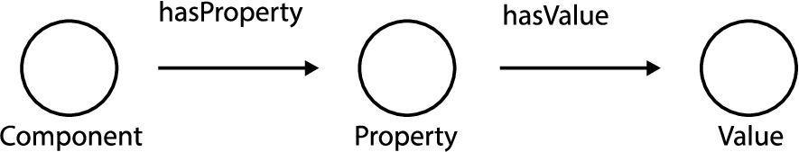
It is necessary to know the HVAC component type to describe its properties. A property of one HVAC component may differ from another, and the data type or unit of one property may vary from another property. A pump has different properties than a fan, and the flow rate can be expressed in liter per second or cubic meters per hour, which is different from a ventilation fan. An elbow can differ in properties from a tee by having an angle, even if both are fittings. Moreover, a tee has three flow ports, and an elbow has two flow ports. Conceptually, Fig. 2 illustrates how a component can have a property and the property a value. As there are two steps between the component (Type / Object) and the value, this property modelling approach is a Level 2 (L2) property modelling approach, as defined by Bonduel and Pauwels [38].
Fig. 2.
Relationship between components, properties, and property values.
It is possible to represent buildings, spaces, and their relationships with systems and components using FSO and BOT. Adding FPO, the representation can identify whether a particular system or component is able to heat, cool, or ventilate a specific building or space.
The following subsections provide a more detailed description of FPO. To determine the scope of the ontology, Section 3.1 lists a set of competency questions. In Section 3.2.2, FSO is extended with medium-level components to represent fluid movements between components. Section 3.3 reviews FPO classes and their properties. Finally, reasoning examples will be enabled in Section 3.4. Both the extension of FSO and the development of FPO are made available on GitHub.44
3.1.Competency questions
Competency questions in Table 2 are central to evaluating the practical applicability and relevance of the FPO in the field of HVAC engineering. These questions were formulated based on the typical needs encountered by HVAC engineers. Each question highlights a critical aspect of the HVAC design process:
System Capacity (CQ1): This question assesses FPO’s ability to represent the capacity of an HVAC system to meet a building’s demands for heating, cooling, and ventilation. It’s crucial to ensure that the system can adequately fulfill the environmental comfort needs of the building, contributing to its efficiency and suitability.
Component Capacity (CQ2): This focuses on the capacities of individual HVAC components, such as pumps and fans, and their role in supporting the overall system. The capacity of each component is vital to ensure it contributes effectively to the system’s ability to provide heating, cooling, and ventilation, thus maintaining the system’s overall performance and efficiency.
Component Size (CQ3): The size of HVAC components directly impacts their capacity and is integral to sizing analysis. Accurate size information is essential for selecting appropriate components from manufacturers. Ensuring the chosen products match the designed dimensions confirms their fit in designated spaces.
Table 2
Competency questions
| Reference | Competency question |
| CQ1 | What is the heating, cooling or ventilation capacity of a system? |
| CQ2 | What is the heating, cooling or ventilation capacity of an HVAC component? |
| CQ3 | What is the size of a given HVAC component? |
The scope of the ontology, as outlined by these questions, is further validated in Section 5 through SPARQL queries.
3.2.Flow system ontology extended
3.2.1.Connection between components
FSO represents the energy and mass flow relationships between systems, their components, and their composition. However, the current version of FSO cannot express the magnitude of these flows. Real-world components contain fluid in motion, flowing in and out through openings and passages, i.e. ports, which vary considerably in size, impacting pressure drop and flow rate, e.g. capacity. Without representing these size and capacity-related properties, FSO cannot fully capture the nuances of fluid dynamics, crucial for accurate HVAC component and system design. As a result, incorporating fso:Port into the ontology is essential to capture fluid dynamics. By extending the FSO taxonomy to include fso:Port, we enable a detailed hierarchical relationship among systems, components, and ports, enhancing the accuracy and utility of the FSO model for HVAC engineers.
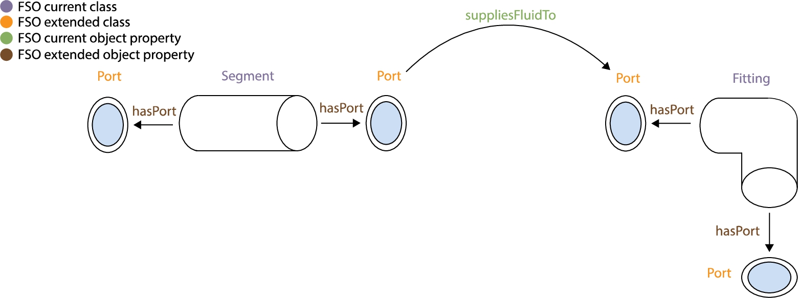
The concept of relating a fso:Port for multiple components is shown in Fig. 3. An fso:Segment can be linked to an fso:Port with fso:hasPort. With fso:hasPort available, an fso:Fitting can be related to its ports. The direct relationship between the ports of both components is expressed using fso:suppliesFluidTo.
Fig. 3.
A segment partitioned with ports connecting to a fitting through its ports.
A relationship can be described among systems and components as shown in Fig. 4. The components share the same fso:ConnectionPoint. Flows and Ports are not available in this example but could be modelled as well, after the example in Fig. 3.
Fig. 4.
Current and extended taxonomy of FSO with connection points.
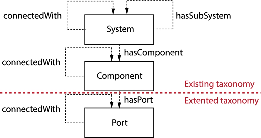
The proposed extension to FSO makes it capable of representing components and interfaces in multiple ways, which adds some flexibility. The definition of the mentioned classes and relationships in this section is defined as follows:
fso:Port is defined as “An opening or passage that directs the flow of a mass or energy”.
fso:hasPort is defined as “The relation from a component to a port.”
3.2.2.Extended component abstraction level
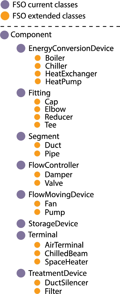
Currently, FSO represents eight high-level component types. For several reasons, we must subdivide the eight high-level component types into 19 medium-level components. For instance, the hydraulic sizing of a pump or a fan is different. The sizing of a pump includes the pressure drop from both supply system components and return system components, but the sizing of a fan only includes the pressure drop of either supply or return side. We have to define the types explicitly when performing hydraulic calculations.
Often components lack the required properties to perform a hydraulic calculation. For example, if an elbow does not have a specified angle, we will not be able to differentiate between an elbow or transition since they both are represented as a fso:Fitting and have two ports. To accommodate the difference in properties, the eight high-level FSO components have been nested into 19 medium-level components as shown in Fig. 5.
Fig. 5.
A class hierarchy of current and extended FSO components.
3.3.Property relationships
FPO provides 6 data properties: value, unit, abbreviation, design condition and curve. They can be used to relate an entity literal to an entity class. Combined, the 50 classes, 50 object properties and 6 data properties represent the size and capacity of the FSO components.
In property modelling, there are different levels of complexity. Level 1 (L1) property modelling is a straightforward approach where properties are directly linked to a component. For instance, in an L1 model, a property like fpo:hasLength would be directly associated with a component such as a pipe, typically using a direct data property like fso:Pipe fpo:hasLength
Fig. 6.
Describing the relationship between an fso:Segment and its properties with FPO classes, object and data properties.
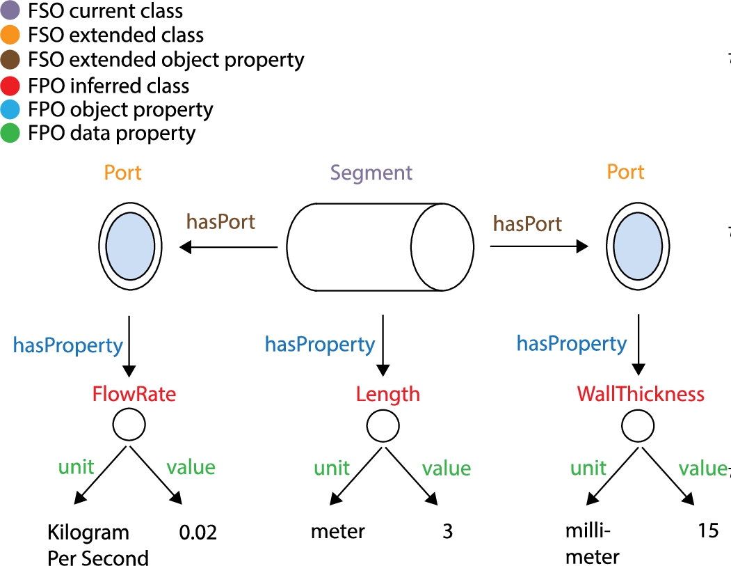
However, Fig. 6 demonstrates a more complex approach, where we apply the Level 2 (L2) property modelling approach as defined by Bonduel and Pauwels [38]. In this approach, an fso:Segment can be related to the property fpo:Length with fpo:hasProperty. This relationship is then further specified with fpo:hasValue and fpo:hasUnit, connecting fpo:Length to the value
The adoption of the L2 approach in FPO is driven by the need for structured flexibility and scalability in representing HVAC properties. This model allows each property, such as fpo:Length, to have its own set of attributes like value and unit. Moreover, it can accommodate the addition of metadata, such as timestamps, enabling the representation of both static and dynamic property values. This aspect is crucial in the HVAC domain, where property values can change over time or under different conditions. By using the L2 approach, FPO effectively captures the diverse and dynamic nature of HVAC properties, avoiding the complexity of an excessive number of data properties. This modelling choice aligns with our objective to create an ontology that is comprehensive in its domain representation and adaptable for future extensions.
3.4.Reasoning
Semantic Web technologies enable deductive reasoning as well as explicit assertions. A few examples of how FPO and the extended FSO allow for reasoning are presented in this section. Every object property in FPO is assigned a domain and a range. For example, the attribute fpo:hasLength has the domain fso:Component and range fpo:Length. This means that whenever we have a subject of type fso:Component and a predicate of type fpo:hasLength, then the object must be of type fpo:Length. This also means that a reasoning engine will automatically infer the class fpo:Length when the object property fpo:hasLength is provided in the input instance data. This can similarly be done for all the other properties shown in Fig. 6.
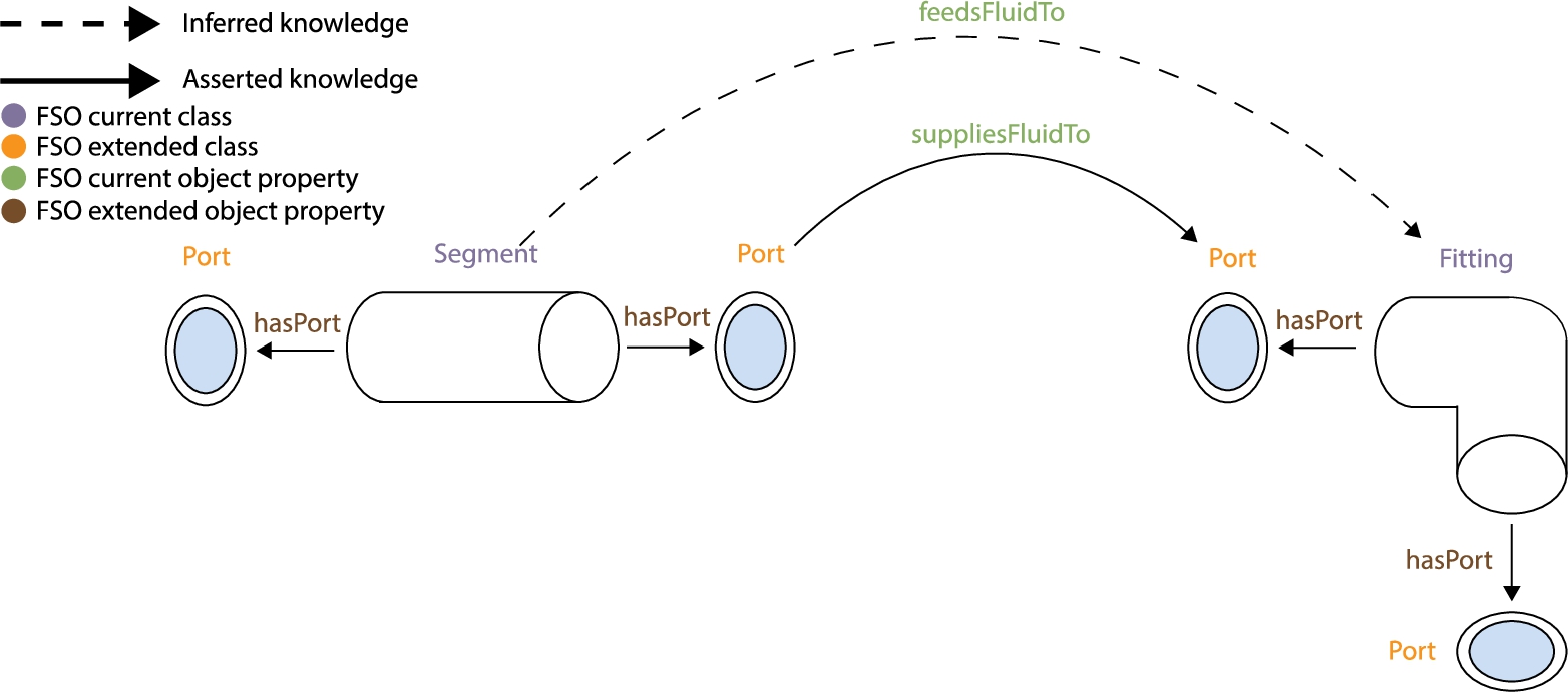
An fso:Segment is shown in Fig. 7 supplying fluid to an fso:Fitting with the property fso:suppliesFluidTo. However, with the extended FSO, it is possible to infer that if a segment port supplies fluid to another port of a fitting, then the segment must also feed fluid to the fitting (transitive object property). Figure 7 illustrates the inferred knowledge.
Fig. 7.
Deducing that the segment feeds fluid to the fitting as a port of the segment supplies fluid to a port of the fitting.
In addition to the specific reasoning capabilities within FPO, it’s important to note how the ontology operates under the Open World Assumption (OWA). This means that if FPO lacks data on a specific property, such as the flow rate of a pump, it doesn’t presume the information to be non-existent; rather, it’s understood as not currently known or included in the ontology.
When new information becomes available, like a previously unknown flow rate, FPO can incorporate this data seamlessly, allowing the ontology to adapt and evolve over time. This reflects the dynamic nature of HVAC system properties and their changing characteristics.
In practice, when querying a triplestore using FPO, missing data is presented as unknown rather than non-existent, conforming to the principles of the OWA. This approach ensures a realistic and dynamic representation of HVAC components’ properties, essential for accurate modelling and analysis in ever-evolving HVAC environments.
4.HVAC rule model
The HVAC rule model, comprising 36 shapes and 122 constraints, is specifically designed to pre-validate HVAC data models to ensure they contain all necessary information for hydraulic calculations. Accessible on GitHub,55 this model checks the composition of HVAC components, their systems, and their capacity and size-related properties. Key functionalities include determining whether a specific HVAC component is part of a system, verifying flow ports and connections to other components, and checking their size- and capacity-related properties such as flow rate and diameter. Additionally, the model ensures that all HVAC components are interconnected from end to end. In this context, the FSO and FPO are required for representing HVAC systems and components. However, the core validation of these representations is conducted using our SHACL-based HVAC rule model. In our model, we employ only hard constraints, as the absence of weak constraints signifies that any data model violation renders it unsuitable for the hydraulic calculation task. This approach, focusing on specificity rather than a generic, all-encompassing rule model, allows for the creation of modular rule models, each designed for distinct HVAC tasks.
Building upon this foundation, Eastman et al. [15] propose a four-step manual approach for rule-based compliance checking. This methodology is significant as it enables us to apply targeted corrections bypassing the time-intensive and error-laden process of manually inspecting large and complex BIM models. The steps include:
1. Rule interpretation: Human-readable rules are converted into a machine-interpretable format that contains the information needed to be checked in the correct format, also known as the rule model.
2. Building model preparation: Building information is converted into a machine-readable format, also known as the data model.
3. Rule execution: The data model is validated against the rule model.
4. Rule check reporting: A validation report describing whether the data model has passed or violated any constraints.
While this approach provides a comprehensive framework for compliance checking, it remains primarily passive, identifying whether constraints are met or violated. To address this, Solihin et al. [52] introduce a proactive fifth step for automatic correction, empowering users or systems to not only be notified of violations but also to receive corrective data, with options for automatic or manual implementation.
Furthermore, Solihin et al. [52] suggest categorizing rules based on their complexity, ranging from 1–4:
Class 1: | entities and attributes are queried and checked against a single value. |
Class 2: | additional values are calculated (e.g. distance) and checked. |
Class 3: | additional geometry is created in order to calculate spatial relationships. |
Class 4: | problem solutions are calculated, and new data is created. |
This section will demonstrate how a SHACL-based rule can be designed for each complexity level, tailored specifically to the HVAC domain.
4.1.Verifying pipes explicitly
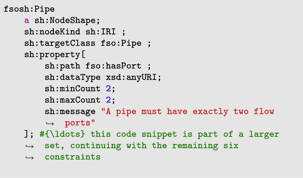
In hydraulic calculations, it is essential to know the location of each pipe segment in relation to upstream and downstream HVAC components, as well as its roughness and length. Understanding the placement of HVAC components in relation to other components helps determine how fluids like air or water move through the system. “Upstream” refers to components that come before the pipe in the fluid’s flow direction, while “downstream” refers to those that come after. The roughness and length of the pipe are also crucial for calculating how efficiently the fluid moves through the system. The shape fsosh:Pipe applies 7 constraints to an fso:Pipe and has a complexity level of 1 and is described as follows:
Constraint 1: | An fso:Pipe must have exactly two flow ports. |
Constraint 2: | A pipe must feed fluid to exactly one component. |
Constraint 3: | A pipe must be fed with fluid by exactly one component. |
Constraint 4: | A pipe must be connected to exactly one system. |
Constraint 5: | Exactly one property of material type must be present in a pipe. |
Constraint 6: | Exactly one property of length must be present for a pipe. |
Constraint 7: | Exactly one property of roughness type must be present for a pipe. |
In Listing 1, only the first constraint is expressed in SHACL. The remaining 6 SHACL constraints are made available on GitHub.66 In the first constraint, the cardinality constraints sh:minCount and sh:maxCount are applied to check that the fso:Pipe has two ports. A minimum and maximum cardinality of 2 will satisfy this constraint. In addition, we use the value type constraint sh:dataType with the value xsd:anyURI to ensure the triple includes a URI. If the cardinality constraint or value type constraint is not satisfied, the message “A pipe must have exactly two flow ports” will be thrown.
Listing 1.
A SHACL shape to constrain the number of fso:Port with fso:hasPort for each fso:Pipe
4.2.Verifying the demand versus capacity by derived information
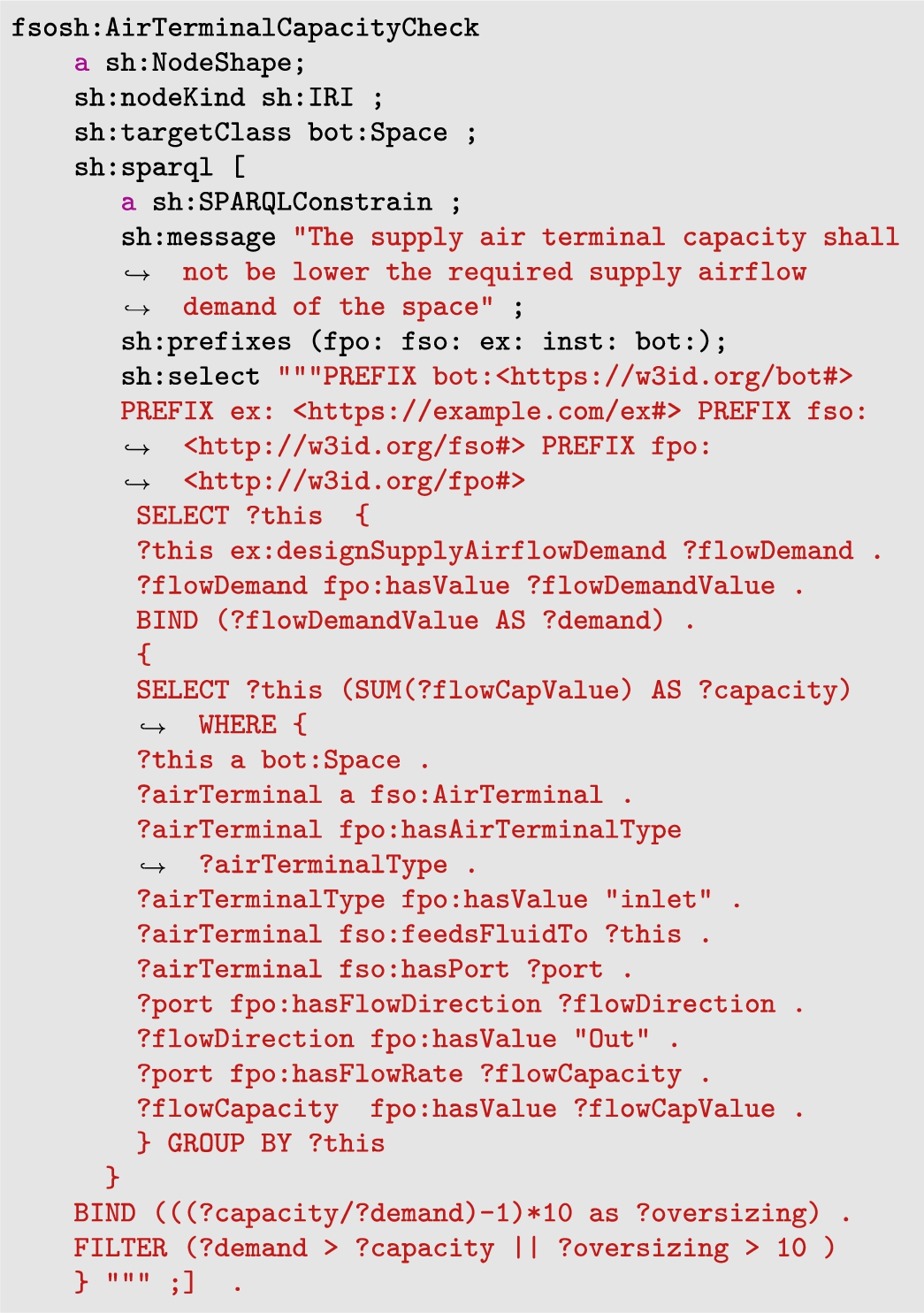
HVAC systems and their components must be designed to provide sufficient heating, cooling, and/or ventilation to buildings. For example, an HVAC terminal is designed correctly if its capacity to heat, cool, and ventilate a space exceeds the space’s demand. With the following constraint, we demonstrate how the capacity of a supply air terminal can be compared with the supply airflow demand of a space:
Constraint 1: | The supply air terminal capacity should be higher than the space’s required supply airflow demand. |
The rule is expressed in a single SHACL shape, as shown in Listing 2, and the constraint belongs to the shape fsosh:AirTerminalCapacityCheck. A SPARQL-based constraint is used to implicitly find the comparison between capacity and demand since it is not explicitly defined. Because this rule requires derived information, it reaches complexity level 2. A nested SPARQL select query is shown in Listing 2. There can be more than one supply air terminal in a space. To sum the capacity of all air terminals grouped by space, we apply an inner select query. In the outer select query, we find the supply airflow demand for each space and filter them according to the constraint. This rule will be violated when the supply air terminal capacity exceeds the supply airflow demand of the space.
Listing 2.
The listing shows a SHACL shape to constrain the capacity of a supply air terminal versus the supply airflow demand of a space
4.3.A rule of thumb to verify pressure drop in pipes
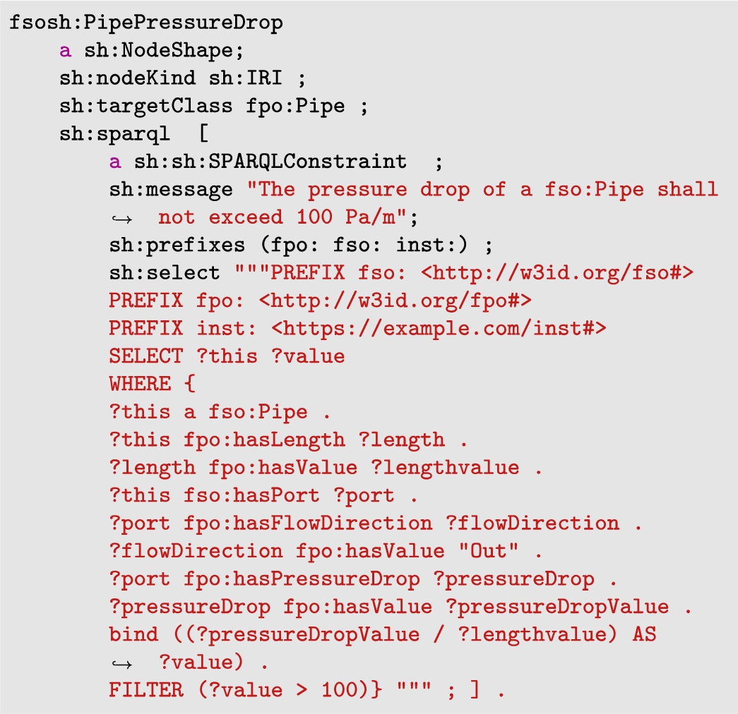
The pressure drop in pipes affects the economy of building projects, the material’s lifetime and the energy consumption of HVAC systems. A high-pressure loss will result in a lower cost price, a shorter lifetime, and higher energy consumption. As a result, most HVAC engineers apply guidelines to their design, e.g. a maximum pipe pressure loss of 100 Pa/m. This guideline or rule cannot be conveyed through explicit information. Calculations and derived information are also required. The complexity level of the shape fsosh:PipePressureDrop reaches 3 because an engine is used to calculate the pressure drop and velocity of each distribution component. The engine is discussed in detail in Section 5.1. The only constraint in this rule is targeting an fso:Pipe and is described as follows:
Constraint 1: | The pressure drop of a fso:Pipe shall not exceed 100 Pa/m. |
Listing 3 shows the rule expression in SHACL. The pressure drop in pipes is not explicitly defined in Pa/m in FSO or FPO. We can, however, implicitly find the information using a SPARQL constraint. Our SPARQL-based constraint contains a SPARQL select query. The select query returns all instances of fso:Pipe that exceeds 100 Pa/m in pressure drop. By dividing the length of the pipe by the pressure drop at the outlet port, we can determine the pressure drop in Pa/m for each fso:Pipe instance.
Listing 3.
A SHACL shape to constrain the maximum pressure drop of each fso:Pipe
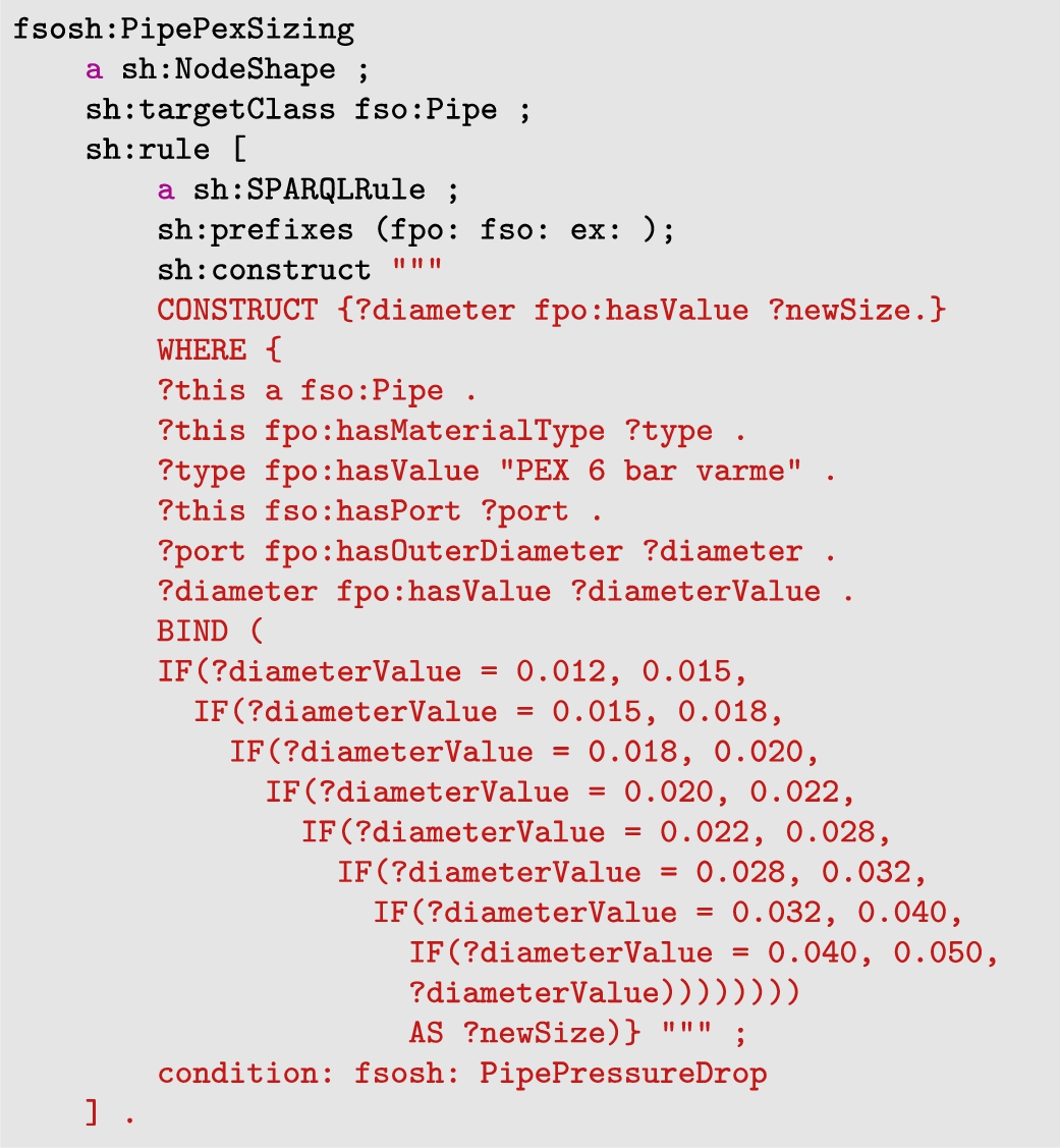
4.4.Redesigning the size of pipes automatically
During the HVAC design process, HVAC components are often oversized or undersized due to limited time. Rather than just creating a rule that notifies whether HVAC components are right-sized passively, we will generate new data actively and add it to the model. By increasing the diameter of the pipe, we can decrease the pressure drop. That is precisely what Listing 4 is doing. Listing 4 is an inference rule expressed in SHACL. Using a SPARQL construct query, the pipe diameter is increased based on the material type and standard manufacturer size. The dimensions are limited to the material type PEX77 and range from 0.012 to 0.050 meters. For every fso:Pipe that violates the previous rule, fsosh:PipePressureDrop, the active rule generates a new diameter. For instance, a pipe diameter of 0.012 meters will automatically be increased to 0.015 meters and added to the data model. Since this rule can generate new information, it reaches a complexity level of 4.
Listing 4.
A SHACL shape to increase the size of a fso:Pipe automatically
5.Demonstration environment
This section aims to demonstrate how capacity and size-related properties within the HVAC domain can be represented and validated for a real-world BIM model. The use case process is illustrated in Fig. 8.
Fig. 8.
The process of performing conformance checking and design calculations for an HVAC model.
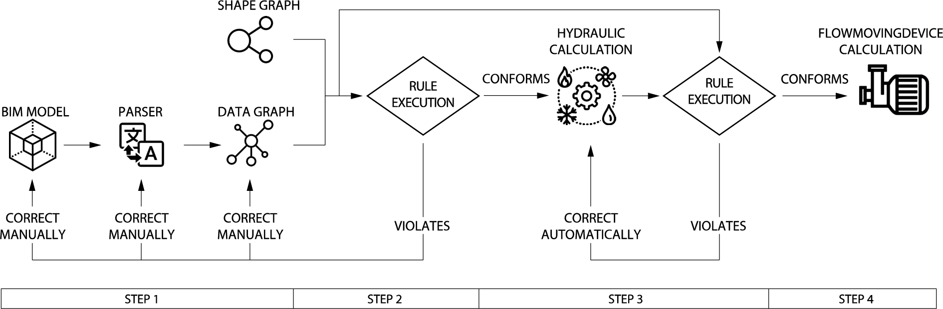
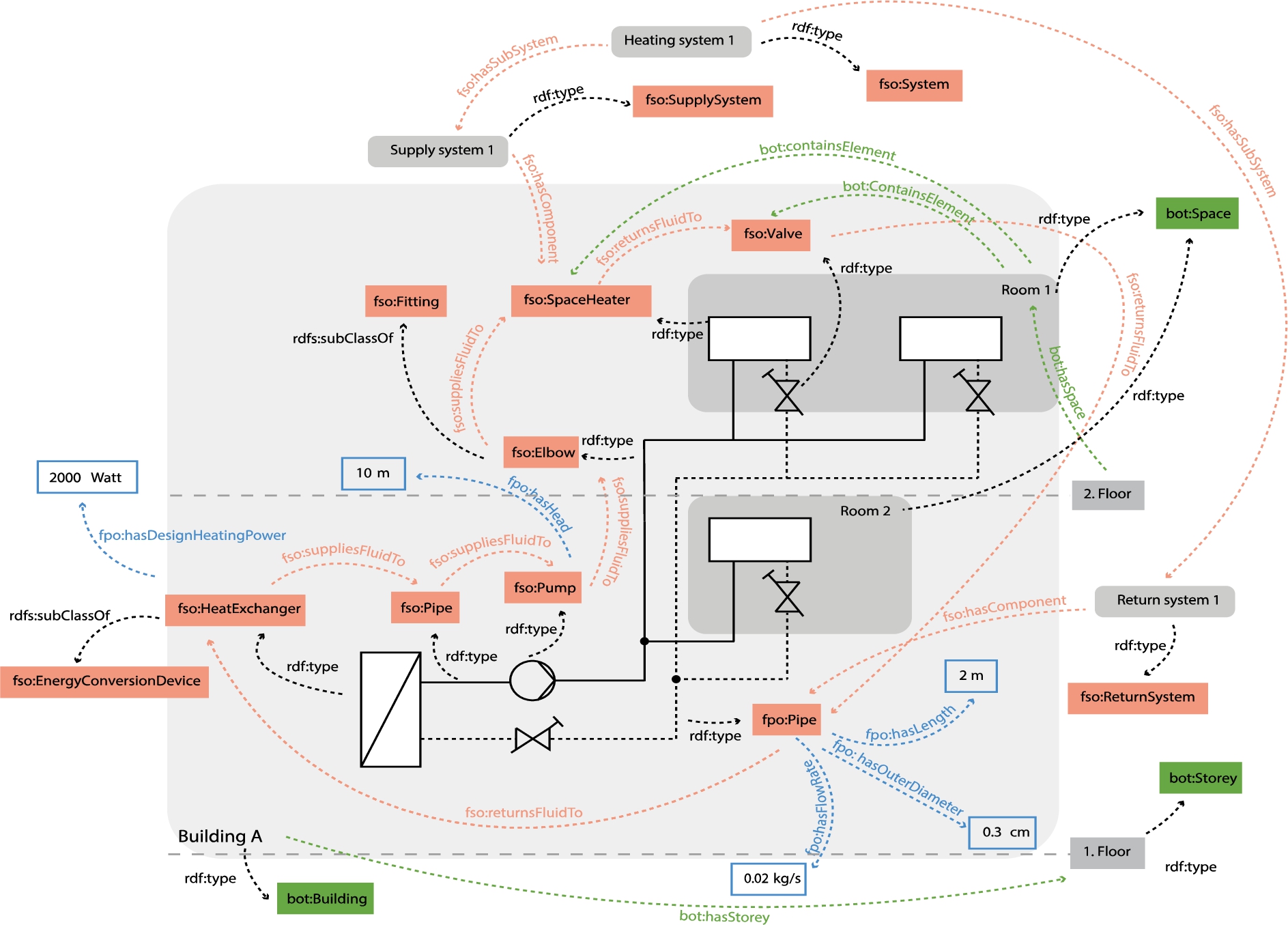
The first step of the process is to create a data graph and shape a graph. As the shape graph is already produced in Section 4, it does not require further processing and can be used as-is.88 In contrast, converting a BIM model will create the data graph. This step is identical to the building model preparation phase of Eastman et al. [15]. The data graph contains BOT, FSO, and FPO vocabularies so that it matches with the rules in our shape graph and can proceed to the rule execution phase of Eastman et al. [15]. Using these three vocabularies, we can describe the building, its services, its interactions, and its properties. For example, we can express how the HVAC system or an HVAC component relates to the building or a specific room. Figure 9 shows the relation between BOT, FSO and FPO. The figure also illustrates how this network of ontologies can be used to represent the relationship between a heating system, its components, properties, and the building it serves. It simplifies the relationship between the HVAC components and their properties for illustration purposes.
Fig. 9.
Combining multiple ontologies to represent building, spaces, systems, HVAC components, their properties and their relationships.
In the second step, a rule execution process will be performed to check the shape graph against the data graph. The data graph will be manually corrected if any constraints are violated during rule execution. Depending on the violation type, manual correction can be achieved at three levels: BIM model, parser, or data graph. In cases where we do not want to modify the BIM model, we can use SPARQL on the data graph or add the information through the parser.
When the rule execution conforms, we can proceed to step 3. This step involves hydraulic calculations for ducts, pipes, and fittings to determine each distribution component’s pressure drop and fluid velocity. These hydraulic results will then be materialized in the data graph, facilitating a second conformance check. This check involves comparing the shape graph against the data graph, now including the hydraulic calculations. Whenever a constraint is violated, an HVAC rule at level 4 in complexity from the shape graph will be used to correct the violation.
When the rule execution conforms, we will have all the information necessary to size the flow-moving device. Step 4 will therefore involve calculating the capacity of each flow-moving device, represented in the data graph. After the flow-moving devices’ capacities have been calculated, the result is given, and the process ends.
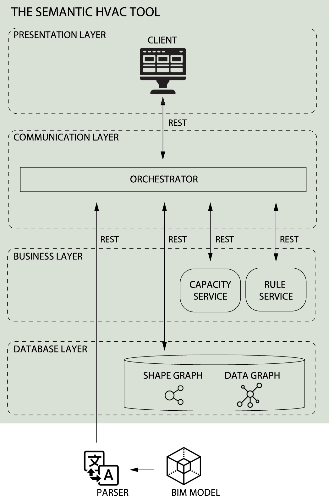
5.1.A Semantic HVAC Tool
We developed the Semantic HVAC tool to perform the process shown in Fig. 8. The web tool has a microservice-oriented system architecture and contains four layers, which is illustrated in Fig. 10. The source code of the Semantic HVAC Tool and the material used to perform the process shown in Fig. 8 is made available on GitHub.99 This design choice is part of a broader strategy at the Department of Mechanical Engineering, Technical University of Denmark, emphasizing clarity, modularity, and domain-specific functionality in development. Each microservice is designed to encapsulate business logic for a specific domain or subdomain, ensuring that the complexities of one service do not spill over into another. This approach enhances clarity and transparency, making it easier for students to understand, develop, and maintain each service independently. This architecture enables us to maintain a clean separation of concerns, where each component of the HVAC system – be it hydraulic calculations, flow-moving device assessments, or rule checking – has its dedicated microservice. Moreover, the central orchestrator serves not just as a communication hub but also as a means to preserve this separation, managing interactions between services without intertwining their internal logics. The following sections first describe the data flow in detail and then demonstrate the Semantic HVAC tool in a use case.
Fig. 10.
The system architecture of the Semantic HVAC Tool.
5.1.1.Presentation layer
The presentation layer handles the user interface logic and displays data on the page. The Graphical User Interface (GUI) relies on React components to improve page rendering [45]. Using the GUI, users can perform conformance checking, perform hydraulic calculations, calculate the capacity of flow-moving devices, and view the results. The user has to initiate the conformance checking and calculations in the right order, as shown in Fig. 8. It is, therefore, necessary for the user to initiate the conformance check first. The user must correct all violations manually if any exist. If any violation exists, the GUI will not allow the user to perform the hydraulic calculation. Using this method, we ensure that the data model contains all the information we need to calculate the hydraulics. The same applies to the capacity calculation of flow-moving devices. If any violations occur after the second conformance check, the GUI will not allow the user to initiate the flow-moving device calculation.
The GUI displays the conformance check results in two different tables. Based on the type of HVAC component, the HVAC system, and size and capacity properties, the first table shows the number of violations. The first table is interactive. By selecting a specific HVAC component type in the first table, the GUI will display the second table. The second table lists the violations for that specific HVAC component in more detail, including the instance ID, constraint type, and violation description. Additionally, the GUI shows the results of the flow-moving device calculation in a table. The table displays the type, ID, flow rate, and pressure of each flow-moving device.
5.1.2.Communication layer
The orchestrator handles the communication between the service components in the Semantic HVAC Tool via HTTP requests.
There are two ways to communicate between services: decentralized and centralized. Decentralized communication allows microservice components to communicate directly with each other. In central communication, microservices will communicate through an orchestrator service. As illustrated in Fig. 10, we have implemented a central orchestrator to handle the communication between the presentation layer, the business layer, and the database layer. The orchestrator is developed as an ExpressJS server [17] in NodeJS [34]. When the user initiates the conformance checking, the following communication will happen:
1. the client requests conformance checking results from the orchestrator.
2. the orchestrator requests conformance checking results from the rule service.
3. the rule service sends a rule model expressed in turtle format to the orchestrator.
4. the orchestrator sends the rule model to the database.
5. since the database already stores the data graph, it performs the rule execution and sends the conformance-checking results expressed in JSON-LD to the orchestrator.
6. the orchestrator sends the conformance-checking results to the client.
7. the client displays the conformance checking results in two tables.
Similar to the conformance checking, the orchestrator handles communication between the different services when performing hydraulic- and flow-moving device calculations.
5.1.3.Business layer
The business logic is spread over multiple microservices in the web application. We have divided our logic into two microservices: the capacity service and the rule service, as shown in Fig. 10. Rule logic is handled by the rule service, while the capacity service handles HVAC design logic. The rule service consists of two functions. When requested, the first function provides a shape graph in turtle format, while the second function performs an automatic conformance check and produces a validation report in JSON-LD format.
The capacity service has one function. When requested, it performs a hydraulic calculation and provides the pressure drop result for each distribution component, which is of type fso:Pipe, fso:Duct, fso:Elbow, fso:Transition and fso:Tee. The output of the function is expressed in JSON-LD format. Both microservices are developed separately in FastAPI. To perform hydraulic calculations, we use the fluids library [18].
5.1.4.Database layer
The database layer consists of a Jena Fuseki server [2] that stores RDF data. The microservices in the business layer share the same database to access information from different domains easily. Jena Fuseki has SPARQL, SHACL, and Update endpoints. The SPARQL endpoint retrieves data, while the Update endpoint inserts, deletes, or updates data.
For example, when the user initiates the flow-moving device calculation, the client requests a list of flow-moving devices from the orchestrator. The orchestrator then requests three SPARQL queries.1010 The first SPARQL query is illustrated in A and is able to sum the pressure drops of the critical branch to determine the necessary pressure of each fso:Pump represented in the data graph. The second SPARQL query performs the same calculation for every fso:Fan, while the third query calculates the total flow rate of each flow-moving device. Once the orchestrator hits the SPARQL endpoint in the Jena Fuseki Server with the SPARQL queries, it retrieves the results and sends them to the client to be displayed in the flow-moving device table.
5.1.5.Parsing the BIM model
The parser1111 and the BIM model1212 are not part of the Semantic HVAC Tool. The parser is developed as a .NET Framework (C-Sharp) plugin in Revit [47], using the Revit API, while the BIM model is developed as a BIM model in Revit. The parser has two functions; the first function serializes Revit BIM objects into a data graph expressed in turtle syntax, while the second sends the data graph to the orchestrator via an HTTP request. The orchestrator then redirects the data graph to the database for storage.
5.2.Results
To showcase the tool in use, we used a BIM model of a real-world building located in Sorø, Denmark. The building is a primary school constructed in 2017 and named Frederiksberg Skole. Frederiksberg Skole has a gross floor area of 6970 m2 and is divided into a northern building and a southern building. Each building has three-floor levels, as shown in Fig. 11. The original BIM model has been modified by Seeberg and Tangeraas [50] to include only the northern building and its heating and ventilation system. It has 86 rooms, each heated with radiators and ventilated with supply and extract air terminals. Both systems are located in the basement of the northern building. The results of parsing Frederiksberg Skole as a data model, performing two conformance checks, calculating the hydraulics and designing flow-moving devices with the Semantic HVAC tool are presented in this section.
Fig. 11.
The illustration shows the floor plans of Frederiksberg Skole in Sorø, Denmark. The south building is marked with red, while the north building is marked with blue [50].
![The illustration shows the floor plans of Frederiksberg Skole in Sorø, Denmark. The south building is marked with red, while the north building is marked with blue [50].](https://content.iospress.com:443/media/sw/2024/15-5/sw-15-5-sw243595/sw-15-sw243595-g015.jpg)
5.2.1.Parsing the data model
The process of serializing Frederiksberg Skole from Revit to the Semantic HVAC Tool took 17.1 seconds to complete. Moreover, it took the Semantic HVAC Tool 8.3 seconds to store the data model of 369044 triples in the database. The triples are also made available on GitHub.1313 Since FSO represent HVAC components, we can extract the sum of components by type. Table 3 shows that the data model consists of 6137 HVAC components, 36 HVAC systems and 65851 HVAC size- and capacity-related properties. In total, the data model consists of 84887 instances.
In the conversion process from BIM to the ontologies, we achieved comprehensive coverage with varying degrees of direct mapping and manual processing:
BOT:
– Directly Mapped: The parser was able to directly map instances of bot:Storey and bot:Space, along with their metadata, from the BIM model.
– Manual Input Required: The BIM model does not represent a building explicitly. It only provides a building name within the project information. Therefore, we had to generate a unique ID and assign the building name to it, to create an identifiable instance of type bot:Building.
FSO:
– Directly Mapped: All HVAC systems and distribution components, including instances of type fso:SuppluSystem, fso:ResturnSystem, fso:Pipe,
fso:Duct, fso:Elbow, fso:Transition, fso:Tee, fso:AirTerminal, fso:SpaceHeater were directly converted.
– Manual Classification Needed: In the BIM model, certain key components like flow moving and energy conversion devices were broadly labelled under’Mechanical Equipment’. To accurately categorize these components within FSO, we manually assigned specific classifications, converting them into instances of types such as fso:Fan, fso:Pump, and fso:HeatExchanger. This manual intervention was essential for ensuring that these critical components were correctly identified and represented in the ontology.
FPO:
– Mostly Direct Mapping: The conversion of size and capacity-related properties was largely direct from the BIM model, except for the instances of type fpo:PressureDrop.
– Calculated Externally: Instances of type fpo:PressureDrop, was not available in the BIM model. However, it was computed externally and then added to the data graph.
Table 3
The table shows the amount of HVAC components, systems and size- and capacity-related properties in the data model
| Type | Amount |
| fso:EnergyConversionDevice | 1 |
| fso:Segment | 2766 |
| fso:Fitting | 2912 |
| fso:FlowMovingDevice | 3 |
| fso:FlowController | 85 |
| fso:Terminal | 370 |
| fso:System | 36 |
| fso:Port | 12827 |
| fpo:Property | 65851 |
| Total | 84887 |
Overall, the conversion process was marked by a high level of direct mapping for most elements.
5.2.2.Conformance checking Frederiksberg Skole
The process of validating the data model against the rule model took 3.1 seconds to complete. Table 4 shows the results of the first conformance check. For example, Table 4 shows that instances of type fso:System in the data model have violated the constraints 32 times. The HVAC rule model is also violated by instances of type fso:Duct, fso:SpaceHeater, fso:Port, and fpo:Property. The total amount of violations is 372. We can also observe, that the majority of violations are caused by instances of type fso:Port, which accounts for approx. 73% of the total number of violations.
Table 4
Results of the first conformance check, showing the number of violations, based on HVAC component type, HVAC system and size- and capacity-related properties. Note: for components not listed, all validation rules were successfully passed
| Type | Amount |
| fso:Pipe | 2 |
| fso:Duct | 2 |
| fso:SpaceHeater | 3 |
| fso:System | 32 |
| fso:Port | 251 |
| fpo:Property | 82 |
| Total | 372 |
In the client interface, accessing Table 5 is achieved by selecting the fso:System type in Table 4. Table 5 shows details of each violation committed by instances of the fso:System type. The GUI displays all 32 violations, but Table 5 is limited to the first two violations, indicating that instance inst:5eb8aa6a... violates the SHACL constraint type sh:MinCountConstrainComponent and throws the message “A return system must contain at least one component”.
Table 5
Results of the first conformance check, showing the first two results of fso:System violations in details
| ID | Constraint type | Description |
| inst:5eb8aa6a-0ed0-4fea-b226-dd7fa9ae035e-0019ec8a | sh:MinCountConstraintComponent | A return system must have at least one component |
| inst:98e9914f-25c6-4c43-a0fb-912eba89c13d-0019dbff | sh:MinCountConstraintComponent | A supply system must have at least one component |
All 32 violations were corrected in the data graph by performing the SPARQL update query shown in Appendix B directly in the Jena Fuseki Server. The query deletes all fso:SupplySystem and fso:ReturnSystem instances that lack the predicate fso:hasComponent. As a result of deleting 32 instances of type fso:System from the original count of 36 (as shown in Table 3), only 4 instances of the fso:System type remain.
The remaining violations were corrected manually in the BIM model, parser, and data graph, which resulted in an empty validation table. A blank validation table at this stage indicates that the data graph conforms, and we have completed step 2 of the process illustrated in Fig. 8.
5.2.3.Hydraulic calculation & second conformance check
Performing the hydraulic calculation on Frederiksberg Skole took 5.4 seconds. The violation results of the second conformance check are shown in Table 6. It can be seen that instances of fso:Pipe are violating the HVAC rule model 14 times, and the total number of violations in step 3 of the process illustrated in Fig. 8 is 14.
Table 6
Results of performing the second conformance check, showing the number of violations, when the hydraulic results are added to the data graph. Note: for components not listed, all validation rules were successfully passed
| Type | Amount |
| fso:Pipe | 14 |
Selecting fso:Pipe in Table 4 in the client interface leads to Table 7. The table displays the violation details for instances of type fso:Pipe. While the GUI of the Semantic HVAC Tool displays the violation details of all 14 violations, Table 7 is limited to the first two violations. The first result indicates that the instance inst:745522df... is violating the SHACL constraint type sh:SPARQLConstraintComponent. The message it throws indicates that the pressure drop of the fpo:Pipe instance exceeds 100 Pa/m.
Table 7
Results of the second conformance check, displaying the first two results of fso:Pipe violations in detail after running the hydraulic calculation
| ID | Constraint type | Description |
| inst:745522df-9a78-4732-8b22-f56765e86201-002bec43 | sh:SPARQLConstraintComponent | The pressure drop of a pipe should not exceed 100 Pa/m |
| inst:745522df-9a78-4732-8b22-f56765e86201-002bec25 | sh:SPARQLConstraintComponent | The pressure drop of a pipe should not exceed 100 Pa/m |
In the GUI, users can address all 14 violations using an interface element labeled’Solve all violations’. This element, upon engagement, executes a predefined SPARQL query, facilitating the correction of these violations directly within the data graph, thus eliminating the need for manual editing in the BIM model. The SPARQL query used is detailed and accessible on GitHub.1414 If the corrections are implemented, the violations will be removed from Table 6, and the total number of violations will be decreased to 0. The violations at this stage were corrected automatically in this way, which resulted in an empty validation table. A blank validation table at this stage indicates that the data graph conforms, and we have completed step 3 of the process illustrated in Fig. 8.
5.2.4.Flow-moving device capacity calculation and second validation
Since we have performed the rule execution and hydraulic calculation, we are now ready to calculate the capacity of each flow-moving device represented in the data graph. The results of the flow-moving device calculation are shown in Table 8. It took 87 seconds to calculate the total amount of flow rate and pressure for each flow-moving device using three SPARQL queries and to display the results in the flow-moving device table. Two fans and one pump are shown in Table 8 as flow-moving devices. Table 8 provides the component ID, flow rate, and pressure for each fso:Fan and fso:Pump. For example, it shows that the instance inst:0fc738e3... of type fso:Pump has a total flow rate of 0.84 L/s and a total pressure of 16867 pascal. The fan pressure includes the ductwork, air terminal, and AHU pressure drop. Using this information, correctly sized fans and pumps can be selected from manufacturers’ product catalogues.
Table 8
Flow-moving device results showing the type of each flow-moving device, its component ID, flow rate and pressure
| Type | Component ID | Flow rate [L/s] | Pressure [Pa] |
| fso:Fan | inst:36aec977-8efa-403c-b1e6-3b29521aac43-002f6bf5 | 7943 | 824 |
| fso:Fan | inst:f4ad7dcb-2875-4fe5-be51-f41510b75979-002f583e | 8124 | 822 |
| fso:Pump | inst:0fc738e3-3eb1-4344-b913-b3883e4083b0-0033212a | 0,84 | 16867 |
6.Discussion
This section describes the achievements, limitations, and future work.
6.1.Achievements
This work introduces fundamental advancements in managing and ensuring the compliance of HVAC information during the building design phase, using Semantic Web technologies. The achievements in this domain are:
1. Capturing flow-movements for the HVAC domain Our work significantly extends the FSO ontology by incorporating fso:Port, a critical element for representing fluid dynamics, which is essential for accurate HVAC system and component design. This extension allows for a detailed representation of ports in HVAC components, such as valves and heat exchangers, capturing their varied sizes, flow rates, and pressure drops. This nuanced approach to capturing fluid dynamics is not just an incremental update but a crucial advancement in accurately modelling HVAC systems, as it directly impacts system capacity and performance. The addition of fso:Port transforms the ontology from a mere representation of segments to a more comprehensive model that includes the nuances of fluid movement, essential for realistic and practical HVAC engineering applications.
2. Capturing Capacity- and Size-Related Properties for the HVAC Domain The development of FPO as an extension to FSO is an important achievement. It is designed to represent the capacity and size-related properties of HVAC systems and components. This initiative to develop FPO separately, instead of integrating these elements directly into FSO, was driven by the desire to maintain the core ontology’s simplicity and user-friendliness. FPO adds necessary specificity for HVAC subdomains without overcomplicating FSO. This modular approach aligns with the design philosophy of the SAREF ontology, ensuring that FSO remains broadly accessible while FPO provides the required depth in key areas.
3. Developing a rule model for the HVAC domain Our development of the HVAC rule model, featuring 36 shapes and 122 constraints, introduces a novel approach to pre-validating HVAC data models. It checks HVAC components, systems, and capacity and size properties, ensuring interconnectivity from end to end. This model is particularly designed for the HVAC domain to ensure that all necessary information for hydraulic calculations is included, streamlining the validation process and enhancing data quality in the design phase.
4. Implementation of practical solutions for the HVAC domain We developed the Semantic HVAC tool and applied it to a real-world building to demonstrate the feasibility of expressing and conforming an HVAC model. The result is reliable data, suitable for performing specific HVAC tasks. Furthermore, the presented approach contributes towards targeted corrections, bypassing the time-intensive and error-laden process of manually inspecting large and complex BIM models. We have created a reliable data model to perform hydraulic calculations and design the capacity of flow-moving devices. Considering the time spent on conformance checking, (re-)sizing and quality control in the industry, this study implements technical solutions and demonstrates a path towards better data quality in BIM models.
6.2.Limitations
6.2.1.Limitations in manual corrections due to varying expertise
The process outlined in Fig. 8 uncovers a significant limitation in real-world applications due to the varying coding expertise among HVAC engineers. These engineers, while proficient in their domain, often lack the specialized knowledge required to create SHACL-based rules. Their strength is in developing HVAC-related rules in a human-interpretable format. However, translating these into machine-interpretable formats like SHACL necessitates the involvement of Semantic Web experts who possess the technical skills for accurate translation and implementation. Furthermore, HVAC engineers’ ability to perform manual corrections varies, especially in technical tasks such as modifying parsers or adjusting data graphs, due to their limited coding skills and knowledge of the Semantic Web. This creates a need for collaboration with Semantic Web experts, who, despite their technical knowledge, may lack a deep understanding of HVAC systems to resolve violations independently. Therefore, HVAC engineers with limited coding capabilities may find it challenging to fully engage in implementing the process in Fig. 8, indicating a reliance on interdisciplinary collaboration.
6.2.2.Query efficiency
The rule execution is performing well since it took only 3.1 seconds to validate The HVAC rule model consisting of 36 shapes and 122 constraints against Frederiksberg Skole with 369054 triples. In contrast, it took 87 seconds to calculate the total pressure and flow rate of each flow-moving device, represented in the data graph using three SPARQL queries. Two of the SPARQL queries have a Filter Not Exists statement, which is responsible for the slow query performance. Using the Filter Not Exists statement, we iterate through all HVAC components in the graph and return only those with ports that belong to the same HVAC system. Iterating through all HVAC components and their ports slows down the query efficiency. This could be improved by replacing the Filter Not Exists statement.
6.2.3.Abstraction level of HVAC components
FSO is limited to eight high-level HVAC components and 19 medium-level HVAC components. In practice, it is possible to subdivide FSO further. For example, a pump can be subdivided into centrifugal pumps, positive displacement pumps. There are also several levels of centrifugal pumps. To retain FSO as a lightweight ontology, we did not nest further.
6.2.4.Geometry-based constraints
The data graph and shape graph we developed in our research does not represent HVAC component geometry and its geometry-related properties nor validate geometry-based constraints, such as separation distances between HVAC components and components from other domains or service distances, such as structural components. The delivery of BIM models with incorrect separation and service distances between HVAC components from the design phase to the construction phase is a common problem affecting a building project’s economy and schedule and should therefore be a focal point in further development.
6.3.Implications
This research significantly contributes to reducing the information gap in the AEC domain by approaching the problem from two directions: defining a specific ontology for representation and compliance checking of information. This dual approach ensures not only that the information is well-structured and specific to the needs of designing HVAC systems, but also that it is accurate, reliable, and compliant with the requirements.
1. Ontology Definition and Representation: The introduction of ontologies like BOT, SAREF, and FSO presents a more manageable approach compared to the comprehensive scope of IFC models. These ontologies are tailored to specific domains, making them more accessible and easier to implement in the early stages of design. During these stages, the detailed complexity of IFC may not be necessary. Lightweight ontologies provide enough structure to begin a project effectively without overwhelming the stakeholders with excessive details. By abstracting only the necessary subsets of information, these ontologies allow designers and engineers to concentrate on relevant aspects of a building project. This focus might lead to increased efficiency and better use of resources.
2. Domain-Specific Rule Models: The development of targeted, domain-specific validation models in modern building projects is a crucial response to the overwhelming volume of information. These models, specifically designed for certain tasks within the HVAC process, exemplify an efficient, task-oriented rule modelling approach. This strategy effectively reduces errors and significantly expedites the compliance checking process, making manual validation of extensive BIM models increasingly impractical. Our rule model addresses this challenge by efficiently identifying violations and pinpointing their causes. This precise approach aids in both understanding the nature of these violations and guiding stakeholders towards necessary corrective actions. In our study, focusing on hydraulic calculations demonstrates how the rule model provides detailed, actionable insights for that specific domain. This methodology is adaptable to other areas as well, such as developing validation models for converting BIM to Building Energy Model (BEM) in energy calculations or for structural analysis in Structural Building Information Model (SBIM). Employing a domain-specific rule modelling approach holds the potential to not only streamline compliance processes across various AEC domains but also significantly enhance the integrity of data within their respective information (BIM, BEM, SBIM or other) models.
6.4.Future work
The proposal for future work in this paper can be divided into three steps.
A literature review of geometry-related ontologies should be conducted first. If a sufficient geometry-related ontology doesn’t exist, an existing one should be extended, or a new one should be developed to describe the geometry and the relation between geometries.
Secondly, to represent separation and service distances for HVAC components, the geometry-related ontology should be interconnected with BOT, FSO, and FPO.
Lastly, a set of geometry-based constraints should be added to the HVAC rule model and validated against the data graph.
7.Conclusions
This paper presents a demonstration environment to represent and validate the composition of HVAC components, their systems, and their capacity and size-related properties using Semantic Web technologies. This paper aimed to:
1. Extend FSO to support an alignment with the proposed FPO ontology.
2. Propose the FPO ontology to represent HVAC components’ capacity and size-related properties.
3. Propose a rule model for the HVAC domain.
4. Produce a demonstration environment to show the conformance of an HVAC model.
5. Use the demonstration environment to show how FPO and the HVAC rule model can support the description and validation of hydraulics in HVAC components and the capacity of HVAC components.
We extended FSO with fso:Port to capture the nuances of fluid dynamics, crucial for accurate HVAC component and system design. We also extended FSO to represent 19-medium level component types. We developed FPO to represent the size- and capacity-related properties of HVAC components. FPO has a Description Logic expressivity of
Moreover, we developed an HVAC rule model that restricts the composition of HVAC components, their systems, and their size- and capacity-related properties. The rule model consists of 36 shapes and 122 constraints.
A four-step process and the Semantic HVAC Tool were developed to demonstrate how a real-world building model can be represented, validated, and used to compute hydraulic calculations and design the capacity of a flow-moving device. Frederiksberg Skole consists of 369054 triples and was used as the real-world building model. We managed to perform conformance checking twice. The first rule execution resulted in 372 constraint violations, and the second resulted in 14 constraint violations. Finally, using the conformed model, we performed hydraulic calculations and used the results to design the capacity of two fans and a pump, which were represented in the real-world building model.
Notes
Acknowledgements
This work was supported by EU-Interreg ÖKS “Data-baseret energiledelse i offentlige bygninger (Data-driven Energy Management in Public Buildings)”; the Innovation Fund Denmark (grant 9065-00266A); the Ramboll Foundation; and COWI A/S. We thank Sorø municipality for providing the BIM model for Frederiksberg Skole.
Appendices
Appendix A.
Appendix A.Querying fso:Pump pressure
Listing 5.
A SPARQL query to calculate the pressure of each fso:Pump
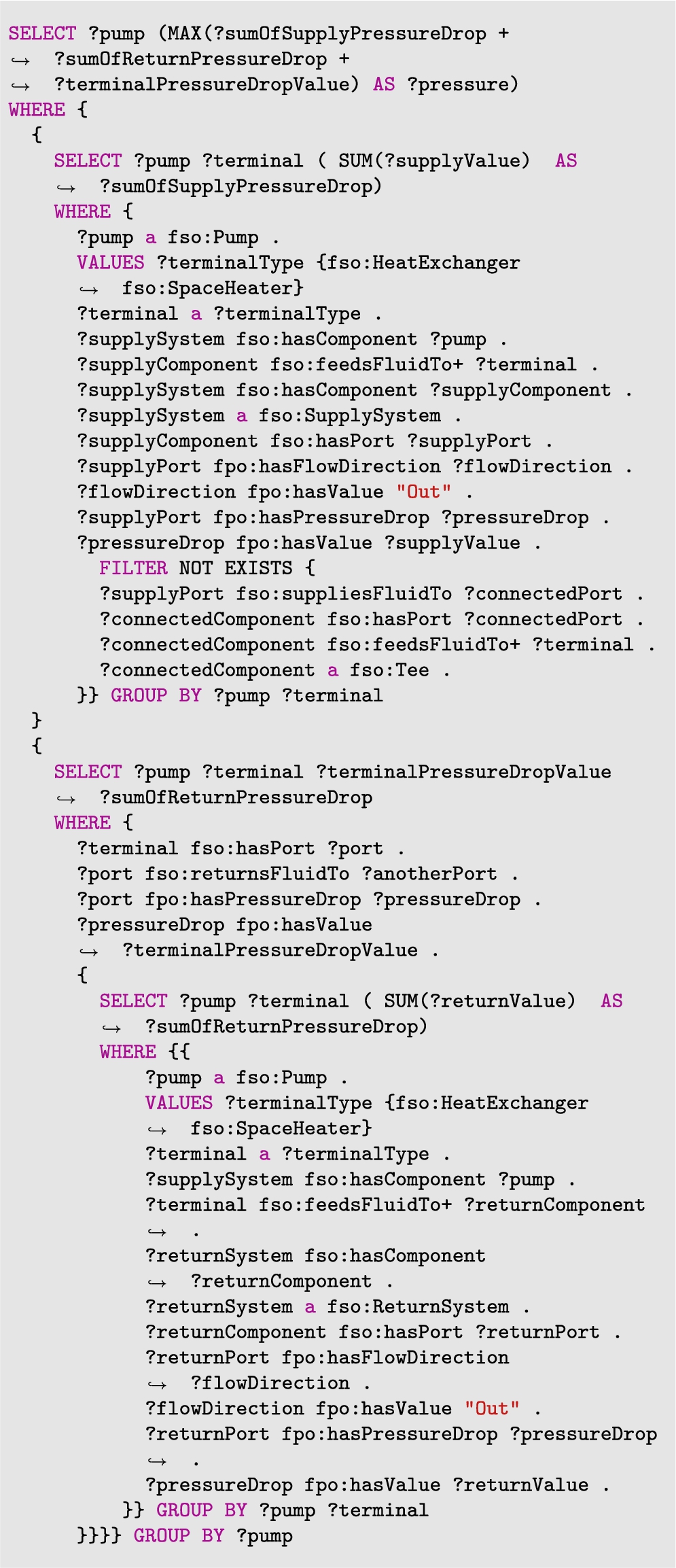
Appendix B.
Appendix B.Deleting systems, which don’t have any components
Listing 6.
A SPARQL update query to remove all fpo:SupplySystem and fpo:ReturnSystem, which is missing the predicate fso:hasComponent from the data model
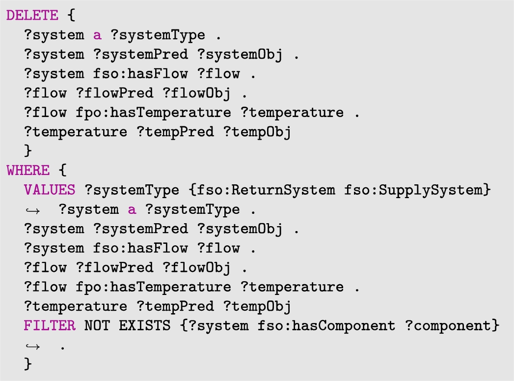
References
[1] | K. Afsari, C.M. Eastman and D. Castro-Lacouture, Javascript object notation (JSON) data serialization for IFC schema in web-based BIM data exchange, Automation in Construction 77: ((2017) ), 24–51, https://www.sciencedirect.com/science/article/pii/S0926580517300316. doi:10.1016/j.autcon.2017.01.011. |
[2] | Apache Jena Fuseki is a SPARQL server. https://github.com/apache/jena/blob/main/jena-fuseki2/apache-jena-fuseki/fuseki-server (accessed in 2022). |
[3] | ASHRAE, Ashrae’s BACnet Committee, Project Haystack and Brick Schema Collaborating to Provide Unified Data Semantic Modeling Solution, (2018) . https://www.ashrae.org/about/news/2018/ashrae-s-bacnet-committee-project-haystack-and-brick-/-schema-collaborating-to-provide-unified-data-semantic/--modeling-solution (accessed in 2022). |
[4] | B. Balaji, A. Bhattacharya, G. Fierro, J. Gao, J. Gluck, D. Hong, A. Johansen, J. Koh, J. Ploennigs, Y. Agarwal, M. Bergés, D. Culler, R.K. Gupta, M.B. Kjærgaard, M. Srivastava and K. Whitehouse, Brick: Metadata schema for portable smart building applications, Applied Energy 226: ((2018) ), 1273–1292. doi:10.1016/j.apenergy.2018.02.091. |
[5] | T.H. Beach, T. Kasim, H. Li, N. Nisbet and Y. Rezgui, Towards automated compliance checking in the construction industry, in: Database and Expert Systems Applications: 24th International Conference, DEXA 2013, Prague, Czech Republic, August 26–29, 2013, Proceedings, Part I, Vol. 24: , Springer, (2013) , pp. 366–380. |
[6] | J. Beetz, J. van Leeuwen and B. de Vries, Ifcowl: A case of transforming express schemas into ontologies, Artificial Intelligence for Engineering Design, Analysis and Manufacturing 23: (1) ((2009) ), 89–101. doi:10.1017/S0890060409000122. |
[7] | M. Bonduel, Towards a props ontology, (2018) , https://github.com/w3c-lbdcg/lbd/blob/gh-pages/presentations/props/presentationLBDcall20180312. |
[8] | T. Chipman, T. Liebich, M. Weise, T. Chipman and T. Liebich, Specification of a standardized format to define and exchange model view definitions with exchange requirements and validation rules, buildingsmart, CIBSE-Building Information Modelling ((2016) ). |
[9] | L. Daniele, F. den Hartog and J. Roes, Created in close interaction with the industry: The smart appliances reference (saref) ontology, in: Formal Ontologies Meet Industry, R. Cuel and R. Young, eds, Springer International Publishing, Cham, (2015) , pp. 100–112. doi:10.1007/978-3-319-21545-7_9. |
[10] | M. Debellis, A practical guide to building OWL ontologies using protégé 5.5 and plugins, (2021) . |
[11] | Description Logic Expressivity. http://protegeproject.github.io/protege/views/ontology-metrics/ (accessed in 2022). |
[12] | J. Dimyadi, C. Clifton, M. Spearpoint and R. Amor, Computerizing regulatory knowledge for building engineering design, Journal of Computing in Civil Engineering 30: (5) ((2016) ), C4016001. doi:10.1061/(ASCE)CP.1943-5487.0000572. |
[13] | J. Dimyadi, P. Pauwels and R. Amor, Modelling and accessing regulatory knowledge for computer-assisted compliance audit, Electronic Journal of Information Technology in Construction 21: ((2016) ), 317–336, Special issue CIB W78 2015 Special track on Compliance Checking. https://www.itcon.org/2016/21. |
[14] | A. Donkers, D. Yang, B. de Vries and N. Baken, Semantic web technologies for indoor environmental quality: A review and ontology design, Buildings 12: (10) ((2022) ), https://www.mdpi.com/2075-5309/12/10/1522. doi:10.3390/buildings12101522. |
[15] | C. Eastman, J. Lee, Y. Jeong and J. Lee, Automatic rule-based checking of building designs, (2009) , https://www.sciencedirect.com/science/article/pii/S0926580509001198. doi:10.1016/j.autcon.2009.07.002. |
[16] | I. Esnaola-Gonzalez and F. Díez, Integrating building and IOT data in demand response solutions, (2019) . |
[17] | Fast, unopinionated, minimalist web framework for node. https://github.com/expressjs/express (accessed in 2022). |
[18] | FastAPI is a modern, fast (high-performance), web framework for building APIs with Python 3.6+ based on standard Python type hints. https://github.com/tiangolo/fastapi (accessed in 2022). |
[19] | G. Governatori, M. Hashmi, H.-P. Lam, S. Villata and M. Palmirani, Semantic business process regulatory compliance checking using LegalRuleML, in: Knowledge Engineering and Knowledge Management, E. Blomqvist, P. Ciancarini, F. Poggi and F. Vitali, eds, Springer International Publishing, Cham, (2016) , pp. 746–761. doi:10.1007/978-3-319-49004-5_48. |
[20] | P. Hagedorn and M. König, Rule-based semantic validation for standardized linked building models, (2021) . doi:10.1007/978-3-030-51295-8_53. |
[21] | A.-H. Hamdan, M. Bonduel and R.J. Scherer, An ontological model for the representation of damage to constructions, (2019) . |
[22] | E. Hjelseth and N. Nisbet, Capturing normative constraints by use of the semantic mark-up rase methodology, in: Proceedings of CIB W78-W102 Conference, (2011) , pp. 1–10. |
[23] | A. Hogan, The Web of Data, (2020) . doi:10.1007/978-3-030-51580-5. |
[24] | A.S. Ismail, K.N. Ali and N.A. Iahad, A review on BIM-based automated code compliance checking system, in: 2017 International Conference on Research and Innovation in Information Systems (ICRIIS), (2017) , pp. 1–6. doi:10.1109/ICRIIS.2017.8002486. |
[25] | D.A. Koonce and R.P. Judd, A visual modelling language for express schema, International Journal of Computer Integrated Manufacturing 14: (5) ((2001) ), 457–472. doi:10.1080/09511920010022495. |
[26] | A.T. Kovacs and A. Micsik, BIM quality control based on requirement Linked Data, International Journal of Architectural Computing 19: (3) ((2021) ), 431–448. doi:10.1177/14780771211012175. |
[27] | V. Kukkonen, A. Kücükavci, M. Seidenschnur, M.H. Rasmussen, K.M. Smith and C.A. Hviid, An ontology to support flow system descriptions from design to operation of buildings, Automation in Construction 134: ((2022) ), 104067, https://www.sciencedirect.com/science/article/pii/S0926580521005185. doi:10.1016/j.autcon.2021.104067. |
[28] | G. Lee, J. Jeong, J. Won, C. Cho, S. You, S. Ham and H. Kang, Query performance of the IFC model server using an object-relational database approach and a traditional relational database approach, Journal of Computing in Civil Engineering 28: (2) ((2014) ), 210–222. doi:10.1061/(ASCE)CP.1943-5487.0000256. |
[29] | J. Lee and Y. Jeong, User-centric knowledge representations based on ontology for AEC design collaboration, Computer-Aided Design 44: (8) ((2012) ), 735–748, https://www.sciencedirect.com/science/article/pii/S0010448512000723. doi:10.1016/j.cad.2012.03.011. |
[30] | J.-K. Lee, C.M. Eastman and Y.C. Lee, Implementation of a BIM domain-specific language for the building environment rule and analysis, Journal of Intelligent & Robotic Systems 79: (3) ((2015) ), 507–522. doi:10.1007/s10846-014-0117-7. |
[31] | M. Lefrançois, J. Kalaoja, T. Ghariani, A. Zimmermann and T. Seas, D2. 2 SEAS Knowledge Model, Research Report, (2016) . |
[32] | S. Mehla and S. Jain, Rule languages for the Semantic Web, Vol. 755, (2019) . doi:10.1007/978-981-13-1951-8_73. |
[33] | M. Niknam and S. Karshenas, A shared ontology approach to semantic representation of BIM data, Automation in Construction 80: ((2017) ), 22–36, https://www.sciencedirect.com/science/article/pii/S0926580517302364. doi:10.1016/j.autcon.2017.03.013. |
[34] | Node.js is an open-source, cross-platform, JavaScript runtime environment. https://github.com/nodejs/node (accessed in 2022). |
[35] | J. Oraskari, M. Senthilvel and J. Beetz, SHACL is for LBD what mvdXML is for IFC, Vol. 78, (2021) , pp. 11–15. |
[36] | S. Park, Y.-C. Lee and J.-K. Lee, Definition of a domain-specific language for Korean building act sentences as an explicit computable form, Electronic Journal of Information Technology in Construction 21: ((2016) ). |
[37] | N. Pauen, D. Schlütter, J. Siwiecki, J. Frisch and C. Treeck, Integrated representation of building service systems: Topology extraction and tubes ontology, Bauphysik 42: ((2020) ), 299–305. doi:10.1002/bapi.202000027. |
[38] | P. Pauwels, Buildings and Semantics: Data Models and Web Technologies for the Built Environment, Buildings and Semantics, Taylor & Francis Group, (2022) . doi:10.1201/9781003204381. |
[39] | P. Pauwels, A. Costin and M.H. Rasmussen, Knowledge graphs and Linked Data for the built environment, Structural Integrity 20: ((2022) ), 157–183. doi:10.1007/978-3-030-82430-3_7. |
[40] | P. Pauwels, D. Van Deursen, R. Verstraeten, J. De Roo, R. De Meyer, R. Van de Walle and J. Van Campenhout, A semantic rule checking environment for building performance checking, Automation in Construction 20: (5) ((2011) ), 506–518, https://www.sciencedirect.com/science/article/pii/S0926580510001962. doi:10.1016/j.autcon.2010.11.017. |
[41] | P. Pauwels, S. Zhang and Y.-C. Lee, Semantic web technologies in aec industry: A literature overview, Automation in Construction 73: ((2017) ), 145–165, https://www.sciencedirect.com/science/article/pii/S0926580516302928. doi:10.1016/j.autcon.2016.10.003. |
[42] | M. Rasmussen, M. Lefrançois, G. Schneider and P. Pauwels, Bot: The building topology ontology of the w3c linked building data group, Semantic Web 12: (1) ((2020) ), 143–161. doi:10.3233/SW-200385. |
[43] | M.H. Rasmussen, M. Lefrançois, P. Pauwels, C.A. Hviid and J. Karlshøj, Managing interrelated project information in AEC knowledge graphs, Automation in Construction ((2019) ). doi:10.1016/j.autcon.2019.102956. |
[44] | M.H. Rasmussen, P. Pauwels, J. Karlshøj and C. Hviid, Proposing a central aec ontology that allows for domain specific extensions, Heraklion, Greece, (2017) , pp. 237–244, http://itc.scix.net/paper/lc3-2017-153. doi:10.24928/JC3-2017/0153. |
[45] | React, a JavaScript library for building user interfaces. https://github.com/reactjs/reactjs.org (accessed in 2022). |
[46] | R. Ren and J. Zhang, Model information checking to support interoperable BIM usage in structural analysis, (2019) , pp. 361–368. doi:10.1061/9780784482421.046. |
[47] | Revit: BIM software for designers, builders, and doers. https://www.autodesk.eu/products/revit (accessed in 2022). |
[48] | R. Sacks, C. Eastman, G. Lee and P. Teicholz, BIM Handbook: A Guide to Building Information Modeling for Owners, Designers, Engineers, Contractors, and Facility Managers, (2018) . |
[49] | K. Schwabe, J. Teizer and M. König, Applying rule-based model-checking to construction site layout planning tasks, Automation in Construction 97: ((2019) ), 205–219, https://www.sciencedirect.com/science/article/pii/S0926580517310208. doi:10.1016/j.autcon.2018.10.012. |
[50] | F. Seeberg and J. Tangeraas, Integration of Thermal Building Simulation Tools and Cloud-Based Building Information Models, (2022) . |
[51] | W. Solihin, J. Dimyadi, Y.-C. Lee, C. Eastman and R. Amor, The critical role of accessible data for BIM-based automated rule checking systems, in: Proceedings of the Joint Conference on Computing in Construction (JC3), Vol. 1: , (2017) , pp. 53–60. |
[52] | W. Solihin and C. Eastman, Classification of rules for automated BIM rule checking development, Automation in Construction 53: ((2015) ), 69–82, https://www.sciencedirect.com/science/article/pii/S0926580515000370. doi:10.1016/j.autcon.2015.03.003. |
[53] | W. Solihin and C.M. Eastman, A knowledge representation approach in BIM rule requirement analysis using the conceptual graph, Journal of Information Technology in Construction 21: ((2016) ), 370–401. |
[54] | W. Solihin, N. Shaikh, X. Rong and K. Lam, Beyond interoperatibility of building model: A case for code compliance checking, in: Proc., BPCAD Workshop, Carnegie Melon Univ., Pittsburgh, (2004) . |
[55] | R.K. Soman, M. Molina-Solana and J.K. Whyte, Linked-Data based Constraint-Checking (LDCC) to support look-ahead planning in construction, Automation in Construction 120: ((2020) ), 103369. doi:10.1016/j.autcon.2020.103369. |
[56] | S. Stolk and K. McGlinn, Validation of ifcOWL datasets using SHACL, Vol. 2636, (2020) . |
[57] | J. Tchouangouem, P. Pauwels, H. Fonbeyin, C. Magniont, M. Karray and B. Kamsu-Foguem, Integration of environmental data in BIM tool & linked building data, in: 7th International Workshop on Linked Data in Architecture and Construction, LDAC, 19-06-2019–21-06-2019, M. Poveda Villalon, P. Pauwels, R. De Klerk and A. Roxin, eds, Proceedings of the 7th Linked Data in Architecture and Construction Workshop, CEUR Workshop Proceedings, CEUR-WS.org, (2019) , pp. 78–91. http://linkedbuildingdata.net/ldac2019/. |
[58] | J.F. Tchouanguem Djuedja, F.H. Abanda, B. Kamsu-Foguem, P. Pauwels, C. Magniont and M.H. Karray, An integrated linked building data system: AEC industry case, Advances in Engineering Software 152: ((2021) ), 102930, https://www.sciencedirect.com/science/article/pii/S0965997820309765. doi:10.1016/j.advengsoft.2020.102930. |
[59] | W. Terkaj and A. Šojić, Ontology-based representation of IFC express rules: An enhancement of the ifcOWL ontology, Automation in Construction 57: ((2015) ), 188–201, https://www.sciencedirect.com/science/article/pii/S0926580515000886. doi:10.1016/j.autcon.2015.04.010. |
[60] | E. van den Bersselaar, J. Heinen, M. Chaudron and P. Pauwels, Automatic validation of technical requirements for a BIM model using Semantic Web technologies, in: 1st 4TU/14USA Research Day on Digitalization in the Built Environment, 01-04-2022, (2022) . |
[61] | W3C, A Semantic Web rule language combining OWL and RuleML, (2004) . https://www.w3.org/Submission/SWRL/. |
[62] | W3C, Notation3 (n3): A readable RDF syntax, (2011) . https://www.w3.org/TeamSubmission/n3/. |
[63] | W3C, Spin – overview and motivation, (2011) . https://www.w3.org/Submission/spin-overview/. |
[64] | W3C, Rif overview (second edition), (2013) . https://www.w3.org/TR/rif-overview/. |
[65] | W3C, Shapes constraint language (SHACL), (2017) . https://www.w3.org/TR/shacl/. |
[66] | W3C, SHACL and OWL compared, (2017) . https://spinrdf.org/shacl-and-owl.html. |
[67] | A. Wagner, W. Sprenger, C. Maurer, T.E. Kuhn and U. Rüppel, Building product ontology: Core ontology for linked building product data, Automation in Construction 133: ((2022) ), 103927, https://www.sciencedirect.com/science/article/pii/S0926580521003782. doi:10.1016/j.autcon.2021.103927. |
[68] | J. Werbrouck, M. Senthilvel, J. Beetz and P. Pauwels, Querying heterogeneous linked building data with context-expanded graphql queries, in: 7th International Workshop on Linked Data in Architecture and Construction, LDAC, 19-06-2019–21-06-2019, M. Poveda-Villalón, P. Pauwels, R. De Klerk and A. Roxin, eds, Proceedings of the 7th Linked Data in Architecture and Construction Workshop, CEUR Workshop Proceedings, CEUR-WS.org (2019) , pp. 21–34. http://linkedbuildingdata.net/ldac2019/. |


