
Modular ontology modeling
Abstract
Reusing ontologies for new purposes, or adapting them to new use-cases, is frequently difficult. In our experiences, we have found this to be the case for several reasons: (i) differing representational granularity in ontologies and in use-cases, (ii) lacking conceptual clarity in potentially reusable ontologies, (iii) lack and difficulty of adherence to good modeling principles, and (iv) a lack of reuse emphasis and process support available in ontology engineering tooling. In order to address these concerns, we have developed the Modular Ontology Modeling (MOMo) methodology, and its supporting tooling infrastructure, CoModIDE (the Comprehensive Modular Ontology IDE – “commodity”). MOMo builds on the established eXtreme Design methodology, and like it emphasizes modular development and design pattern reuse; but crucially adds the extensive use of graphical schema diagrams, and tooling that support them, as vehicles for knowledge elicitation from experts. In this paper, we present the MOMo workflow in detail, and describe several useful resources for executing it. In particular, we provide a thorough and rigorous evaluation of CoModIDE in its role of supporting the MOMo methodology’s graphical modeling paradigm. We find that CoModIDE significantly improves approachability of such a paradigm, and that it displays a high usability.
1.Introduction
Over the last two decades, ontologies have seen wide-spread use for a variety of purposes. Some of them, such as the Gene Ontology [16], have found significant use by third parties. However, the majority of ontologies have seen hardly any re-use outside the use cases for which they were originally designed [27,37].
It behooves us to ask why this is the case, in particular, since the heavy re-use of ontologies was part of the original conception for the Semantic Web field. Indeed, many use cases have high topic overlap, so that a re-use of ontologies on similar topics should, in principle, lower development cost. However, according to our experience, it is often much easier to develop a new ontology from scratch, than it is to try to re-use and adapt an existing ontology. We can observe that this sentiment is likely shared by many others, as the new development of an ontology so often seems to be preferred over adapting an existing one.
We posit, based on our experience, that four of the major issues preventing wide-spread re-use are (i) differing representational granularity, (ii) lack of conceptual clarity in many ontologies, (iii) lack and difficulty of adherence to established good modeling principles, and (iv) lack of re-use emphasis and process support in available ontology engineering tooling. We explain these aspects in more detail in the following. As a remedy for these issues, we propose tool-supported modularization, in a specific sense which we also explain in detail.
Representational granularity refers to modeling choices which determine the level of detail to be included in the ontology, and thus in the data (knowledge) graph. As an example, one model may simply refer to temperatures at specific space-time locations. Another model may also record an uncertainty interval. A third model may also record information about the measurement instrument, while a fourth may furthermore record calibration data for said instrument. Another example may be population figures for cities; the values are frequently estimated through the use of statistical models. That is, depending on the data and which statistical model was used, different figures would be calculated.
Note that a fine-grained ontology can be populated with coarse-granularity data; the converse is not true. If a use case requires fine-granularity data, a coarse-grained ontology is essentially useless. On the other hand, using a fine-grained ontology for a use case that requires only coarse granularity data is unwieldy due to (possibly massively) increased size of ontology and data graph.
Even more problematically, is that two use cases may differ in granularity in different ways in different parts of the data, respectively, ontology. That is, the level of abstraction is not uniform across the data. For example, one use case may call for details on the statistical models underlying population data, but not for measurement instruments for temperatures, whereas another use case may only need estimated population figures, but require calibration data for temperature measurements. Essentially, this means that attempting to re-use a traditional ontology may require modifying it in very different ways in different parts of the ontology. An additional complication is that ontologies are traditionally presented as monolithic entities and it is often hard to determine where exactly to apply such a change in granularity.
Conceptual clarity is a rather elusive concept that certainly has a strong subjective component. By this, we mean that an ontology should be designed and presented in such a way that it “makes sense” to domain experts, without too much difficulty. While presentation and documentation do play a major role, it is equally important to have intuitive naming conventions for ontological entities and, in particular, a structural organization (i.e., a schema for a data graph) which is meaningful for the domain expert.
We can briefly illustrate this using an example from the OAEI11 Conference benchmark ontologies [3,63]. One lists “author of paper” and “author of student paper” as two distinct subclasses of “person.” This raises the question: why is “author of student paper” not a subclass of “author of paper” (apart from subclassing both as “person” which we will discuss in the next paragraph). In another ontology in this collection, “author” is a subclass of “user”, and “author” itself has exactly two subclasses: “author, who is not a reviewer” and “co-author” – which is hardly intuitive.
By definition, an ontology with high conceptual clarity will be much easier to re-use, simply because it is much easier to understand the ontology in the first place. Thus, a key quest for ontology research is to develop ontology modeling methodologies which make it easier to produce ontologies with high conceptual clarity.
That following already established good modeling principles makes an ontology easier to understand and re-use, should go without saying. However, good modeling principles are not simply a checklist that can easily be followed. Even simple cases, such as the recommendation to not have perdurants and endurants22 together in subclass relationships (in the example above, author should not be a subclass of person; rather, authorship is a role of the person) are commonly not followed in existing ontologies. At the current stage of research, “good modeling” appears to largely be a function of modeling experience and more of an art, than a science, which has not been condensed well enough into tangible insights that can easily be written up in a tutorial or textbook.
A further issue is that even in cases where the aforementioned re-use challenges are manageable, implementing and subsequently maintaining re-use in practice is problematic due to limited support for re-use in available tooling. Once a reusable ontology resource has been located, a suitable reuse method must first be selected; e.g., cloning the entire design into the target ontology/namespace, using owl:imports to include the entire source ontology as-is, cloning individual definitions, locally subsuming or aligning to remote ontology entities, etc. The authors have previously contributed methodological guidance supporting developers in selecting an appropriate reuse method based on the modeling context [23, 177–184]; but without comprehensive tooling support, carrying out such reuse in practice (especially when several resources are re-used) is still time-consuming and error-prone.
Furthermore, through ontology re-use, the ontologist commits to a design and logic built by a third party. As the resulting ontology evolves, keeping track of the provenance of re-used ontological resources and their locally instantiated representations may become important, e.g., to resolve design conflicts resulting from differing requirements, or to keep up-to-date with the evolution of the re-used ontology. This is particularly important in case remote resources are reused directly rather than through cloning into a local representation (e.g., using owl:imports or through alignments to remote entities using subclass or equivalence relations); in those cases remote changes could, unbeknownst to the developer, cause their ontology to become inconsistent. Such state-keeping is decidedly non-trivial without appropriate tool support.
Processes and tools should be sought that make it possible to leverage modeling experience by seasoned experts, without actually requiring their direct involvement. This was one of the original ideas behind ontology re-use which, unfortunately, did not quite work out that well, for reasons including those mentioned above. Our modularization approach, however, together with the systematic utilization of ontology design patterns, and our accompanying tools, gives us a means to address this issue.
The notion of module has taken on a variety of meanings in the Semantic Web community [2,18,60]. For our purposes, a module is a part of the ontology (i.e., a subset of the ontology axioms) which captures a key notion together with its key attributes. For example, an event module may contain, other than an Event class, also relations and classes designed for the representation of the event’s place, time, and participants. On the other hand, a simple module for a cooking process may encompass relations and classes for recording ingredients and their amounts, time and equipment required, and so on. A module is thus as much a technical entity, in the sense of a defined part of an ontology, as well as a conceptual entity, in the sense that it should encompass different classes (and relationships between them) which “naturally” (from the perspective of domain experts) belong together. Modules may overlap. They may be nested. They provide an organization of an ontology as an interconnected collection of modules, each of which resonates with the corresponding part of domain conceptualization by the experts.
Note that modules, in this sense, indicate a departure from a more traditional perspective on ontologies, where they are often viewed as enhanced taxonomies, with a strong emphasis on the structure of the class subsumption hierarchy. Modules can contain their own taxonomy structure, guided by the design logic of the module, that ideally integrates into usability-wise coherent taxonomy of the ontology as a whole; but the latter is not a hard requirement. From our perspective, the occurrence of subclass relationships within an ontology is not a key guiding principle for modeling or ontology organization. As we will see, modules make it possible to approach ontology modeling in a divide-and-conquer fashion; first, by modeling one module at a time, and then connecting them.33
Modules furthermore provide an easy way of avoiding the hassle of dealing with ontologies that are large and monolithic: understanding an ontology amounts to understanding each of its modules, and then their interconnections. This, at the same time, provides a recipe for documentation which resonates with domain experts’ conceptualizations (which were captured by means of the modules), and thus makes the documentation and ontology easier to understand. Additionally, using modules facilitates modification, and thus adapting an ontology to a new purpose, as a module is much more easily replaced by a new module with, for instance, higher granularity, because the module inherently identifies where changes should be localized.
The systematic use of ontology design patterns [8,17] is another central aspect of our approach, as many of their promises resonate with the issues that our approach is addressing [28]. An ontology design pattern is a generic solution to a recurring ontology modeling problem. To give an example, a “Trajectory” pattern would be a partial ontology that can be used to record “trajectories,” such as the route of a ship or piece of cargo. If well-designed, this pattern may, with only minor and easy modifications, be suitable to be used as a template for trajectory modules within many ontologies. It must be noted that patterns are not one-size-fits-all solutions. For example, the Trajectory pattern from [31], which we have found to be highly versatile, assumes a discretized recording of a trajectory (as a time-sequence of locations), however it would not account for recording of a trajectory as, say, a set of equations.
In our approach, well-designed ontology design patterns, provided as templates to the ontology modelers, make it easier to follow already established good modeling principles, as the patterns themselves will already reflect them [24]. When a module is to be modeled, within our process there will always be a check whether some already existing ontology design pattern is suitable to be adapted for the purpose. Modules, as such, are often derived from patterns as templates.
The principles and key aspects laid out above are tied together in a clearly defined modular ontology modeling process which is laid out below, and which is a refinement – with some changes of emphasis – of the eXtreme Design methodology [6]. It is furthermore supported by a set of tools developed for support of this process, the CoModIDE plug-in to Protégé, and which we will discuss in detail below. Also central to our approach is that it is usually a collaborative process with a (small) team that jointly has the required domain, data and ontology engineering expertise, and that the actual modeling work utilizes schema diagrams as the central artifact for modeling, discussion, and documentation.
This paper is structured as follows. Section 2 describes our related work – this covers precursor methods, the eXtreme Design methodology, and overviews of concepts fundamental to our approach. Section 3 describes our modular ontology modeling process in detail. Section 4 presents CoModIDE as a tool for supporting the development of modular ontologies through a graphical modeling paradigm, as well as a rigorous evaluation of its effectiveness and usability. Section 5 describes additional, supporting infrastructure and other resources for the MOMo process. Finally, in Section 6, we conclude.
This paper significantly extends [51] and summarizes several other workshop and conference papers: [50,53], and [52].
2.Related work
2.1.Ontology engineering methods
The ideas underpinning the Modular Ontology Modeling methodology build on years of prior ontology engineering research, covering organizational, process, and technological concerns that impact the quality of an ontology development process and its results.
The METHONTOLOGY methodology is presented by Férnandez et al. in [15]. It is one of the earlier attempts to develop a development method specifically for ontology engineering processes (prior methods often include ontology engineering as a sub-discipline within knowledge management, conflating the ontology-specific issues with other more general types of issues). Férnandez et al. suggest, based largely on the authors’ own experiences of ontology engineering, an ontology lifecycle consisting of six sequential work phases or stages: Specification, Conceptualisation, Formalisation, Integration, Implementation, and Maintenance. Supporting these stages are a set of support activities: Planification, Acquiring knowledge, Documenting, and Evaluating.
The On-To-Knowledge Methodology (OTKM) [61] is, similarly to METHONTOLOGY, a methodology for ontology engineering that covers the big steps, but leaves out the detailed specifics. OTKM is framed as covering both ontology engineering and a larger perspective on knowledge management and knowledge processes, but it heavily emphasises the ontology development activities and tasks (in [61] denoted the Knowledge Meta Process). OTKM emphasises initial collaboration between domain experts and ontology engineers in the Kick-off phase. In the subsequent Refinement phase an ontology engineer formalises the initial semi-formal model into a real ontology on their own, without aid of a domain expert. In subsequent Evaluation, both technical and user-focused aspects of the knowledge based system in which the ontology is used, are evaluated. Finally, the Application and Evolution phase concerns the deployment of said knowledge based system, and the organisational challenges associated with maintenance responsibilities.
DILIGENT, by Pinto et al. [43], is an abbreviation for Distributed, Loosely-Controlled and Evolving Engineering of Ontologies, and is a method aimed at guiding ontology engineering processes in a distributed Semantic Web setting. The method emphasises decentralised work processes and ontology usage, domain expert involvement, and ontology evolution management. This distributed development process is formalised into five activities: build, local adaptation, analysis, revision, and local update. The authors show how Rhetorical Structure Theory [40] can be used as a framework to constrain design discussions in a distributed ontology engineering setting, guiding the design process.
In all three of these well-established methods, the process steps that are defined are rather coarse-grained. They give guidance on overall activities that need to be performed in constructing an ontology, but more fine-grained guidance (e.g., how to solve common modeling problems, how to represent particular designs on concept or axiom level, or how to work around limitations in the representation language) is not included. It is instead assumed that the reader is familiar with such specifics of constructing an ontology. This lack of guidance arguably is a contributor to the three issues preventing re-use, discussed in Section 1.
2.2.Ontology design patterns
Ontology Design Patterns (ODPs) were introduced at around the same time independently by Gangemi [17] and Blomqvist and Sandkuhl [8], as potential solutions to the drawbacks of classic methods described above. The former defines such patterns by way of the characteristics that they display, including examples such as “[an ODP] is a template to represent, and possibly solve, a modelling problem” [17, p. 267] and “[an ODP] can/should be used to describe a ‘best practice’ of modelling” [17, p. 268]. The latter describes ODPs as generic descriptions of recurring constructs in ontologies, which can be used to construct components or modules of an ontology. Both approaches emphasise that patterns, in order to be easily reusable, need to include not only textual descriptions of the modelling issue or best practice, but also some formal ontology language encoding of the proposed solution. The documentation portion of the pattern should be structured and contain those fields or slots that are required for finding and using the pattern.
A substantial body of work has been developed based on this idea, by a sizable distributed research community.44 Key contributions include the eXtreme Design methodology (detailed in Section 2.3) and several other pattern-based ontology engineering methods (Section 2.4). The majority of work on ODPs has been based on the use of miniature OWL ontologies as the formal pattern encoding, but there are several examples of other encodings, the most prominent of which are OPPL [14] and more recently OTTR [59].
MOMo extends on those methods, but also incorporates results from our past work on how to document ODPs [26,29,32], how to implement ODP support tooling [22] and how to instantiate patterns into modules by “stamping out copies” [24].
2.3.eXtreme design
The eXtreme Design (XD) methodology [6] was originally proposed as a reaction to previous waterfall-oriented methods (e.g., some of those discussed above). XD instead borrows from agile software engineering methods, emphasizing a divide-and-conquer approach to problem-solving, early or continuous deployment rather than a “one-shot” process, and early and frequent refactoring as the ontology grows. Crucially, XD is built on reusing of ontological best practices via ODPs.
![eXtreme Design method overview, from [6].](https://content.iospress.com:443/media/sw/2023/14-3/sw-14-3-sw222886/sw-14-sw222886-g001.jpg)
The XD method consists of a number of tasks, as illustrated in Fig. 1. The first two tasks deal with establishing a project context (i.e., introducing initial terminology and obtaining an overview of the problem) and collecting initial requirements in the form of a prioritized list of user stories (describing the required functionality in layman’s terms). These steps are performed by the whole XD team together with the customer, who is familiar with the domain and who understands the required functionalities of the resulting ontology. The later steps of the process are performed in pairs of two developers (these steps are in the figure enclosed in the large box). They begin by selecting the top prioritised user story that has not yet been handled, and transform that story into a set of requirements in the form of competency questions (data queries), contextual statements (invariants), and reasoning requirements. Customer involvement at this stage is required to ensure that the user story has been properly understood and that the elicited requirements are correctly understood.
The development pair then selects one or a small set of interdependent competency questions for modelling. They attempt to match these against a known ODP, possibly from a designated ODP library. The ODP is adapted and integrated into the ontology module under development (or, if this iteration covers the first requirements associated with a given user story, a new module is created from it). The module is tested against the selected requirements to ensure that it covers them properly. If that is the case, then the next set of requirements from the same user story is selected, a pattern is found, adapted, and integrated, and so on. Once all requirements associated with one user story have been handled, the module is released by the pair and integrated with the ontology developed by the other pairs in the development team. The integration may be performed either by the development pair themselves, or by a specifically designated integration pair.
XD has been evaluated experimentally and observationally, with results indicating that the method contributes to reduced error rates in ontologies [5,7], increased coverage of project requirements [5], and that pattern usage is perceived as useful and helpful by inexperienced users [5,7,20]. However, results also indicate that there are pitfalls associated with a possibility of over-dependence on ODP designs, as noted in [20].
2.4.Other pattern-based methods
SAMOD [42], or Simplified Agile Methodology for Ontology Development, is a recently developed methodology that builds on and borrows from test-driven and agile methods (in particular eXtreme Design). SAMOD emphasises the use of tests to confirm that the developed ontology is consistent with requirements, and prescribes that the developer construct three types of such tests: model tests, data tests, and query tests. The method prescribes a light-weight three-step process broadly mirroring XD, i.e., consisting of (1) constructing an ontology module as a partial solution to the development scenario (including tests), (2) merging that new module into the main branch ontology, (3) refactoring as needed. After each of these steps, all the tests defined for the module and/or main branch ontology are executed, and development is halted until all tests are passed.
Hammar [23] presents a set of proposed improvements to the XD methodology under the umbrella label “XD 1.1”. These include (1) a set of roles and role-specific responsibilities in an XD project, (2) suggestions on how to select and implement other forms of ontology re-use in XD than just patterns (e.g., import, remote references, slicing, partial cloning), and (3) a project adaptation questionnaire supporting XD projects in adapting the process to their particular development context (e.g., team cohesion, distribution, skill level, domain knowledge, etc).
XD, SAMOD, and XD 1.1 emphasize the needs for suitable support tooling for, e.g., finding suitable ODPs, instantiating those ODPs into an ontology, and executing tests across the ontology or parts of it. In developing MOMo and the CoModIDE platform, we propose and develop solutions to two additional support tooling needs: that of intuitive and accessible graphical modeling, and that of a curated high-quality pattern library.
2.5.Graphical conceptual modelling
[19] proposes three factors (see Fig. 2) that influence the construction of a conceptual model, such as an ontology; namely, the person doing the modeling (both their experience and know-how, and their interpretation of the world, of the modeling task, and of model quality in general), the modeling grammar (primarily its expressive power/completeness and its clarity), and the modeling process (including both initial conceptualisation and subsequent formal model-making). Crucially, only the latter two factors can feasibly be controlled in academic studies. Research in this space tends to focus on one or the other of these factors, i.e., studying the characteristics of a modeling language or a modeling process. Our work on CoModIDE straddles this divide: employing graphical modeling techniques reduces the grammar available from standard OWL to those fragments of OWL that can be represented intuitively in graphical format; employing design patterns affects the modeling process.
![Factors affecting conceptual modeling, from [19].](https://content.iospress.com:443/media/sw/2023/14-3/sw-14-3-sw222886/sw-14-sw222886-g002.jpg)
Graphical conceptual modeling approaches have been extensively explored and evaluated in fields such as database modeling, software engineering, business process modeling, etc. Studying model grammar, [58] compares EER notation with an early UML-like notation from a comprehensibility point-of-view. This work observes that restrictions are easier to understand in a notation where they are displayed coupled to the types they apply to, rather than the relations they range over. [10] proposes a quality model for EER diagrams that can also extend to UML. Some of the quality criteria in this model, that are relevant in graphical modeling of OWL ontologies, include minimality (i.e., avoiding duplication of elements), expressiveness (i.e., displaying all of the required elements), and simplicity (displaying no more than the required elements).
[1] studies the usability of UML, and reports that users perceive UML class diagrams (closest in intended use to ontology visualizations) to be less easy-to-use than other types of UML diagrams; in particular, relationship multiplicities (i.e., cardinalities) are considered frustrating by several subjects. UML displays such multiplicities by numeric notation on the end of connecting lines between classes. [36] analyses UML and argues that while it is a useful tool in a design phase, it is overly complex and as a consequence, suffers from redundancies, overlaps, and breaks in uniformity. [36] also cautions against using difficult-to-read and -interpret adornments on graphical models, as UML allows.
Various approaches have been developed for presenting ontologies visually and enabling their development through a graphical modeling interface, the most prominent of which is probably VOWL, the Visual Notation for OWL Ontologies [39], and its implementation viewer/editor WebVOWL [38,62]. VOWL employs a force-directed graph layout (reducing the number of crossing lines, increasing legibility) and explicitly focuses on usability for users less familiar with ontologies. As a consequence of this, VOWL renders certain structures in a way that, while not formally consistent with the underlying semantics, supports comprehensibility; for instance, datatype nodes and owl:Thing nodes are duplicated across the canvas, so that the model does not implode into a tight cluster around such often used nodes. It has been evaluated over several user studies with users ranging from laymen to more experienced ontologists, with results indicating good comprehensibility. CoModIDE has taken influence from VOWL, e.g., in how we render datatype nodes. However, in a collaborative editing environment in which the graphical layout of nodes and edges needs to remain consistent for all users, and relatively stable over time, we find the force-directed graph structure (which changes continuously as entities are added/removed) to be unsuitable.
For such collaborative modeling use cases, the commercial offering Grafo55 offers a very attractive feature set, combining the usability of a VOWL-like notation with stable positioning, and collaborative editing features. Crucially, however, Grafo does not support pattern-based modular modeling or import statements, and only supports RDFS semantics, and as a web-hosted service, does not allow for customizations or plugins that would support such a modeling paradigm.
CoModIDE is partially based on the Protégé plugin OWLAx, as presented in [47]. OWLAx plugin supports one-way translation from graphical schema diagrams drawn by the user, into OWL ontology classes and properties; however, it does not render such constructs back into a graphical form. There is thus no way of continually maintaining and developing an ontology using only OWLAx. There is also no support for design pattern re-use in this tool.
3.The modular ontology modeling methodology
Modular Ontology Modeling (MOMo66) consists of a well-defined process, together with the utilization of specific components that support the process. The design characteristics of MOMo and CoModIDE provide the following benefits over the prior options introduced in Sections 2.3 and 2.4:
Module focus – While earlier approaches may recommend the instantiation of ODPs into the target ontology, they typically do not emphasize the self-containedness of those instantiations; instead, ODPs are often merged into larger blocks of functionality or entirely monolithic ontologies. In MOMo, by contrast, instantiating and interlinking small self-contained modules is a defining characteristic, that provides several benefits; e.g., maintainability is simplified since each module can be modified with minimal impact on the ontology as a whole; and the provenance of each part of the ontology, back to the original requirements, can easily be maintained in module documentation or metadata.
A curated ODP library – Methodologies based on ODP usage tend to assume the existence of suitable patterns. While the ODP community continues to develop and publish patterns through, e.g., the ontologydesignpatterns.org portal, those patterns vary in terms of documentation quality and completeness, foundational semantics, granularity, specificity or abstraction, etc. In practice, this makes consistent ODP usage in non-trivially sized projects difficult. MOMo instead suggests the use of an internally consistent library of patterns (see Section 3.4); either a well-curated public library with general coverage, or one developed specifically for the project/domain at hand.
Diagram-first modeling – Where other methodologies might recommend the use of illustrations as a way of explicating ODP design, and suggest the use of post-facto ontology documentation for communication and other purposes, in MOMo the developed schema diagrams and their accompanying human-readable documentation are themselves first-order deliverables of the ontology engineering process; their (manual) translation into OWL is a final step of post-processing. The use of such more accessible formalisms enables non-ontology-experts to easily participate in development of and quality assurance over the developed modules and ontologies; not only as requirements sources and passive observers, but as active participants. Furthermore, since the diagrams and their documentation are ontology language-agnostic, they can be translated into other formalisms than OWL, should the need arise, by a developer with no or limited OWL expertise.
In this part of the paper, we lay out the key components, namely schema diagrams, our approach to OWL axiomatization, ontology design patterns, and the concept of modules already mentioned previously, as well as the process which ties them together. In Section 4 and 5, we discuss our supporting tools and infrastructure, however they should be considered just one possible instantiation of the more general MOMo methodology. Indeed, most of the first part of the MOMo process is, in our experience, best done in analog mode, armed with whiteboards, flip-charts and a suitable modeling team.
3.1.The modeling team
Team composition is of critical importance for establishing a versatile modular ontology. Different perspectives are very helpful, as long as the group does not lose focus. Arrival at a consensus model between all parties which constitutes a synthesis of different perspectives is key, and such a consensus is much more likely to be suitable to accommodate future use cases and modifications. It is therefore advisable to have more than one domain expert with overlapping expertise, and more than one ontology engineer on the team. Based on our experiences, three types of participants are needed in order to have a team that can establish a modular ontology: domain experts, ontology engineers, and data scientists. Of course some people may be able to fill more than one role. An overall team size of 6–12 people appears to be ideal, based on our experiences (noted in Section 5.5). Meetings with the whole team will be required, but in the MOMo process most of the work will fall on the ontology engineers between the meetings.
1. The domain experts should primarily bring a deep knowledge of the relevant subject area(s) and of the use case scenario(s). Ideally, they should also be aware of perspectives taken by other domain experts in order to avoid overspecialization of the model.
2. The ontology engineers should be familiar with the MOMo process, supporting tools, and relevant standards (in particular, OWL), and guide the meetings. Their role is to capture the discussions, resulting in (draft) schema diagrams which are then further discussed and refined by the team. Between team meetings, they will also work out detailed documentation of what has been discussed, which, in turn, will be used as prompts in following modeling sessions. At least one of the ontology engineers should have a deep understanding of the logical underpinnings of OWL.
3. The data scientists should bring a detailed understanding of the actual data that is relevant to the use case(s) and will or may be utilized (e.g., integrated by means of the ontology as overarching schema). Their role is to make sure that the model does not deviate in an incompatible way from the actual data that is available.
3.2.Schema diagrams
Schema diagrams are a primary tool of the MOMo process. In particular, they are the visual vehicle used to coalesce team discussions into a draft model and used centrally in the documentation. This diagram-based approach is also reflected in our tools, which we will present in Sections 4–5.
Let us first explain what we do – and do not – mean by schema diagram, and we use Fig. 3 as an example,77 which depicts the Provenance module from the Enslaved Ontology [54].
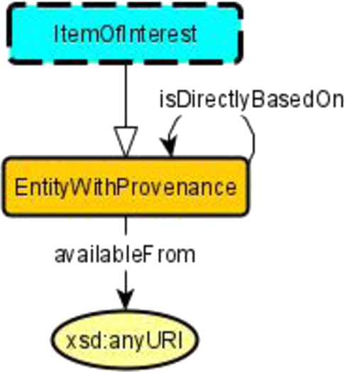
Our schema diagrams are labeled graphs that indicate OWL entities and their (possible) relationships. Nodes can be labeled by (1) classes (EntityWithProvenance – rectangular, orange, solid border), (2) modules (Agent, PersonRecord, ProvenanceActivity – rectangular, light blue, dashed border), (3) controlled vocabularies (DocumentTypes, LicenseInformation – rectangular, purple, solid border), (4) datatypes (xsd:string, xsd:anyURI – oval, yellow, solid border). Arrows can be white-headed without label, indicating a subclass relationship (the arrow between PersonRecord and EntityWithProvenance) or can be labeled with the name of the property, which could be a data or an object property, which is identified by the target of the arrow, which may be a datatype.
Fig. 3.
Schema diagram for the Provenance module from the Enslaved Ontology [54]. It is based on the Provenance pattern from [53], which in turn is based on the core of PROV-O [44].
![Schema diagram for the Provenance module from the Enslaved Ontology [54]. It is based on the Provenance pattern from [53], which in turn is based on the core of PROV-O [44].](https://content.iospress.com:443/media/sw/2023/14-3/sw-14-3-sw222886/sw-14-sw222886-g003.jpg)
Indication of a module in a diagram means that instead of the node (the light blue, dashed border), there may be a complex model in its very own right, which would be discussed, depicted, and documented separately. For example, PersonRecord in the Enslaved Ontology is a complex module with several sub-modules. The diagram in Fig. 3 “collapses” this into a single node, in order to emphasize what is essential for the Provenance module. Controlled vocabularies are predefined sets of IRIs with a specific meaning that is documented externally (i.e., not captured in the ontology itself). A typical example would be IRIs for physical units like meter or gram or, as in our example diagram, IRIs for specific copyright licences, such as CC-BY-SA. Datatypes would be the concrete datatypes allowed in OWL. This type of schema diagram underlies a study on automatic schema diagram creation from OWL files [50].
Note that our schema diagrams do not directly indicate what the underlying OWL axioms are. A (labeled) arrow only indicates that a property could typically be used between nodes of the indicated types. It does not indicate any of functionality, existential or universal restriction, etc. It also does not indicate any specific domain or range axioms or use of logical connectives, such as conjunction or disjunction. In the end, the ontology will consist of a set of OWL axioms (i.e., a concrete axiomatization will be done), but these are created rather late in the process. During team modeling, simple diagrams help to focus on the essentials and are intuitively accessible even for participants with no background in ontology engineering. The ontology engineers, however, should keep in mind that logical axioms are needed eventually and that the diagrams alone remain highly ambiguous.
3.3.OWL axioms
As already mentioned, OWL axioms are the key constituents of an ontology as a data artifact, although in our experience quality documentation is of at least the same importance. As has been laid out elsewhere [30], axiomatizations can have different interpretations, and while they can, for example, be used for performing deductive reasoning, this is not their main role as part of the MOMo approach. Rather, for our purposes axioms serve to disambiguate meaning, for a human user of the ontology. As such, they can also be understood as a way to disambiguate the schema diagram, as appropriate (e.g., by labeling a property functional, by declaring domain and range restrictions).
As such, we recommend a rather complete axiomatization, as long as it does not force an overly specific reading on the ontology. We usually use the checklist from the OWLAx tool [47] to axiomatize with simple axioms. More complex axioms, in particular those that span more than two nodes in a diagram, can be added conventionally or by means of the ROWLTab Protégé plug-in [45,46]. We also utilize what we call structural tautologies which are axioms that are in fact tautologies such as
3.4.Ontology design patterns
As already mentioned, Ontology Design Patterns (ODPs) have originated in the early 2000s as reusable solutions to frequently occurring ontology design problems. Most ODPs can currently be found on the ontologydesignpatterns.org portal, and they appear to be of very varied quality both in terms of their design and documentation, and following a variety of different design principles. While they proved to be useful for the community [28], as part of MOMo, we re-imagine ontology design patterns and their use.
Most importantly, rather than working with a crowd-sourced collection of ODPs, there seems to be a significant advantage in working with a well-curated library of ontology design patterns that are developed with a similar mindset, and expressed and documented in a uniform way. A first version of such a library is the Modular Ontology Design Library (MODL) [53], which contains patterns that we have frequently found to be useful in the recent past. We furthermore utilize the Ontology Pattern Language (OPLa) [26,29] which is an annotation language using OWL that makes it possible to work with ODPs (and modules) in a programmatic way.
![Schema diagram of the MODL Provenance ODP. It is based on the core of PROV-O [44].](https://content.iospress.com:443/media/sw/2023/14-3/sw-14-3-sw222886/sw-14-sw222886-g004.jpg)
As an example, a schema diagram for the MODL Provenance pattern is provided in Fig. 4. In MOMo, the pattern would be used as a template in the sense that it serves as a blueprint, usually for a module – such as the Provenance module depicted in Fig. 3 in the resulting ontology. That is, the pattern can be modified, simplified, extended at will, but usually both the schema diagram and the axioms of the ODP will still be reflected and in some way recognizable in the module. The resulting ontology will also use OPLa to capture the information that the resulting module has re-used an ODP as a template.
3.5.Modules
An (ontology) module is a part of an ontology which captures a key notion, and its key relations to other notions. An example that was already discussed is given in Fig. 3. A module may sometimes consist of a central class together with relations (properties) to other classes, modules, controlled vocabularies or datatypes, but can sometimes also be of a more complex structure.
Modules can be overlapping, or nested. While they are often based on some shared semantics, as encoded in an ODP, this is not a hard requirement; the purpose of the module is to encapsulate a set of interrelated functionality, the logic of which classes and properties that the module covers can be, and often is, guided, not only by the semantics of the domain, but also by the development context and use case. For example, in the context of Fig. 3, the PersonRecord class could reasonably be considered to be outside the module. Likewise, the EntityWithProvenance class may or may not be considered part of the PersonRecord module. The latter may depend on the question how “central” provenance for person records is, in the application context of the ontology. In this sense, ontology modules are ambiguous in their delineation, just as the human concepts they are based on.
Fig. 5.
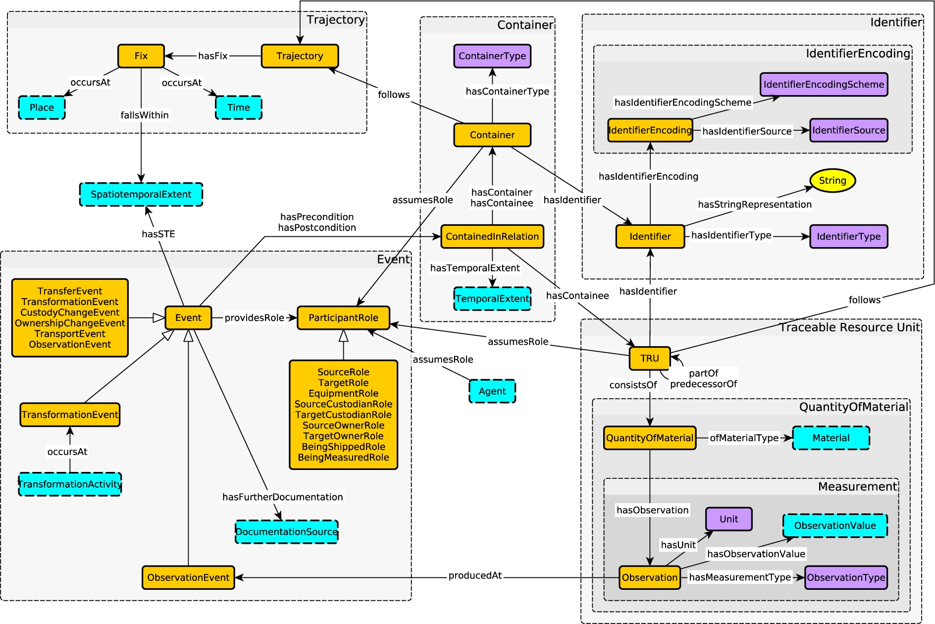
Schema diagram of a supply chain ontology currently under development by the authors.
As a data artifact, though, i.e., in the OWL file of the ontology, we will use the above-mentioned Ontology Pattern Language OPLa to identify modules, i.e. the ontology engineers will have to make an assessment how to delineate each module in this case. OPLa will furthermore be used to identify ODPs (if any) which were used as templates for a module.
Finally, an ontology’s modules will drive the documentation, which will usually discuss each module in turn, with separate schema diagrams, axioms, examples and explanations, and will only at the very end discuss the overall ontology which is essentially a composition of the modules. In a diagram that encompasses several modules, the modules can be identified visually using frames or boxes around sets of nodes and arrows. An example for this is given in Fig. 5. Several modules are identified by grey boxes in this diagram, including nested modules such as on the lower right.
3.6.The MOMo workflow
We now describe the Modular Ontology Modeling workflow that we have been applying and refining over the past few years. It borrows significantly from the eXtreme Design approach described in Section 2.3, but has an emphasis on modularization, systematic use of schema diagrams, and late-stage OWL generation. Table 1 summarizes the steps of the workflow, and the following sections discuss each step in more detail. A walk-through tutorial for the approach can be found in [56].
Table 1
MOMo workflow
| Step | Responsible | Output |
| 1. Describe use cases & data sources | Entire team | Use case descriptions |
| 2. Gather competency questions | Entire team | List of CQs |
| 3. Identify key notions | Entire team | List of key notions |
| 4. Identify existing ODPs | Ontology engineers | Selected ODP(s) for each key notion. |
| 5. Create module diagrams | Entire team | Diagrammatic representation of the solution module. |
| 6. Document modules & axioms | Ontology engineers & domain experts | Module documentation with embedded schema diagrams, axiomatization, etc. (e.g., in LaTeX, Word, HTML format). |
| 7. Create ontology diagram | Ontology engineers | Diagrammatic representation of the whole composed ontology. |
| 8. Add spanning axioms | Ontology engineers | Documentation of the entire ontology with embedded schema diagrams, axiomatization, etc. (e.g., in LaTeX, Word, HTML format). |
| 9. Review naming & axioms | Ontology engineers | Updated module and ontology documentation. |
| 10. Create OWL file & axioms | Ontology engineers | An OWL file for publication and use. |
This workflow is not necessarily a strict sequence, and work on later steps may cause reverting to an earlier step for modifications. Sometimes subsequent steps are done together, e.g., 4 and 5, or 7 and 8.
Steps 1 through 4 can usually be done through a few shorter one-hour teleconferences (or meetings), the number of which depends a lot on the group dynamics and prior experience of the participants. This sequence would usually also include a brief tutorial on the modeling process. If some of the participants already have a rather clear conception of the use cases and data sources, then 2 or 3 one-hour calls would often suffice.
In our experience, synchronous engagement (in the sense of longer meetings) of the modeling team usually cannot be avoided for step 5. Ideally, they would be conducted through in-person meetings, which for efficiency should usually be set up for 2 to 3 subsequent days. Online meetings can also be almost as effective, but for this we recommend several, at least 3, subsequent half-day sessions about 4–5 hours in length.
Steps 6 to 10 are mostly up to the ontology engineers at the team, however they would request feedback and correctness checks from the data and domain experts. This can be done asynchronously, but depending on preference could also include some brief teleconferences (or meetings).
3.6.1.Describe use cases and gather possible data sources
As the first step, the use case, i.e., the problem to be addressed, should be described. The output description can be very brief, e.g., a paragraph of text, and it does not necessarily have to be very crisp. In fact it may describe a set of related use cases rather than one specific use case, and it may include future extensions which are currently out of scope. Setting up a use case description in this way alerts the modeling team to the fact that the goal is to arrive at a modular ontology that is extensible and re-useable for adjacent but different purposes. In addition to capturing the problem itself, the use case descriptions can also describe existing data sources that the ontology needs to be able to represent or align against, if any.
![Example use case description, taken from [56].](https://content.iospress.com:443/media/sw/2023/14-3/sw-14-3-sw222886/sw-14-sw222886-g006.jpg)
An example for such a use case description can be found in Fig. 6. In this particular case, the possible data sources would be a set of different recipe websites such as allrecipes.com.
3.6.2.Gather competency questions
Competency questions are examples for queries of interest, expressed in natural language, that should be answerable from the data graph with which the ontology would be populated. Competency questions help to refine the use case scenario, and can also aid as a sanity check on the adequacy of the data sources for the use case. While the competency questions can often be gathered during work on the use case description, it is sometimes also helpful to collect them from potential future users. For example, for an ontology on the history of the slave trade [54], professionals, school children, and some members of the general public were asked to provide competency questions. A few examples are provided in Fig. 7. We found experientially, 10–12 sufficiently different competency questions will be enough.
![Example competency questions, taken from [54].](https://content.iospress.com:443/media/sw/2023/14-3/sw-14-3-sw222886/sw-14-sw222886-g007.jpg)
3.6.3.Identify key notions for the domain to be modeled
This is a central step which sets the stage for the actual modeling work in step 5. The main idea is that each of the identified key notions will become a module, however, during modeling, some closely related notions may also become combined into a single module. It is also possible that at a later stage is realized that a key notion had been forgotten, which is easily corrected by adding the new key notion to the previous list.
The key notions are determined by the modeling team, by taking into consideration the use case description, the possible data sources, and the competency questions from the previous steps. One approach, which can help guide this elicitation is to generalize use case descriptions and/or competency questions into instance free statements as proposed in [6], and subsequently to note which noun terms recur across multiple statements. Other more advanced text mining techniques could help ascertain the centrality of particular nouns in those source materials. However, care needs to be taken to ensure that implicit or “hidden” concepts that may be candidates for key notions/modules are made explicit, and for this, human expertise is typically required. For instance, in the Fig. 7 examples, a purely technical solution might infer that enslavement is a momentary event that occurs to persons, or a permanent characteristic of those persons; whereas a human modeler would understand that being enslaved describes a state with a temporal duration, which is most likely a key notion.
The list of key notions can act not only as a feature inclusion list, but also as a control to help prevent feature creep; in our experience, it is not unusual for modellers to try to generalize their modeling early on, including additional concepts and relations that are not strictly speaking part of the project requirements. By keeping track of requirements and their provenance, from use case descriptions through competency questions through key notions and subsequently modules, one can prevent such premature generalization. Ideally this workflow is supported by integrated requirements management tooling that provides traceability of those requirements.
An example for key notions, for the recipe scenario from Fig. 6, is given in Fig. 8.
![Example for key notions in the scenario of Fig. 6, taken from [56].](https://content.iospress.com:443/media/sw/2023/14-3/sw-14-3-sw222886/sw-14-sw222886-g008.jpg)
3.6.4.Identify existing ontology design patterns to be used
In MOMo, we utilize pattern libraries such as MODL. For each of the key notions identified in the previous step, we thus attempt to find a pattern from the library which seems close enough or modifiable, so that it can serve as a template for a first draft of a corresponding module. For example, for source, it seems reasonable to use the Provenance pattern depicted in Fig. 4. MODL also has patterns for quantities.
For some key notions there may be different reasonable choices for a pattern. For example, Recipe may be understood as a Document, a Plan, or a Process. In this case the modeling team should consult the use case and the competency questions to select a pattern that seems to be a good overall fit.
In some cases, there will be no pattern in the library which can reasonably be used as a template. This is of course fine, it just means that the module will have to be developed from scratch.
3.6.5.Create schema diagrams for modules
This step usually requires synchronous work sessions by the modeling team, led by the ontology engineers. The key notions are looked at in isolation, one at a time, although of course the ontology engineers should simultaneously keep an eye on basic compatibility between the draft modules. The modeling order is also important. It often helps to delay the more complicated, involved or controversial modules, and focus first on modules that appear to be relatively clear or derivable from an existing pattern. It is also helpful to begin with notions that are most central to the use case.
A typical modeling session could begin with a discussion as to which pattern may be most suitable to use as a template (thus overlapping with step 4). Or it could start with the domain experts attempting to explain the key notion, and its main aspects, to the ontology engineers. The ontology engineers would query about details of the notion, and also about available data, until they can come up with a draft schema diagram which can serve as a prompt.
Indeed, the idea of prompting with schema diagrams is in our experience a very helpful one for these modeling sessions. A prompt in this sense does not have to be exact or even close in terms of the eventual solution. Rather, the diagram used as a prompt reflects an attempt by the ontology engineer based on his current (and often naturally) limited understanding of the key notion. Usually, such a prompt will prompt(!) the domain and data experts to point out the deficiencies of the prompt diagram, thus making it possible to refine or modify it, or to completely reject it and come up with a new one. Discussions around the prompts also sometimes expose disagreements between the different domain experts in the team, in which case the goal is to find a consensus solution. It is important, though, that the ontology engineers attempt to keep the discussion focused on mostly the notion currently modeled.
Ontology engineers leading the modeling should also keep in mind that schema diagrams are highly ambiguous. This is important for several reasons.
For instance, some critique by a domain expert may be based on an unintended interpretation of the diagram. When appropriate, the ontology engineers should therefore explain the meaning of the diagram in natural language terms, such as “there is one hasChild arrow leading from the Person class to itself, but this does not necessarily mean that a person can be their own child.” It is sometimes indeed helpful to keep this in mind when creating schema diagrams; in the example just given, the diagram could have two Person classes depicted, with the hasChild arrow pointing from one of them to the other. Good namings of classes and properties in the diagram will also help to avoid unintended interpretations.
Furthermore, eventually (see the next step) the ontology engineers will have to convert the schema diagrams into a formal model which will no longer be ambiguous. The ontology engineers should therefore be aware that they need to understand how to interpret the diagram in the same way as the domain experts. This can usually be done by asking the domain experts – during this step or a subsequent one – concrete questions about the intended meaning, e.g., whether a person can have several children, or at most one, etc.
It is of course possible that a module may use a pattern as a template, but will end up to being a highly simplified version of the pattern. E.g., the provenance module depicted in Fig. 9 was derived from the pattern depicted in Fig. 4, as discussed in Section 3.4.
3.6.6.Set up documentation and determine axioms for each module
We consider the documentation to be a primary part of an ontology: In the end, an OWL file alone, in particular if sizable, is really hard to understand, and it will mostly be humans who will deal with the ontology when it is populated or re-used. In MOMo, creation of the documentation is in fact an integral part of the modeling process, and the documentation is a primary vehicle for communication with the domain and data experts in order to polish the model draft.
MOMo documentations – see [55] for an example – discuss each of the modules in turn, and for each module, a schema diagram is given together with the formal OWL axioms (and possible additional axioms not expressible in OWL) that will eventually be part of the OWL file. Since the documentation is meant for human consumption, we prefer to use a concise formal representation of axioms, usually using description logic syntax or rules, together with an additional listing of the axioms in a natural language representation.
Domain and data experts can be asked specific questions, as mentioned above, to determine the most suitable axioms. Sometimes, the choice of axiom appears to be arbitrary, but would have direct bearing on the data graph. An example for this would be whether the property availableFrom in Fig. 9 should be declared functional. Indeed, if declared functional, then any EntityWithProvenance can have at most one URI it is available from (the use of owl:sameAs notwithstanding). This may or may not be desired in terms of data or use case, or it may simply be a choice that has to be made by the modeling team in order to disambiguate how the model shall be used.
In our experience, using axioms that only contain two classes and one property suffices to express an overwhelming majority of the desired logical theory [12]. We are thus utilizing the relatively short list of 17 axiom patterns that was determined for support in the OWLAx Protégé plug-in [47] and that can also be found discussed in [56]. More complex axioms can of course also be added as required. Axioms can often also be derived from the patterns used as templates.
We would like to mention, in particular, two types of axioms that we found very helpful. One of them are structural tautologies which we have already discussed in Section 3.3. The other are scoped domain (respectively, range) axioms (introduced as the class-oriented strategy in [21]).
Scoped domain (resp., range) axioms differ from unscoped or global ones in that they make the domain (resp., range) contingent on the range (resp., domain). In formal terms, a domain axiom is of the form
Using scoped versions of domain and range helps to avoid making overly general domain or range axioms. E.g., if you specify two global domains for a property R, then the domain would in fact amount to a conjunction of the two domains given. In the scoped case this is avoided, if the corresponding ranges are, for example, disjoint.
To give an example, consider the two scoped domain axioms
We generally recommend to use scoped versions of domain and range axioms – and, likewise, for functionality, inverse functionality, and cardinality axioms – instead of the global versions. It makes the axioms easier to re-use, and avoids overly general axioms which may be undesirable in a different context.
3.6.7.Create ontology schema diagram from the module schema diagrams, and add axioms spanning more than one module
A combined schema diagram, see Fig. 5 for an example, can be produced from the diagrams for the individual modules, In our experience, it is best to focus on understandability of the diagram [32,50]. The following guidelines should be applied with caution – exceptions at the right places may sometimes be helpful.
– Arrange key classes in columns and rows.
– Prefer vertical or horizontal arrows; this will automatically happen if classes are arranged in columns and rows.
– Avoid sub-class arrows: We have found that sub-class arrows can sometimes be confusing for readers that are not intimately familiar with the formal logical meaning of them. E.g., in Fig. 5, SourceRole is a subclass of ParticipantRole, which means that a container may assume SourceRole. However the diagram does not show a direct arrow from Container to the box containing SourceRole, and this in some cases makes the diagram harder to understand, in particular if there is an abundance of sub-class relationships.
– Prefer straight arrows.
– Avoid arrow crossings; if they are needed, make them near perpendicular.
– Use “module” boxes (light blue with dashed border) to refer to distant parts of the diagram to avoid cluttering the diagram with too many arrows.
– Avoid partial overlap of module groupings (grey boxes) in the diagram, even if modules are in fact overlapping. This is generally done by duplicating class nodes.
– Break any guideline if it makes the diagram easier to understand.
The schema diagram for the entire ontology should then also be perused for additional axioms that may span more than one module. These axioms will often be rather complex, but they can often be expressed as rules. For complex axioms, rules are preferable over OWL axioms since they are easier for humans to understand and create [46]; the ROWLtab Protégé plug-in [45] can for example be used to convert many of these rules into OWL.
3.6.8.Reflect on entity naming and all axioms
Good names for ontology entities, in particular classes and properties, are very helpful to make an ontology easier to understand and therefore to re-use. We use a mix of common sense and practice, and our own naming conventions which have found to be useful. We list the most important ones in the following.
– The entity names (i.e., the last part of the URI, after the namespace) should be descriptive. Avoid the encoding of meaning in earlier parts of the URI. An exception would be concrete datatypes such as xsd:string.
– Begin class names and controlled vocabulary names with uppercase letters, and properties (as well as individuals and datatypes) with lowercase letters.
– Use CamelCase for enhanced readability of composite entity names. E.g., use AgentRole rather than Agentrole, and use hasQuantityValue rather than hasquantityvalue.
– Use singular class names, e.g., Person instead of Persons.
– Use class names that are specific, and that help to avoid common misunderstandings. For example, use ActorRole instead of Actor, to avoid accidental subClassing with Person.
– Whenever possible, use directional property names, and in particular avoid using nouns as property names. E.g., use hasQuantityValue instead of quantityvalue. The inverse property could then be consistently named as quantityValueOf. Other examples would be providesAgentRole and assumesAgentRole.
– Make particularly careful choices concerning property names, and that they are consistent with the domain and range axioms chosen. E.g., a hasName property should probably never have a domain (other than owl:Thing), as many things can indeed have names.
It is helpful to keep these conventions in mind from the very start. However, during actual modeling sessions, it is often better to focus more on the structure of the schema diagram that is being designed, and to delay a discussion on most appropriate names for ontology entities. These can be relatively easily changed during the documentation phase.
3.6.9.Create OWL file(s)
Creation of the OWL file can be done using CoModIDE (discussed below). The work could be done in parallel with writing up the documentation; however we describe it as the last point in order to emphasize that most of the work on a modular ontology is done conceptually, using discussions, diagrams, and documentation; and that the formal model, in form of an OWL file, is really only the final step in the creation.
For the sake of future maintainability, the generated OWL file should incorporate OPLa annotations that identify modules and their provenance; such annotations are created by CoModIDE.
4.CoModIDE
CoModIDE is intended to simplify MOMo-based ontology engineering projects. Per the MOMo methodology, initial modeling rarely needs to (or should) make use of the full set of language constructs that OWL 2 provides; instead, at these early stages of the process, work is typically carried out graphically – whether that be on whiteboards, in vector drawing software, or even on paper. This limits the modeling constructs to those that can be expressed intuitively using graphical notations, i.e., schema diagrams,99 as discussed above.
Per MOMo, the formalization of the developed solution into an OWL ontology is carried out after-the-fact, by a designated ontologist with extensive knowledge of both the language and applicable tooling. However, this comes at a cost, both in terms of hours expended, and in terms of the risk of incorrect interpretations of the previously drawn graphical representations (the OWL standard does not define a graphical syntax, so such human-generated representations are sometimes ambiguous). CoModIDE intends to reduce costs by bridging this gap, by providing tooling that supports both user-friendly schema diagram composition, according to our graphical notation described in Section 3.2, (using both ODP-based modules and “free-hand” modeling of classes and relationships), and direct OWL file generation.
4.1.Design and features
The design criteria for CoModIDE, derived from the requirements discussed above, are as follows:
– CoModIDE should support visual-first ontology engineering, based on a graph representation of classes, properties, and datatypes. This graphical rendering of an ontology built using CoModIDE should be consistent across restarts, machines, and operating system.
– CoModIDE should support the type of OWL 2 constructs that can be easily and intuitively understood when rendered as a schema diagram. To model more advanced constructs (unions and intersections in property domains or ranges, the property subsumption hierarchy, property chains, etc), the user can drop back into the standard Protégé tabs.
– CoModIDE should embed an ODP repository. Each included ODP should be free-standing and completely documented. There should be no external dependency on anything outside of the user’s machine.1010 If the user wishes, they should be able to load a separately downloaded ODP repository, to replace or complement the built-in one.
– CoModIDE should support simple composition of ODPs; patterns should snap together like Lego blocks, ideally with potential connection points between the patterns lighting up while dragging compatible patterns. The resulting ontology modules should maintain their coherence and be treated like modules in a consistent manner across restarts, machines, etc. A pattern or ontology interface concept will need to be developed to support this.
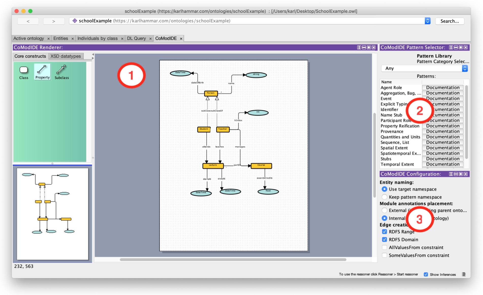
CoModIDE is developed as a plugin to the versatile and well-established Protégé ontology engineering environment. The plugin provides three Protégé views, and a tab that hosts these views (see Fig. 10). The schema editor view provides an a graphical overview of an ontology’s structure, including the classes in the ontology, their subclass relations, and the object and datatype properties in the ontology that relate these classes to one another and to datatypes. All of these entities can be manipulated graphically through dragging and dropping. The pattern library view provides a built-in copy of the MODL ontology design pattern library [53], sourced from various projects and from the ODP community wiki.1111 A user can drag and drop design patterns from the pattern library onto the canvas to instantiate those patterns as modules in their ontology. The configuration view lets the user configure the behavior of the other CoModIDE views and their components. For a detailed description, we refer the reader to the video walkthrough on the CoModIDE webpage.1212 We also invite the reader to download and install CoModIDE themselves, from that same site.
Fig. 10.
CoModIDE user interface featuring 1) the schema editor, 2) the pattern library, and 3) the configuration view.
When a pattern is dragged onto the canvas, the constructs in that pattern are copied into the ontology (optionally having their IRIs updated to correspond with the target ontology namespace), but they are also annotated using the OPLa vocabulary, to indicate 1) that they belong to a certain pattern-based module, and 2) what pattern that module implements. In this way module provenance is maintained, and modules can be manipulated (folded, unfolded, removed, annotated) as needed.
4.2.Evaluation method
We have evaluated CoModIDE through a four-step experimental setup, consisting of: a survey to collect subject background data (familiarity with ontology languages and tools), two modeling tasks, and a follow-up survey to collect information on the usability1313s of both Protégé and CoModIDE. The tasks were designed to emulate a MOMo process, where a conceptual design is developed and agreed upon by whiteboard prototyping, and a developer is then assigned to formalizing the resulting whiteboard schema diagram into an OWL ontology. Our experimental hypotheses were defined as follows:
H1. When using CoModIDE, a user takes less time to produce correct and reasonable output, than when using Protege.
H2. A user will find CoModIDE to have a higher SUS score than when using Protege alone.
During each of the modeling tasks, participants were asked to generate a reasonable and correct OWL file for the provided schema diagram. In order to prevent a learning effect, the two tasks utilized two different schema diagrams. To prevent bias arising from differences in task complexity, counterbalancing was employed (such that half the users performed the first task with standard Protégé and the second task with CoModIDE, and half did the opposite). The correctness of the developed OWL files, and the time taken to complete each task, were recorded (the latter was however, for practical reasons, limited to 20 minutes per task).
The following sections provide a brief overview of each of the steps. The source material for the entire experiment is available online.1414
4.2.1.Introductory tutorial
When recruiting our participants for this evaluation, we did not place any requirements on ontology modeling familiarity. However, to establish a shared baseline knowledge of foundational modeling concepts (such as one would assume participants would have in the MOMo scenario we try to emulate, see above), we provided a 10 minute tutorial on ontologies, classes, properties, domains, and ranges. The slides used for this tutorial may be found online with the rest of the experiment’s source materials.
4.2.2.a priori survey
The purpose of the a priori survey was to collect information relating to the participants base level familiarity with topics related to knowledge modeling, to be used as control variables in later analysis. We used a 5-point Likert scale for rating the accuracy of the following statements.
Finally, we asked the participants to describe their relationship to the test leader, (e.g. student, colleague, same research lab, not familiar).4.2.3.Modeling task A
Fig. 11.
Task A schema diagram.
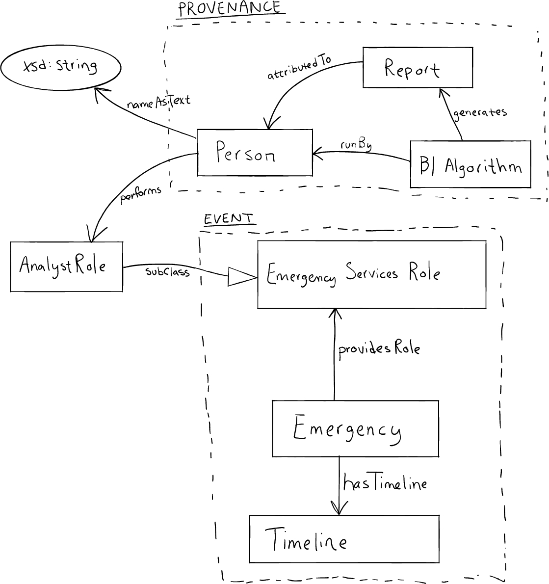
In Task A, participants were to develop an ontology to model how an analyst might generate reports about an ongoing emergency. The scenario identified two design patterns to use:
– Provenance: to track who made a report and how;
– Event: to capture the notion of an emergency.
Fig. 12.
Task B schema diagram.
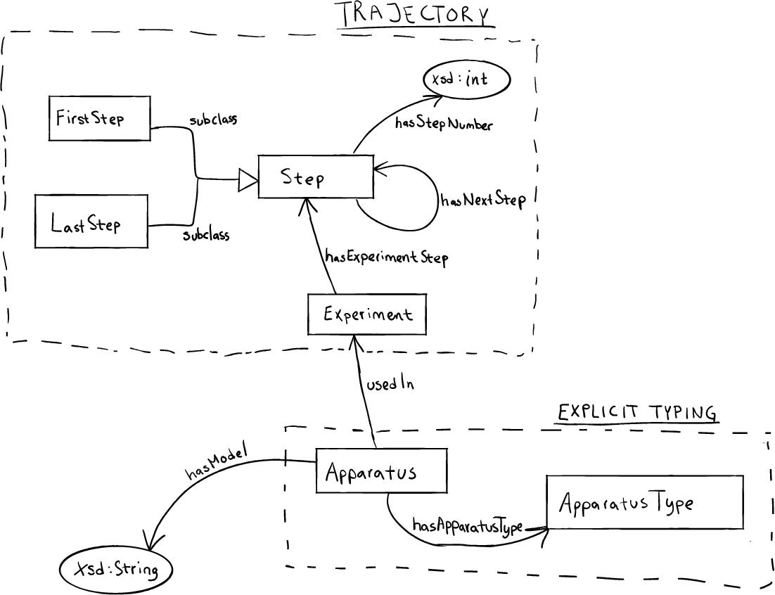
4.2.4.Modeling task B
In Task B, participants were to develop an ontology to capture the steps of an experiment. The scenario identified two design patterns to use:
– Trajectory: to track the order of the steps;
– Explicit Typing: to easily model different types of apparatus.
4.2.5.a posteriori survey
The a posteriori survey included the SUS evaluations for both Protégé and CoModIDE. The SUS is a very common “quick and dirty,” yet reliable tool for measuring the usability of a system. It consists of ten questions, the answers to which are used to compute a total usability score of 0–100. Additional information on the SUS and its included questions can be found online.1616
Additionally, we inquire about CoModIDE-specific features. These statements are also rated using a Likert scale. However, we do not use this data in our evaluation, except to inform our future work. Finally, we requested any free-text comments on CoModIDE’s features.
4.3.Results
4.3.1.Participant pool composition
Of the 21 subjects, 12 reported some degree of familiarity with the authors, while 9 reported no such connection. In terms of self-reported ontology engineering familiarity, the responses are as detailed in Table 2. It should be observed that responses vary widely, with a relative standard deviation (σ/mean) of 43–67 %.
4.3.2.Metric evaluation
We define our two metrics as follows:
– Time Taken: number of minutes, rounded to the nearest whole minute and capped at 20 minutes due to practical limitations, taken to complete a task;
– Correctness of Output is a discrete measure that corresponds to the structural accuracy of the output. That is, 2 points were awarded to structurally accurate OWL files; 1 point for a borderline case (e.g one or two incorrect linkages, or missing a domain statement but including the range); and 0 points for any other output.
Table 2
Mean, standard deviation, relative standard deviation, and median responses to a priori statements
| mean | σ | relative σ | median | |
| CV1 | 3.05 | 1.75 | 57 % | 3 |
| CV2 | 3.05 | 1.32 | 43 % | 3 |
| CV3 | 2.33 | 1.56 | 67 % | 1 |
| CV4 | 2.81 | 1.33 | 47 % | 3 |
| CV5 | 2.95 | 1.63 | 55 % | 3 |
Table 3
Summary of statistics comparing Protege and CoModIDE
| mean | σ | median | |
| Protégé | 17.44 | 3.67 | 20.0 |
| CoModIDE | 13.94 | 4.22 | 13.5 |
| (a) Mean, standard deviation, and median time taken to complete each modeling task. | |||
| mean | σ | median | |
| Protégé | 0.50 | 0.71 | 0.0 |
| CoModIDE | 1.33 | 0.77 | 1.5 |
| (b) Mean, standard deviation, and median correctness of output for each modeling task. | |||
| CV1 | CV2 | CV3 | CV4 | CV5 | |
| TT (P) | −0.61 | −0.18 | −0.38 | −0.58 | −0.62 |
| Cor. (P) | 0.50 | 0.20 | 0.35 | 0.51 | 0.35 |
| TT (C) | 0.02 | −0.34 | −0.28 | −0.06 | 0.01 |
| Cor. (C) | −0.30 | 0.00 | −0.12 | −0.33 | −0.30 |
| (c) Correlations control variables (CV) on the Time Taken (TT) and Correctness of Output (Cor.) for both tools Protégé (P) and CoModIDE (C). | |||||
| CV1 | CV2 | CV3 | CV4 | CV5 | |
| SUS (P) | 0.70 | 0.52 | 0.64 | 0.73 | 0.64 |
| SUS (C) | −0.34 | −0.05 | −0.08 | −0.29 | −0.39 |
| (d) Correlations with control variables (CV) on the SUS scores for both tools Protégé (P) and CoModIDE (C). | |||||
In addition, we examine the impact of our control variables (CV). This analysis is important, as it provides context for representation or bias in our data set. These are reported in Table 3(c). CV1–CV5 correspond exactly to those questions asked during the a priori Survey, as described in Section 4.2. For each CV, we calculated the bivariate correlation between the sample data and the self-reported data in the survey. We believe that this is a reasonable measure of impact on effect, as our limited sample size is not amenable to partitioning. That is, the partitions (as based on responses in the a priori survey) could have been tested pair-wise for statistical significance. Unfortunately, the partitions would have been too small to conduct proper statistical testing. However, we do caution that correlation effects are strongly impacted by sample size.
Table 4
Significance of results
| Time Taken | Correctness | SUS Evaluation |
Table 5
Mean, standard deviation, and median SUS score for each tool. The maximum score is 100
| mean | σ | median | |
| Protégé | 36.67 | 22.11 | 35.00 |
| CoModIDE | 73.33 | 16.80 | 76.25 |
We analyze the SUS scores in the same manner. Table 5 presents the mean, standard deviation, and median of the data set. The maximum score while using the scale is a 100. Table 3(d) presents our observed correlations with our control variables.
Finally, we compare each metric for one tool against the other. That is, we want to know if our results are statistically significant – that as the statistics suggest in Table 3, CoModIDE does indeed perform better for both metrics and the SUS evaluation. To do so, we calculate the probability p that the samples from each dataset come from different underlying distributions. A common tool, and the tool we employ here, is the Paired (two-tailed) T-Test – noting that it is reasonable to assume that the underlying data are normally distributed, as well a powerful tool for analyzing datasets of limited size. The threshold for indicating confidence that the difference is significant is generally taken to be
4.3.3.Free-text responses
Table 6
Free text comment fragments per category
| Code | Fragment # |
| Graph layout | 4 |
| Dragging & dropping | 6 |
| Feature requests | 5 |
| Bugs | 8 |
| Modeling problems | 5 |
| Value/preference statements | 9 |
18 of the 21 subjects opted to leave free-text comments. We applied fragment-based qualitative coding and analysis on these comments. I.e., we split the comments apart per the line breaks entered by the subjects, we read through the fragments and generated a simple category scheme, and we then re-read the fragments and applied these categories to the fragments (allowing at most one category per fragment) [9,49]. The subjects left between 1–6 fragments each for a total of 49 fragments for analysis, of which 37 were coded, as detailed in Table 6.
Of the 18 participants who left comments, 3 left comments containing no codable fragments; these either commented upon the subjects own performance in the experiment, which is covered in the aforementioned completion metrics, or were simple statements of fact (e.g., “In order to connect two classes I drew a connecting line”).
4.4.Discussion
4.4.1.Participant pool composition
The data indicates no correlation (bivariate correlation
4.4.2.Metric evaluation
Before we can determine if our results confirm H1 and H2, we must first examine the correlations between our results and the control variables gathered in the a priori survey. In this context, we find it reasonable to use these thresholds for a correlation
As shown in Table 3(c), the metric time taken when using Protégé is negatively correlated with each CV. The correctness metric is positively correlated with each CV. This is unsurprising and reasonable; it indicates that familiarity with the ontology modeling, related concepts, and Protégé improves (shortens) time taken to complete a modeling task and improves the correctness of the output. However, for the metrics pertaining to CoModIDE, there are only very weak and three weak correlations with the CVs. We may construe this to mean that performance when using CoModIDE, with respect to our metrics, is largely agnostic to our control variables.
To confirm H1, we look at the metrics separately. Time taken is reported better for CoModIDE in both mean and median. When comparing the underlying data, we achieve
This is particularly interesting; given the above analysis of CV correlations where we see no (or very weak) correlations between prior ontology modeling familiarity and CoModIDE modeling results, and the confirmation of H1, that CoModIDE users perform better than Protégé users, we have a strong indicator that we have achieved increased approachability.
When comparing the SUS score evaluations, we see that the usability of Protégé is strongly influenced by familiarity with ontology modeling and familiarity with Protégé itself. The magnitude of the correlation suggests that newcomers to Protege do not find it very usable. CoModIDE, on the other hand is, weakly, negatively correlated along the CV. This suggests that switching to a graphical modeling paradigm may take some adjusting.
However, we still see that the SUS scores for CoModIDE have a greater mean, tighter σ, and greater median, achieving a very strong statistical significance
As such, by confirming H1 and H2, we may say that CoModIDE improves the approachability of ontology engineering, especially for those not familiar with ontology modeling – with respect to our participant pool. However, we suspect that our results are generalizable, due to the strength of the statistical significance (Table 4) and participant pool composition (Section 4.3.1).
4.4.3.Free-text responses
The fragments summarized in Table 6 paints a quite coherent picture of the subjects’ perceived advantages and shortcomings of CoModIDE, as follows:
– Graph layout: The layout of the included MODL patterns, when dropped on the canvas, is too cramped and several classes or properties overlap, which reduces tooling usability.
– Dragging and dropping: Dragging classes was hit-and-miss; this often caused users to create new properties between classes, not move them.
– Feature requests: Pressing the “enter” key should accept and close the entity renaming window. Zooming is requested, and an auto-layout button.
– Bugs: Entity renaming is buggy when entities with similar names exist.
– Modeling problems: Self-links/loops cannot easily be modeled.
– Value/preference statements: Users really appreciate the graphical modeling paradigm offered, e.g., “Much easier to use the GUI to develop ontologies”, “Moreover, I find this system to be way more intuitive than Protégé”, “CoModIDE was intuitive to learn and use, despite never working with it before.”
4.5.CoModIDE 2.0
Since the evaluation, we have made plenty of progress on improving CoModIDE in significant ways. Aside from bug fixes and general quality of life improvements (i.e. versions 1.1.1 and 1.1.2) addressing many of the free-text responses in Section 4.4.3, we have implemented additional key aspects of the MOMo methodology. In particular, they are as follows.
– Modules are now directly supported. The grey boxes, as shown in Fig. 5, can now be created by highlighting a group of connected classes and datatypes and pressing ‘G’. These new nodes can be folded into a single cell in order to simplify large or complex diagrams. Outgoing edges are maintained from the collapsed node. Newly instantiated patterns (i.e. those dragged-and-dropped from the pattern library) appear pre-grouped into modules.
– OPLa Annotations are added whenever modules are created directly, and are properly retained when dragged-and-dropped from the pattern library. In particular, the isNativeTo and reusesPatternAsTemplate properties are currently supported. This generally subsumes the functionality of [52].
– The Systematic Axiomatization process from MOMo is now directly supported. By clicking on a named edge on the canvas, the user can now customize exactly what the edge represents in the “Edge Inspection Tool.” The list offers the human readable labels for the list of axioms generally used in the MOMo workflow, and described in Section 3.6.6.
In addition, we have added simple, manual alignment to external ontologies. More information on this upper alignment tool for CoModIDE can be found in [11].
In order to improve the extensibility of the platform, we have reworked the overarching conceptual framework for functionality in CoModIDE. Functionality is now categorized into so-called toolkits which communicate through a newly implemented message bus. This allows for a relatively straightforward integration process for external developers.
It is also important to recall that CoModIDE is not just a development platform, but a tool that enables research into ontology engineering. To that point, we have implemented an opt-in telemetry agent that collects and sends anonymized usage characteristics back to the developers. This records session lengths, clicks, and other such metrics that give us insight on how ontologies are authored in a graphical environment.
5.Additional infrastructure and resources
5.1.The modular ontology design library (MODL)
The Modular Ontology Design Library (MODL) is both an artifact and a framework for creating collections of ontology design patterns [53]. MODL is a method for establishing a well-curated and well-documented collection of ODPs that is structured using OPLa. This allows for a queryable interface when the MODL is very large, or if the MODL is integrated into other tooling infrastructure. For example, CoModIDE uses OPLa annotations to structure, define, and relate patterns in its internal MODL, as described in Section 4.1.
5.2.OPLa annotator
The OPLa Annotator [52] is a standalone plugin for Protégé. This plug-in allows for the guided creation of opla:isNativeTo annotations on ontological entities of an OWL file. While this particular functionality is subsumed in CoModIDE, it does not require the graphical canvas or the creation of modules, and can be a quicker option when the imposed graphical organization is not desired or required.
5.3.ROWLTab
ROWLTab [46] is another standalone plugin for Protégé. It is based on the premise that some ontology users, and frequently non-ontologists, find conceptualizing knowledge through rules to be more convenient. This plugin allows the user to enter SWRL rules which will then, when applicable, be converted into equivalent OWL axioms. An extension to this plug-in, detailed in [48], allows for existential rules.
5.4.SDOnt
SDOnt [50] is an early tool for generating schema diagrams from OWL files. Unlike other visual OWL generators, SDOnt does not give a strictly disambiguous diagram. Instead, it generates schema diagrams in the style that has been described in Section 3.2 based on the TBox of the input OWL file. This program only requires Java to run and can be run on any OWL ontology; although, as with any graph visualization, it tends to work best with smaller schemas.
5.5.Example modular ontologies
In this section, we provide a brief directory of existing modular ontologies, organized by modeling challenges. These can be used for inspiration to the prospective modeler, or, in the spirit of the MOMo methodology, the modeler may wish to reuse or adapt their modules to new or similar use cases.
Highly spatial data
It is frequently common to model data that has a strong spatial dimension. The challenges that accompany this are unfortunately myriad. In the GeoLink Modular Ontology [34] we utilize the Semantic Trajectory pattern to model discrete representations of continuous spatial movement. Ongoing work regarding the integration of multiple datasets (e.g., NOAA storm data, USGS earthquake data, and FEMA disaster declarations)1717 while using their spatial data as the dimension of integration can be found online.1818 The RealEstateCore Ontology [20,25] provides a set of patterns and modules for the integration of spatial footprints and structures in a real estate property with sensors and other devices present on the Internet of Things.
Elusive ground truth
Sometimes, it is necessary to model data where it is not known if it is true, or that it is necessary to knowingly ingest possibly contradictory knowledge. In this case, we suggest a records-based approach, with a strong emphasis on the first-class modeling of provenance. That is, knowledge or data is not modeled directly, but instead we model a container for the data, which is then strongly connected to its provenance. An example of this approach can be found in the Enslaved Ontology [54], where historical data may contradict or conflict with itself, based on the interpretations of different historians.
Rule-based knowledge
In some cases, it may be necessary to directly encode rules or conditional data, such as attempting to describe the action-response mechanisms when reacting to an event. The methods for doing so, and the modules therein associated, can be found in the Modular Ontology for Space Weather Research [57] and in the Domain Ontology for Task Instructions [13].
Shortcuts & views
Shortcuts and Views are used to manage complexity between rich and detailed ontological truthiness and convenience for data providers, publishers, and consumers. That is, it is frequently desirable to have high fidelity in the underlying knowledge model, which may result in a model that is confusing or unintuitive to the non-ontologist. As such, shortcuts can be used to simplify navigation or publishing according to the model. These shortcuts would also be formally described allowing for a navigation between levels of abstraction. A full examination of these constructs is out of scope, but examples of shortcuts and views, alongside their use, can be found in the Geolink Modular Ontology [34], the tutorial for modeling Chess Game Data [35], and in the Enslaved Ontology [54].
6.Conclusion
The re-use of ontologies for new purposes, or adapting them to new use-cases, is frequently very difficult. In our experiences, we have found this to be the case for several reasons: (i) differing representational granularity, (ii) lack of conceptual clarity of the ontology design, (iii) adhering to good modeling principles, and (iv) a lack of re-use emphasis and process support available in ontology engineering tooling. In order to address these concerns, we have developed the Modular Ontology Modeling (MOMo) workflow and supporting tooling infrastructure, CoModIDE (The Comprehensive Modular Ontology Integrated Development Environment – “commodity”).
In this paper, we have presented the MOMo workflow in detail, from introducing the schema diagram as the primary conceptual vehicle for communicating between ontology engineers and domain experts, to presenting several experiences in executing the workflow across many distinct domains with different use cases and data requirements.
We have also shown how the CoModIDE platform allows ontology engineers, irrespective of previous knowledge level, to develop ontologies more correctly and more quickly, than by using standard Protégé; that CoModIDE has a higher usability (SUS score) than standard Protégé; and that the CoModIDE issues that concern users primarily derive from shallow bugs as opposed to methodological or modeling issues. Taken together, this implies that the modular graphical ontology engineering paradigm is a viable way for supporting the MOMo workflow.
6.1.Future work
From here, there are still many avenues of investigation remaining, pertaining to both the MOMo workflow and CoModIDE.
Regarding the workflow, we will continue to execute the workflow in new domains and observe differences in experiences. Currently, we are examining how to better incorporate spatially-explicit modeling techniques. In addition, we wish to further explore how schema diagrams may represent distinctly different semantics, such as ShEx [4], SHACL [33], rather than OWL.
We also foresee the continued development of the platform. As mentioned in Section 4.5, we have improved its internal structure so that it may support bundled pieces of functionality. In particular, we will develop such toolkits for supporting holistic ontology engineering projects, going beyond just the modeling process. This will include the incorporation of ontology alignment systems so that CoModIDE may export automatic alignments alongside the designed deliverable, and the incorporation of recommendation software, perhaps based on input seed data. Further, we see a route for automatic documentation in the style of our own technical reports. Finally, we wish to examine collected telemetry data in order to analyse how users develop ontologies in a graphical modeling paradigm.
Notes
1 For more information on the Ontology Alignment Evaluation Initiative, see http://oaei.ontologymatching.org/.
2 These are ontological terms; a perdurant means “an entity that only exists partially at any given point in time” and endurant means “an entity that can be observed as a complete concept, regardless of the point time.”
3 Other divide and conquer approaches have also recently been proposed [41,59], and while they seem to be compatible with ours, exact relationships still need to be established.
6 Momo is the protagonist in the 1973 fantasy novel “Momo” by Michael Ende. The antagonists are Men in Grey that cause people to waste time.
7 The schema diagrams in this paper were produced with yEd, available from https://www.yworks.com/products/yed/.
8 This is similar to the schema:domainIncludes and schema:rangeIncludes from Schema.org. We note, however, that a structural tautology is slightly stricter, in that it directly pairs two concepts via the role, whereas Schema.org’s is a many-to-many approach.
9 We find that the size of partial solutions users typically develop fit on a medium-sized whiteboard; but whether this is a naturally manageable size for humans to operate with, or whether it is the result of constraints of or conditioning to the available tooling, i.e., the size of the whiteboards often mounted in conference rooms, we cannot say.
10 Our experience indicates that while our target users are generally enthusiastic about the idea of reusing design patterns, they are quickly turned off of the idea when they are faced with patterns that lack documentation or that exhibit link rot.
13 As according to the System Usability Scale (SUS) and described further in Section 4.2.2.
15 This is asked as Manchester Syntax is the default syntax in Protégé. The underlying assumption is that the manual addition of axioms with the expression editor in Protégé would be faster given familiarity with Manchester Syntax.
17 Respectively, these are National Oceanic and Atmospheric Administration, United States Geological Survey, and Federal Emergency Management Agency.
18 See https://knowwheregraph.org/.
Acknowledgements
Cogan Shimizu and Pascal Hitzler acknowledge partial support from the financial assistance award 70NANB19H094 from U.S. Department of Commerce, National Institute of Standards and Technology and the National Science Foundation under Grant No. 2033521 and the Andrew W. Mellon Foundation. The authors acknowledge the helpful input from Adila Krisnadhi and MD Kamruzzaman Sarker; and development support from Sulogna Chowdhury, Abhilekha Dalal, Riley Mueller, and Lu Zhou.
References
[1] | R. Agarwal and A.P. Sinha, Object-oriented modeling with UML: A study of developers’ perceptions, Commun. ACM 46: (9) ((2003) ), 248–256. doi:10.1145/903893.903944. |
[2] | A. Algergawy, S. Babalou, F. Klan and B. König-Ries, Ontology modularization with OAPT, J. Data Semant. 9: (2) ((2020) ), 53–83. doi:10.1007/s13740-020-00114-7. |
[3] | A. Algergawy, D. Faria, A. Ferrara, I. Fundulaki, I. Harrow, S. Hertling, E. Jiménez-Ruiz, N. Karam, A. Khiat, P. Lambrix, H. Li, S. Montanelli, H. Paulheim, C. Pesquita, T. Saveta, P. Shvaiko, A. Splendiani, É. Thiéblin, C. Trojahn, J. Vatascinová, O. Zamazal and L. Zhou, Results of the ontology alignment evaluation initiative 2019, in: Proceedings of the 14th International Workshop on Ontology Matching Co-Located with the 18th International Semantic Web Conference (ISWC 2019), Auckland, New Zealand, October 26, 2019, P. Shvaiko, J. Euzenat, E. Jiménez-Ruiz, O. Hassanzadeh and C. Trojahn, eds, CEUR Workshop Proceedings, Vol. 2536: , CEUR-WS.org, (2019) , pp. 46–85. |
[4] | T. Baker and E. Prud’hommeaux (eds), Shape Expressions (ShEx) 2.1 Primer, Final Community Group Report 09 October 2019, 2019, http://shex.io/shex-primer/index.html. |
[5] | E. Blomqvist, A. Gangemi and V. Presutti, Experiments on pattern-based ontology design, in: Proceedings of the 5th International Conference on Knowledge Capture (K-CAP 2009), September 1–4, 2009, Redondo Beach, California, USA, Y. Gil and N.F. Noy, eds, ACM, (2009) , pp. 41–48. doi:10.1145/1597735.1597743. |
[6] | E. Blomqvist, K. Hammar and V. Presutti, Engineering ontologies with patterns – the eXtreme Design methodology, in: Ontology Engineering with Ontology Design Patterns – Foundations and Applications, P. Hitzler, A. Gangemi, K. Janowicz, A. Krisnadhi and V. Presutti, eds, Studies on the Semantic Web, Vol. 25: , IOS Press, (2016) , pp. 23–50. doi:10.3233/978-1-61499-676-7-23. |
[7] | E. Blomqvist, V. Presutti, E. Daga and A. Gangemi, Experimenting with eXtreme design, in: Knowledge Engineering and Management by the Masses – 17th International Conference, EKAW 2010, Lisbon, Portugal, October 11–15, 2010. Proceedings, P. Cimiano and H.S. Pinto, eds, Lecture Notes in Computer Science, Vol. 6317: , Springer, (2010) , pp. 120–134. doi:10.1007/978-3-642-16438-5_9. |
[8] | E. Blomqvist and K. Sandkuhl, Patterns in ontology engineering: Classification of ontology patterns, in: ICEIS 2005, Proceedings of the Seventh International Conference on Enterprise Information Systems, Miami, USA, May 25–28, 2005, C. Chen, J. Filipe, I. Seruca and J. Cordeiro, eds, (2005) , pp. 413–416. |
[9] | P. Burnard, A method of analysing interview transcripts in qualitative research, Nurse Education Today 11: (6) ((1991) ), 461–466, https://www.sciencedirect.com/science/article/pii/026069179190009Y. doi:10.1016/0260-6917(91)90009-Y. |
[10] | S.S. Cherfi, J. Akoka and I. Comyn-Wattiau, Conceptual modeling quality – from EER to UML schemas evaluation, in: Conceptual Modeling – ER 2002, 21st International Conference on Conceptual Modeling, Tampere, Finland, October 7–11, 2002, Proceedings, S. Spaccapietra, S.T. March and Y. Kambayashi, eds, Lecture Notes in Computer Science, Vol. 2503: , Springer, (2002) , pp. 414–428. doi:10.1007/3-540-45816-6_38. |
[11] | A. Dalal, C. Shimizu and P. Hitzler, Modular ontology modeling meets upper ontologies: The upper ontology alignment tool, in: Proceedings of the ISWC 2020 Demos and Industry Tracks: From Novel Ideas to Industrial Practice Co-Located with 19th International Semantic Web Conference (ISWC 2020), Globally Online, November 1–6, 2020 (UTC), K.L. Taylor, R.S. Gonçalves, F. Lécué and J. Yan, eds, CEUR Workshop Proceedings, Vol. 2721: , CEUR-WS.org, (2020) , pp. 119–124, http://ceur-ws.org/Vol-2721/paper528.pdf. |
[12] | A. Eberhart, C. Shimizu, S. Chowdhury, Md.K. Sarker and P. Hitzler, Expressibility of OWL axioms with patterns, in: The Semantic Web – 18th International Conference, ESWC 2021, Virtual Event, June 6–10, 2021, Proceedings, R. Verborgh, K. Hose, H. Paulheim, P. Champin, M. Maleshkova, Ó. Corcho, P. Ristoski and M. Alam, eds, Lecture Notes in Computer Science, Vol. 12731: , Springer, (2021) , pp. 230–245. doi:10.1007/978-3-030-77385-4_14. |
[13] | A. Eberhart, C. Shimizu, C. Stevens, P. Hitzler, C.W. Myers and B. Maruyama, A domain ontology for task instructions, in: Knowledge Graphs and Semantic Web – Second Iberoamerican Conference and First Indo-American Conference, KGSWC 2020, Mérida, Mexico, November 26–27, 2020, Proceedings, B. Villazón-Terrazas, F. Ortiz-Rodríguez, S.M. Tiwari and S.K. Shandilya, eds, Communications in Computer and Information Science, Vol. 1232: , Springer, (2020) , pp. 1–13. doi:10.1007/978-3-030-65384-2_1. |
[14] | M. Egaña, R. Stevens and E. Antezana, Transforming the axiomisation of ontologies: The ontology pre-processor language, in: Proceedings of the Fourth OWLED Workshop on OWL: Experiences and Directions, Washington, DC, USA, 1–2 April 2008, K. Clark and P.F. Patel-Schneider, eds, CEUR Workshop Proceedings, Vol. 496: , CEUR-WS.org, (2008) , http://ceur-ws.org/Vol-496/owled2008dc_paper_14.pdf. |
[15] | M. Fernández-López, A. Gómez-Pérez and N. Juristo, METHONTOLOGY: From ontological art towards ontological engineering, Technical report, SS–97–06, American Association for Artificial Intelligence, 1997. |
[16] | G.O. Consortium, Gene ontology consortium: The gene ontology (GO) database and informatics resource, Nucleic Acids Research 32: (database-issue) ((2004) ), 258–261. doi:10.1093/nar/gkh036. |
[17] | A. Gangemi, Ontology design patterns for semantic web content, in: The Semantic Web – ISWC 2005, 4th International Semantic Web Conference, ISWC 2005, Galway, Ireland, November 6–10, 2005, Proceedings, Y. Gil, E. Motta, V.R. Benjamins and M.A. Musen, eds, Lecture Notes in Computer Science, Vol. 3729: , Springer, (2005) , pp. 262–276. doi:10.1007/11574620_21. |
[18] | B.C. Grau, I. Horrocks, Y. Kazakov and U. Sattler, Extracting modules from ontologies: A logic-based approach, in: Modular Ontologies: Concepts, Theories and Techniques for Knowledge Modularization, H. Stuckenschmidt, C. Parent and S. Spaccapietra, eds, Lecture Notes in Computer Science, Vol. 5445: , Springer, (2009) , pp. 159–186. doi:10.1007/978-3-642-01907-4_8. |
[19] | I. Hadar and P. Soffer, Variations in conceptual modeling: Classification and ontological analysis, J. Assoc. Inf. Syst. 7: (8) ((2006) ), 20, http://aisel.aisnet.org/jais/vol7/iss8/20. doi:10.17705/1jais.00096. |
[20] | K. Hammar, Ontology design patterns in use – lessons learnt from an ontology engineering case, in: Proceedings of the 3rd Workshop on Ontology Patterns, Boston, USA, November 12, 2012, E. Blomqvist, A. Gangemi, K. Hammar and M.C. Suárez-Figueroa, eds, CEUR Workshop Proceedings, Vol. 929: , CEUR-WS.org, (2012) , http://ceur-ws.org/Vol-929/paper2.pdf. |
[21] | K. Hammar, Ontology design pattern property specialisation strategies, in: Knowledge Engineering and Knowledge Management – 19th International Conference, EKAW 2014, Linköping, Sweden, November 24–28, 2014. Proceedings, K. Janowicz, S. Schlobach, P. Lambrix and E. Hyvönen, eds, Lecture Notes in Computer Science, Vol. 8876: , Springer, (2014) , pp. 165–180. doi:10.1007/978-3-319-13704-9_13. |
[22] | K. Hammar, Ontology design patterns in WebProtégé, in: Proceedings of the ISWC 2015 Posters & Demonstrations Track Co-Located with the 14th International Semantic Web Conference (ISWC-2015), Bethlehem, PA, USA, October 11, 2015., S. Villata, J.Z. Pan and M. Dragoni, eds, CEUR Workshop Proceedings, Vol. 1486: , CEUR-WS.org, (2015) , http://ceur-ws.org/Vol-1486/paper_50.pdf. |
[23] | K. Hammar, Content ontology design patterns: Qualities, methods, and tools, PhD thesis, Linköping University, Sweden, 2017. doi:10.3384/diss.diva-139584. |
[24] | K. Hammar and V. Presutti, Template-based content ODP instantiation, in: Advances in Ontology Design and Patterns [Revised and Extended Versions of the Papers Presented at the 7th Edition of the Workshop on Ontology and Semantic Web Patterns, WOP@ISWC 2016, Kobe, Japan, 18th October 2016], K. Hammar, P. Hitzler, A. Krisnadhi, A. Lawrynowicz, A.G. Nuzzolese and M. Solanki, eds, Studies on the Semantic Web, Vol. 32: , IOS Press, pp. 1–13. doi:10.3233/978-1-61499-826-6-1. |
[25] | K. Hammar, E.O. Wallin, P. Karlberg and D. Hälleberg, The RealEstateCore ontology, in: The Semantic Web – ISWC 2019, Lecture Notes in Computer Science, Vol. 11779: , Springer, Cham, (2019) , pp. 130–145, https://doi.org/10.1007/978-3-030-30796-7_9. doi:10.1007/978-3-030-30796-7_9. |
[26] | Q. Hirt, C. Shimizu and P. Hitzler, Extensions to the ontology design pattern representation language, in: Proceedings of the 10th Workshop on Ontology Design and Patterns (WOP 2019) Co-Located with 18th International Semantic Web Conference (ISWC 2019), Auckland, New Zealand, October 27, 2019, K. Janowicz, A.A. Krisnadhi, M. Poveda-Villalón, K. Hammar and C. Shimizu, eds, CEUR Workshop Proceedings, Vol. 2459: , CEUR-WS.org, (2019) , pp. 76–75, http://ceur-ws.org/Vol-2459/short2.pdf. |
[27] | P. Hitzler, A review of the semantic web field, Commun. ACM 64: (2) ((2021) ), 76–83. doi:10.1145/3397512. |
[28] | P. Hitzler, A. Gangemi, K. Janowicz, A. Krisnadhi and V. Presutti (eds), Ontology Engineering with Ontology Design Patterns – Foundations and Applications, Studies on the Semantic Web, Vol. 25: , IOS Press, (2016) . ISBN 978-1-61499-676-7. |
[29] | P. Hitzler, A. Gangemi, K. Janowicz, A.A. Krisnadhi and V. Presutti, Towards a simple but useful ontology design pattern representation language, in: Proceedings of the 8th Workshop on Ontology Design and Patterns (WOP 2017) Co-Located with the 16th International Semantic Web Conference (ISWC 2017), Vienna, Austria, October 21, 2017., E. Blomqvist, Ó. Corcho, M. Horridge, D. Carral and R. Hoekstra, eds, CEUR Workshop Proceedings, Vol. 2043: , CEUR-WS.org, (2017) , http://ceur-ws.org/Vol-2043/paper-09.pdf. |
[30] | P. Hitzler and A. Krisnadhi, On the roles of logical axiomatizations for ontologies, in: Ontology Engineering with Ontology Design Patterns – Foundations and Applications, P. Hitzler, A. Gangemi, K. Janowicz, A. Krisnadhi and V. Presutti, eds, Studies on the Semantic Web, Vol. 25: , IOS Press, (2016) , pp. 73–80. doi:10.3233/978-1-61499-676-7-73. |
[31] | Y. Hu, K. Janowicz, D. Carral, S. Scheider, W. Kuhn, G. Berg-Cross, P. Hitzler, M. Dean and D. Kolas, A geo-ontology design pattern for semantic trajectories, in: Spatial Information Theory – 11th International Conference, COSIT 2013, Scarborough, UK, September 2–6, 2013. Proceedings, T. Tenbrink, J.G. Stell, A. Galton and Z. Wood, eds, Lecture Notes in Computer Science, Vol. 8116: , Springer, (2013) , pp. 438–456. doi:10.1007/978-3-319-01790-7_24. |
[32] | N. Karima, K. Hammar and P. Hitzler, How to document ontology design patterns, in: Advances in Ontology Design and Patterns [Revised and Extended Versions of the Papers Presented at the 7th Edition of the Workshop on Ontology and Semantic Web Patterns, WOP@ISWC 2016, Kobe, Japan, 18th October 2016], K. Hammar, P. Hitzler, A. Krisnadhi, A. Lawrynowicz, A.G. Nuzzolese and M. Solanki, eds, Studies on the Semantic Web, Vol. 32: , IOS Press, (2016) , pp. 15–27. doi:10.3233/978-1-61499-826-6-15. |
[33] | H. Knublauch and D. Kontokostas (eds), Shapes Constraint Language (SHACL), W3C Recommendation 20 July 2017, 2017, https://www.w3.org/TR/shacl/. |
[34] | A. Krisnadhi, Ontology design patterns for data integration: The GeoLink experience, in: Ontology Engineering with Ontology Design Patterns – Foundations and Applications, P. Hitzler, A. Gangemi, K. Janowicz, A. Krisnadhi and V. Presutti, eds, Studies on the Semantic Web, Vol. 25: , IOS Press, (2016) , pp. 267–278. doi:10.3233/978-1-61499-676-7-267. |
[35] | A. Krisnadhi and P. Hitzler, Modeling with ontology design patterns: Chess games as a worked example, in: Ontology Engineering with Ontology Design Patterns – Foundations and Applications, P. Hitzler, A. Gangemi, K. Janowicz, A. Krisnadhi and V. Presutti, eds, Studies on the Semantic Web, Vol. 25: , IOS Press, (2016) , pp. 3–21. doi:10.3233/978-1-61499-676-7-3. |
[36] | J. Krogstie, Evaluating UML using a generic quality framework, in: UML and the Unified Process, IGI Global, (2003) , pp. 1–22. doi:10.4018/978-1-93177-744-5.ch001. |
[37] | Linked Open Vocabularies (LOV), Accessed: 2021-05-06, https://lov.linkeddata.es/dataset/lov/. |
[38] | S. Lohmann, V. Link, E. Marbach and S. Negru, WebVOWL: Web-based visualization of ontologies, in: Knowledge Engineering and Knowledge Management – EKAW 2014 Satellite Events, VISUAL, EKM1, and ARCOE-Logic, Linköping, Sweden, November 24–28, 2014. Revised Selected Papers, P. Lambrix, E. Hyvönen, E. Blomqvist, V. Presutti, G. Qi, U. Sattler, Y. Ding and C. Ghidini, eds, Lecture Notes in Computer Science, Vol. 8982: , Springer, (2014) , pp. 154–158. doi:10.1007/978-3-319-17966-7_21. |
[39] | S. Lohmann, S. Negru, F. Haag and T. Ertl, Visualizing ontologies with VOWL, Semantic Web 7: (4) ((2016) ), 399–419. doi:10.3233/SW-150200. |
[40] | W.C. Mann and S.A. Thompson, Rhetorical Structure Theory: A Theory of Text Organization, Information Sciences Institute, University of Southern California, Los Angeles, (1987) . |
[41] | D. Osumi-Sutherland, M. Courtot, J.P. Balhoff and C.J. Mungall, Dead simple OWL design patterns, J. Biomed. Semant. 8: (1) ((2017) ), 18:1–18:7. doi:10.1186/s13326-017-0126-0. |
[42] | S. Peroni, A simplified agile methodology for ontology development, in: OWL: – Experiences and Directions – Reasoner Evaluation – 13th International Workshop, OWLED 2016, and 5th International Workshop, ORE 2016, Bologna, Italy, November 20, 2016, Revised Selected Papers, M. Dragoni, M. Poveda-Villalón and E. Jiménez-Ruiz, eds, Lecture Notes in Computer Science, Vol. 10161: , Springer, (2016) , pp. 55–69. doi:10.1007/978-3-319-54627-8_5. |
[43] | H.S. Pinto, S. Staab, C. Tempich and Y. Sure, Distributed engineering of ontologies (DILIGENT), in: Semantic Web and Peer-to-Peer – Decentralized Management and Exchange of Knowledge and Information, S. Staab and H. Stuckenschmidt, eds, Springer, (2006) , pp. 303–322. doi:10.1007/3-540-28347-1_16. |
[44] | S. Sahoo, D. McGuinness and T. Lebo, PROV-O: The PROV ontology, W3C Recommendation, W3C, 2013, http://www.w3.org/TR/2013/REC-prov-o-20130430/. |
[45] | Md.K. Sarker, D. Carral, A.A. Krisnadhi and P. Hitzler, Modeling OWL with rules: The ROWL protege plugin, in: Proceedings of the ISWC 2016 Posters & Demonstrations Track Co-Located with 15th International Semantic Web Conference (ISWC 2016), Kobe, Japan, October 19, 2016, T. Kawamura and H. Paulheim, eds, CEUR Workshop Proceedings, Vol. 1690: , CEUR-WS.org, (2016) , http://ceur-ws.org/Vol-1690/paper92.pdf. |
[46] | Md.K. Sarker, A. Krisnadhi, D. Carral and P. Hitzler, Rule-based OWL modeling with ROWLTab Protégé plugin, in: The Semantic Web – 14th International Conference, ESWC 2017, Portorož, Slovenia, May 28 – June 1, 2017, Proceedings, Part I, E. Blomqvist, D. Maynard, A. Gangemi, R. Hoekstra, P. Hitzler and O. Hartig, eds, Lecture Notes in Computer Science, Vol. 10249: , (2017) , pp. 419–433. doi:10.1007/978-3-319-58068-5_26. |
[47] | Md.K. Sarker, A.A. Krisnadhi and P. Hitzler, OWLAx: A protege plugin to support ontology axiomatization through diagramming, in: Proceedings of the ISWC 2016 Posters & Demonstrations Track Co-Located with 15th International Semantic Web Conference (ISWC 2016), Kobe, Japan, October 19, 2016, T. Kawamura and H. Paulheim, eds, CEUR Workshop Proceedings, Vol. 1690: , CEUR-WS.org, (2016) , http://ceur-ws.org/Vol-1690/paper83.pdf. |
[48] | S.J. Satpathy, Rules with right hand existential or disjunction with ROWLTab, Master’s thesis, Wright State University, 2019. |
[49] | C.B. Seaman, Qualitative methods, in: Guide to Advanced Empirical Software Engineering, F. Shull, J. Singer and D.I.K. Sjøberg, eds, Springer London, London, (2008) , pp. 35–62. ISBN 978-1-84800-044-5. doi:10.1007/978-1-84800-044-5_2. |
[50] | C. Shimizu, A. Eberhart, N. Karima, Q. Hirt, A. Krisnadhi and P. Hitzler, A method for automatically generating schema diagrams for OWL ontologies, in: Knowledge Graphs and Semantic Web – First Iberoamerican Conference, KGSWC 2019, Villa Clara, Cuba, June 23–30, 2019, Proceedings, B. Villazón-Terrazas and Y. Hidalgo-Delgado, eds, Communications in Computer and Information Science, Vol. 1029: , Springer, (2019) , pp. 149–161. doi:10.1007/978-3-030-21395-4_11. |
[51] | C. Shimizu, K. Hammar and P. Hitzler, Modular graphical ontology engineering evaluated, in: The Semantic Web – 17th International Conference, ESWC 2020, Heraklion, Crete, Greece, May 31–June 4, 2020, Proceedings, A. Harth, S. Kirrane, A.N. Ngomo, H. Paulheim, A. Rula, A.L. Gentile, P. Haase and M. Cochez, eds, Lecture Notes in Computer Science, Vol. 12123: , Springer, (2020) , pp. 20–35. doi:10.1007/978-3-030-49461-2_2. |
[52] | C. Shimizu, Q. Hirt and P. Hitzler, A Protégé plug-in for annotating OWL ontologies with OPLa, in: The Semantic Web: ESWC 2018 Satellite Events – ESWC 2018 Satellite Events, Heraklion, Crete, Greece, June 3–7, 2018, Revised Selected Papers, A. Gangemi, A.L. Gentile, A.G. Nuzzolese, S. Rudolph, M. Maleshkova, H. Paulheim, J.Z. Pan and M. Alam, eds, Lecture Notes in Computer Science, Vol. 11155: , Springer, (2018) , pp. 23–27. doi:10.1007/978-3-319-98192-5_5. |
[53] | C. Shimizu, Q. Hirt and P. Hitzler, MODL: A modular ontology design library, in: WOP@ISWC, CEUR Workshop Proceedings, Vol. 2459: , CEUR-WS.org, (2019) , pp. 47–58. |
[54] | C. Shimizu, P. Hitzler, Q. Hirt, D. Rehberger, S.G. Estrecha, C. Foley, A.M. Sheill, W. Hawthorne, J. Mixter, E. Watrall, R. Carty and D. Tarr, The Enslaved Ontology: Peoples of the historic slave trade, Journal of Web Semantics 63: ((2020) ), 100567. doi:10.1016/j.websem.2020.100567. |
[55] | C. Shimizu, P. Hitzler, Q. Hirt, A. Shiell, S. Gonzalez, C. Foley, D. Rehberger, E. Watrall, W. Hawthorne, D. Tarr, R. Carty and J. Mixter, The enslaved ontology 1.0: People of the historic slave trade, Technical report, Michigan State University, East Lansing, Michigan, 2019, available from https://daselab.cs.ksu.edu/projects/ontology-modeling-slave-trade. |
[56] | C. Shimizu, P. Hitzler and A. Krisnadhi, Modular ontology modeling: A tutorial, in: Applications and Practices in Ontology Design, Extraction, and Reasoning, G. Cota, M. Daquino and G.L. Pozzato, eds, Studies on the Semantic Web, Vol. 49: , IOS Press, (2020) , pp. 3–20. doi:10.3233/SSW200032. |
[57] | C. Shimizu, R. McGranaghan, A. Eberhart and A.C. Kellerman, Towards a modular ontology for space weather research, in: Advances in Pattern-Based Ontology Engineering, E. Blomqvist, T. Hahmann, K. Hammar, P. Hitzler, R. Hoekstra, R. Mutharaju, M. Poveda-Villalón, C. Shimizu, M.G. Skjæveland, M. Solanki, V. Svátek and L. Zhou, eds, Studies on the Semantic Web, Vol. 51: , IOS Press, (2021) . doi:10.3233/SSW210021. |
[58] | P. Shoval and I. Frumermann, OO and EER conceptual schemas: A comparison of user comprehension, Journal of Database Management (JDM) 5: (4) ((1994) ), 28–38. doi:10.4018/jdm.1994100103. |
[59] | M.G. Skjæveland, D.P. Lupp, L.H. Karlsen and H. Forssell, Practical ontology pattern instantiation, discovery, and maintenance with reasonable ontology templates, in: The Semantic Web – ISWC 2018 – 17th International Semantic Web Conference, Monterey, CA, USA, October 8–12, 2018, Proceedings, Part I, D. Vrandecic, K. Bontcheva, M.C. Suárez-Figueroa, V. Presutti, I. Celino, M. Sabou, L. Kaffee and E. Simperl, eds, Lecture Notes in Computer Science, Vol. 11136: , Springer, (2018) , pp. 477–494. doi:10.1007/978-3-030-00671-6_28. |
[60] | H. Stuckenschmidt, C. Parent and S. Spaccapietra (eds), Modular Ontologies: Concepts, Theories and Techniques for Knowledge Modularization, Lecture Notes in Computer Science, Vol. 5445: , Springer, (2009) . ISBN 978-3-642-01906-7. doi:10.1007/978-3-642-01907-4. |
[61] | Y. Sure, S. Staab and R. Studer, On-to-knowledge methodology (OTKM), in: Handbook on Ontologies, S. Staab and R. Studer, eds, International Handbooks on Information Systems, Springer Berlin Heidelberg, (2004) , pp. 117–132. doi:10.1007/978-3-540-24750-0_6. |
[62] | V. Wiens, S. Lohmann and S. Auer, WebVOWL editor: Device-independent visual ontology modeling, in: Proceedings of the ISWC 2018 Posters & Demonstrations, Industry and Blue Sky Ideas Tracks Co-Located with 17th International Semantic Web Conference (ISWC 2018), Monterey, USA, October 8th – to – 12th, 2018, M. van Erp, M. Atre, V. López, K. Srinivas and C. Fortuna, eds, CEUR Workshop Proceedings, Vol. 2180: , CEUR-WS.org, (2018) , http://ceur-ws.org/Vol-2180/paper-75.pdf. |
[63] | O. Zamazal and V. Svátek, The ten-year OntoFarm and its fertilization within the onto-sphere, J. Web Semant. 43: ((2017) ), 46–53. doi:10.1016/j.websem.2017.01.001. |


