
New type sand compaction pile method for densification of liquefiable ground underneath existing structure
Abstract
The 2011 Great East Japan Earthquake caused severe damage to infrastructures due to liquefaction, in which many embankments failed with large settlement and slope failure. Sand Compaction Pile method is one of the typical ground improvement methods to densify the ground by installing compacted sand piles into ground. This method has been often applied to mitigate the liquefaction. However, current SCP method of constructing sand piles in vertical direction is not able to densify ground underneath an existing structure. For applying the method to an existing structure, a new type of SCP method was recently developed where in compacted sand columns can be constructed in any direction. This paper briefly introduces the new type of SCP method and the effectiveness of local densification by numerical analysis. In this manuscript, a series of numerical analyses were conducted to evaluate the effect of shape and location of SCP improved zone on the dynamic response of embankment. This paper describes the numerical analyses as well as the development, machinery and procedure of the technique, and emphasizes the uniqueness and effectiveness of the technique for preventing liquefaction for new and existing structures.
1Introduction
In Japan, soft alluvial ground is frequently encountered on land and marine constructions. Sandy soil has relatively preferable properties for compressibility, but liquefaction might happen during earthquake in case of loose and saturated condition. In fact, many infrastructures were heavily damaged in the 1995 Hyogoken-Nambu earthquake and the 2011 Tohoku earthquake and tsunami. Many kinds of soil stabilization techniques were developed and available in Japan for countermeasure for liquefaction. Among them, Sand Compaction Pile (SCP) method has been developed in 1956 whose principal concept is to increase the ground density by feeding a certain amount of granular material (usually sand) in the ground [1]. Effectiveness of the method as liquefaction countermeasure was firstly confirmed at the 1978 Miyagi-ken Oki earthquake in Japan and ever since the method has been often adopted for many construction projects. In the construction procedure, a casing pipe is penetrated into a ground vertically and during the withdrawal stage sand is fed into a ground through a casing pipe and is compacted by vibration, dynamic impact or static excitation to construct a compacted sand pile in the ground.
As infrastructures being developed in Japan, new technology is required to reinforce not only new but also existing structures against anticipated huge earthquakes in future, where ground underneath the structure should be compacted in the condition of limited working space. Upon this, a quite unique sand compaction pile method, SAVE-SP method, was developed in 2008 which enables to install sand piles vertically or at an angle in the ground [2]. In the method, granular sand is fluidized by mixing with special agent and water, and is injected into ground through a small diameter pipe. The injected soil in the ground becomes granular state by a slow-acting retarding plasticizer to create compacted sands. As the machine for this method is small, it enables to construct at any direction underneath structure, which is expected to prevent liquefaction more effectively. On the other hand, it encourages establishing a new design procedure for precise evaluation of the improvement effect.
In this manuscript, a series of numerical analyses was conducted to evaluate the effect of shape and location of SCP improved zone on the dynamic response of embankment. This paper describes the numerical analyses as well as the development, machinery and procedure of the technique, which emphasizes the uniqueness and effectiveness of the technique for preventing liquefaction for new and existing structures.
2Outline of new type sand compaction pile method
2.1Outline of the method
Sand Compaction Pile (SCP) method was first developed in 1956 and has been frequently applied to sandy ground and clay ground, where sand injected into a ground was compacted by a vibrator installed on the top of casing pipe (vibratory SCP method). In order to minimize adverse influence to surrounding caused by the vibrator, non-vibratory type SCP method was developed in 1995 (Silent, Advanced Vibration-Erasing Composer, SAVE method), where sand injected into a ground was statically compacted by the forced lifting/driving device instead of the vibrator. In recent years, it is required to prevent liquefaction of ground underneath existing structure such as building, river levee and airport runway. A sand injection type SCP method (SAVE-SP method) was developed for the requirement as shown in Fig. 1. In the method, granular sand is fluidized by mixing with special agent and water, and is injected into ground through a small diameter pipe. The injected soil in the ground becomes granular state by a slow-acting retarding plasticizer to create compacted sands, as shown in Fig. 2. On the basis of the principle that this method depends on the operation to inject sand into ground and to compact surrounding ground, the fluidized sand is required to have antipodal properties of the fluidity by keeping water-retainability to avoid pipe clogging and the modestly drainable characteristics to dissipate in order to obtain instantaneous high density of sand when pumped into the ground. Also, slow-acting retarding plasticizer is added to the fluidized sand to vanish the effect of fluidizing reagent after released into the ground. Figure 3 compares the size of the threemethods.
The characteristics of this method can be summarized as follow:
1) The small-sized execution machine as shown in Fig. 3 enables to operate it at limited working space and/or within a limited working time.
2) The method is carried out through a small bore hole of about 10 cm in diameter, which enables to minimize to influence to infrastructures in operation
3) Sand pile is manufactured by static manner instead of dynamic, which provides negligible vibration and noise influence to surrounding.
4) The method is remarkably economic compared with conventional liquefaction countermeasures available to work at small working space and/or for improvement underneath existing structures.
5) It is ecological and easily assimilates to the ground as natural sand is used.
2.2Machine and execution
The machine system for this method is, as shown in Fig. 1, consists of a small-sized driving machine, a conveying pump, a mixing plant for producing the fluidized sand, and a backhoe for supplying sand in the hopper. The machine system occupies a small area of about 3 m by 6 m. In the mixing plant, the fluidized sand is produced by mixing water, fluidizing reagent and retarding plasticizer with sand, and then transferred to the execution machine by a piston/cylinder type pump to the maximum distance of about 100 m.
Figure 4 shows the construction procedure, which is similar manner. The steps from (1) to (4) can perform the same quality of compaction as the conventional SCP.
(1) After positioning machine, a casing rod is drilled and is installed to design depth.
(2) Fluidized sand is discharged from the bottom end of the rod and compressed to manufacture a sand pile of 70 cm in diameter
(3) The rod is lifted up the rod about 20 cm for next discharged
(4) Repeat step (2) and (3) to design upper level to manufacture compacted sand pile. The fluidizing sand discharged into the ground becomes to granular state gradually by the retarding plasticizer agent.
2.3Case history of improvement for existing structures [3]
In this section, one of case histories of the method is briefly introduced where it was applied to improve the seismic behavior of a river dyke close to private houses. Figure 6 shows the ground condition at the site and the improvement cross section. This method was selected based on its low noise and vibration during execution for minimizing adverse influence to river back side and its small space occupancy to river front side.
Several sand and clay layers are stratified at the site as shown in Fig. 6, whose total thickness is about 15 m and the SPT-N values varied 1 to 20 along the depth. The target improvement layers are two alluvial sand layers and a clay layer named AUs, ALs and ALc respectively. In the execution, a small sand fill was constructed temporarily on the house side slope of the river dyke as a platform for the machine. The sand piles were constructed at 3 to 8 rows to form square arrangement of 1.2 to 1.9 m spacing. The piles’ length was 2 to 14 m while the drilling length from the dyke crest was 9 to 21 m. The two driving machines were used as shown in Fig. 7, where the fluidized sand was manufactured and supplied from one mixing plant located about 100 m far from the site to avoid adverse noise problem to the houses.
Figure 8 shows the distribution of SPT-N values along the depth before and after the improvement. The figure clearly confirms that the SPT-N values of the layers were increased to about 20 which could achieve the design requirement. The figure also shows another SPT-N value for comparison that was measured at the river side of the dyke improved by non-vibratory type of SCP method, SAVE method. The figure shows that almost the same increase in SPT-N value could be achieved by the two types of SCP methods even if the machine of the SAVE-SP method is quite small.
3Numerical analyses
As mentioned above, the new type of SCP method enables us to improve ground underneath existing structure with any arbitrary shape of the compacted portion. This method encourages finding the most effective shape and location of improvement for seismic stability of superstructure. A series of dynamic finite element analyses was carried out to investigate the effect of the shape and location of improved portion on the ground response and deformation mechanism of embankment and ground.
3.1Ground condition and analysis model
Two dimensional finite element analyses were con-ducted under the plain strain condition [4]. An embankment on a loose sandy ground is exemplified in the analyses as shown in Fig. 9 according to the documents and sources which analyzed the damages of embankments in the 2011 Great East Japan Earthquake [5, 6]. The sand layer with a thickness of 7 m at the surface is underlaid by the clay layer with a thickness of 3 m, and the deepest layer is 10 m thick gravel layer. The water level is set at a depth of 0.5 m from ground surface. The configuration of embankment is determined from the design standards [7], where the soil parameters of soil layers are listed in Table 1.
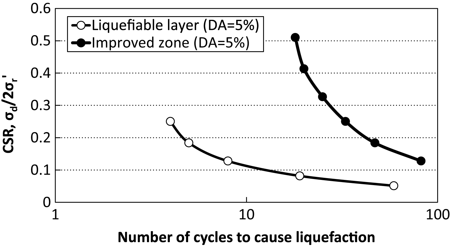
For the liquefiable layer (sand layer) and improved zone, the extended sub-loading surface model proposed by Hashiguchi and Chen [8] was adopted to simulate the accumulation of pore water pressure due to the cyclic shear shearing. Their SPT-N value and fine content (Fc), the density of soil particle (ρs) and the permeability (k) were assumed based on those at a certain damaged site and other parameters were assumed by the empirical correlations and the cyclic undrained triaxial tests. Figure 2 shows the liquefaction strength curve of the soils used for the liquefiable layer and improvement zone. The improvement ratio of improvement zone is set to 20 % throughout the analyses.
The clay layer and gravel layer modeled by Drucker-Prager model were assumed as a non-liquefiable layer in the analysis, where the accumulation of pore water pressure is not considered. The SPT-N value, the plasticity index (Ip), the density of soil particle (ρs), permeability (k), of clay layer were assumed. For the gravel layer, the SPT-N value and density of soil particle (ρs), permeability (k), were assumed. Other parameters for these two layers were determined using the empirical correlations.
The embankment in a dry condition is simulated by the extended sub-loading surface model proposed by Hashiguchi and Chen model [8] to simulate its dynamic behavior. In the analyses, two types of embankment were simulated to investigate the effect of its density on the dynamic behavior: (a) loosely compacted condition and (b) well compacted condition. The soil parameters of the conditions were the same as the liquefiable layer and the improvement zone respectively.
The soils saturated with water are sheared under the undrained condition, i.e., no seepage flow is considered in this analysis. System damping was represented by stiffness proportional damping, and the damping ratio used was 1% in the first mode of free vibration system. Number of node of analysis model is 5,673 and that of the element is 5,460. The boundary conditions of the ground are summarized in Table 2. The side boundaries of analytical domain are distant from the embankment and set to be periodic boundary condition.
3.2Input earthquake motion
The dynamic response and deformation behavior of ground is affected by many factors such as the frequency characteristic, the phase or amplitude of earthquake motion. The earthquake motion used in the analysis was shown in Fig. 11, which was measured at the ground surface in the 2008 Iwate-Miyagi Earthquake [9]. The input earthquake motion is applied to the base of model, parallel to the ground surface.
3.3Analysis cases
Total of 10 cases were analysis changing the ground improvement type and the compaction degree of embankment as shown in Table 3 and Fig. 12: (a) block improvement, (b) side improvement, (c) valleyed improvement and (d) V-shaped improvement, and non-improvement. The block improvement simulates a case where the liquefiable foundation ground right beneath the embankment is improved before the embankment construction (Fig. 12(a)). The side improvement is presently the most common improvement case by ordinal SCP method for seismic ground improvement of an existing embankment, where the liquefiable layer beside the embankment is improved instead of beneath the embankment (Fig. 12(b)). The valleyed improvement and V-shaped improvement cases are expected applications for the SAVE-SP method, where the sand piles are driven from the side of embankment at an angle. The valleyed improvement derives the case where the working area is limited (Fig. 12(c)). The V-shaped improvement derives the case of the same size working area as the side improvement case, where the liquefiable layer beneath the embankment is improved in parallelogram (Fig. 12(d)).
3.4Results and discussions
As the detail discussions of the analyses were presented in the literature [10], the analyses in the well compacted cases are briefly discussed in this manuscript.
3.4.1Excess pore water pressure
The excess pore water pressure time histories in the ground under the embankment (at –2.25 m) are shown in Fig. 13. In the cases of no-improvement and side improvement, the excess pore water pressure increases at first but decreases during shaking, which is sensitively due to the lateral stretching of the foundation ground. This in turn indicates that densification right outside of the embankment is not stiff enough to restrict the lateral displacement in the ground. In the cases of the valleyed improvement and V-shaped improvement, the excess pore water pressure increases and is kept high value during shaking, since they functions to restrict the stretch of the unimproved area under the embankment. This reveals that the effect of the improved zone having high stiffness on the restriction of the deformation of the unimproved ground is variable depend on the shape and location of the improvedzone.
The excess pore water pressure ratio (Δu/σv0’) distribution after shaking are shown in Fig. 14 for various improvement pattern as well as no-improvement case. The excess pore water pressure ratio reaches 1.0 in the liquefiable layer at the free field, which means that this area is totally liquefied. In the cases of no-improvement and side improvement, it is found that the excess pore water ratio remains relatively small value beneath the embankment. This is due to the lateral stretching mentioned above, which was also confirmed in the centrifuge tests and the numerical analyses [11, 12]. Figure 14(b) clearly shows that the ratio remains quite small value in the improved zone even subjected to shaking, which indicates that liquefaction does not take place there. In the cases of the valleyed improvement and the V-shaped improvement (Figs. 14(d) and (e)), it is found that the ratio increases to 1.0 in the unimproved area beneath the embankment, which indicates liquefaction takes place there. They reveals that it may be difficult to prevent the liquefaction in the unimproved area under the embankment locally even in the valleyed improvement and the V-shaped improvement in the in these improvement cases.
3.4.2Settlement of embankment
The settlement of the embankment may be caused by several factors as illustrated in Fig. 15, which may be classified into (a) lateral stretching of embankment, (b) volumetric compression of embankment, (c) lateral flow of foundation ground, and (d) volumetric compression of foundation ground [13]. Figure 16 shows these components of the embankment settlement. Since the analysis is conducted under undrained condition, the volumetric compression of the ground should be zero. Figure shows that the settlement component due to the volumetric compression of embankment can be negligible as the embankment is assumed to be well compacted in the analysis. It is found that the settlement of embankment due to the lateral flow of ground is dominant in the all cases except the block improvement. In the case of the block improvement, the settlement due to it is quite small value, about 1/4 of that in no improvement. In the cases of the side, valleyed and V-shaped improvements, the settlement due to it is not so small but becomes to about 3/4 of that in no improvement, which reveals the effectiveness of the improvement beneath the embankment. For the settlement component due to the lateral flow of embankment, any shape of improvement can function to reduce it, which is about 1/2 in irrespective of the shape of improvement. The total settlement of embankment is the smallest, about 30% of the no improvement in the block improvement beneath embankment. Three other improvements also show their effect on reducing the settlement to about 74% of the no improvement.
3.4.3Horizontal and vertical strain distributions
The effect of geometry of improved zone on the dynamic behavior of ground is discussed by comparing the two improvement cases: the side improvement and the valleyed improvement. Figure 17 shows the horizontal and vertical strain distributions along the center line of embankment for various stages, where the compression strain is represented in positive value. According to Fig. 11, the 5, 15, 25 and 50 sec. in the figure correspond to the initial stage of main shaking, at the immediate end of large shaking, at the end of main shaking and at the end of calculation, respectively.
In the case of the side improvement (Fig. 17(a)), relatively large horizontal tensile strain occurs in the deep portion of ground, about –7 to –5 m from the ground surface at the initial and soon after the main shaking. These behaviors correspond to the horizontal displacement in the deep portion of ground as shown in Fig. 8. It is found that the horizontal tensile strain also takes place in the embankment. The horizontal tensile strain tends to predominate in the deep portion soon after the large shaking 15 sec. According to the behavior mentioned above, it can be said that not only the whole portion of the embankment but also the deep portion of the ground under the embankment laterally stretch during shaking.
In the case of the valleyed improvement, the horizontal tensile strain in the shallow portion of the ground tends to predominate, while that in the embankment tends to decrease as it get closer to the crest. This tendency was also seen in the V-shaped improvement case. Therefore, it can be said that the area around the embankment crest tends to be compressed, while the lower part of the embankment laterally stretches during shaking. This suggests that the volleyed or V-shaped improvement can minimize the serious earthquake-induced cracking at the crest, although the marked advantage cannot be seen in reducing the total settlement.
4Concluding remarks
In this manuscript, the outline of the new type of SCP method and the numerical analyses were presented to emphasize the effectiveness of improvement underneath existing embankment on liquefaction prevention and stability increase of embankment.
The new type SCP method was developed where granular sand is fluidized to inject into the ground and then re-granulated to manufacture compacted sand piles. This method has many advantages such as high applicability to improvement underneath existing structure, low noise and vibration to minimize adverse influence to surrounding. The case history also shows high improvement performance which is almost same as the ordinary SCP method. The numerical analyses were carried out to discuss the effect of improvement underneath the embankment on the liquefaction prevention and stability of embankment. The analyses reveal that the improvement underneath the embankment, valleyed and V-shaped improvements, prevents the lateral stretching of the ground beneath embankment which can provide increase of embankment stability and reduction of embankment settlement.
Last but not the least, a lot of research efforts and new ground improvement techniques are required to reinforce not only new but also existing structures against anticipated huge earthquakes in future.
References
[1] | Kitazume M . The Sand Compaction Pile Method, Taylor & Francis, (2005) . |
[2] | Imai Y , Ohbayashi J , Fukushima S , Itoh T . Improvement effectiveness and application of sand-injection type static compaction method. Proc of the 54th Geotechnical Engineering Symposium. (2009) ;579–84. (in Japanese). |
[3] | Kubo Y , Uno M , Nakade Y , Fukada H , Takeuchi H . Application examples of sand- injection type static compaction method for earthquake-resistant strengthening work in Shonai River. Proc of the 22nd Technical Session on Investigation, Design and Construction of Japanese Geotechnical Engineering in Chubu Region, (2013) . (in Japanese). |
[4] | Takahashi A . Soil-pile interaction in liquefaction- induced lateral spreading of soils. D. Eng. dissertation, Tokyo Institute of Technology. (2002) . |
[5] | Kanto Regional Development Bureau, Ministry of Land, Infrastructure, and Transport. Analysis on failure mechanism and factor of failure on levees Material-4. 3rd meeting on investigation of restoration methods of levees in Kanto District. 2011. (in Japanese). |
[6] | Tohoku Regional Development Bureau, Ministry of Land, Infrastructure, and Transport. Report on restoration methods of levees in Kitakami River. 2011. (in Japanese). |
[7] | Japan River Association. Government ordinance for structural standard for river administration facilities. 2008. (in Japanese). |
[8] | Hashiguchi K , Chen Z-P . Elastoplastic constitutive equation of soils with the subloading surface and the rotational hardening. International Journal for Numerical and Analytical Methods in Geomechanics. (1998) ;22: (3):197–227. |
[9] | National Research Institute for Earth Science and Disaster Prevention. K-NET, KiK-net. [cited 2013. Aug 17]. Available from: http://www.kyoshin.bosai.go.jp/cgi-bin/kyoshin/getdata.cgi?0+IWTH24+KiK-net. |
[10] | Takahashi A , Sato N . Influence of ground improvement geometry on seismic response of liquefiable ground. Proc Taiwan–Japan Symposium on the Advancement of Urban Earthquake Hazard Mitigation Technology, Jhongli, Taiwan, (2014) ;17–20. |
[11] | Koga Y , Matsumoto O . Shaking table tests of embankment resting on liquefiable sandy ground. Soils and Foundations. Japanese Society of Soil Mechanics and Foundation Engineering, (1990) ;30: (4):162–74. |
[12] | Tobita T , Iai S , Ueda K . Dynamic behavior of embankments resting on liquefiable sandy deposits. Proc of the 3rd International Conference on Urban Earthquake Engineering. Tokyo, Japan. (2006) ;113–20. |
[13] | Okamura M , Matsuo O . Effects of remedial measures for mitigating embankment settlement due to foundation liquefaction, International Journal on Physical Modelling in Geotechnics. (2002) ;2: (2):1–12. |
Figures and Tables
Fig.1
SAVE-SP machine and mixing plant.
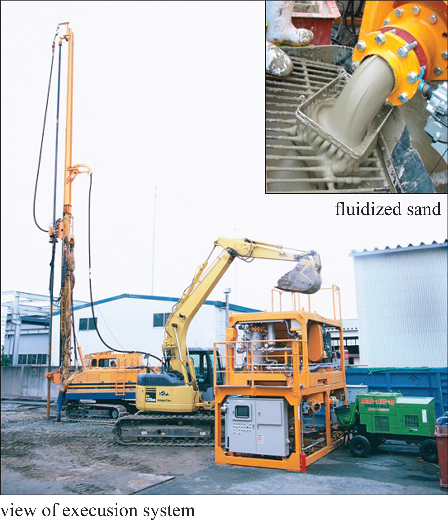
Fig.2
Schematic view of mechanism of the method.
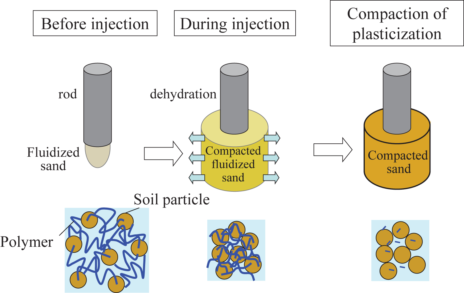
Fig.3
Comparison in execution machine scale.
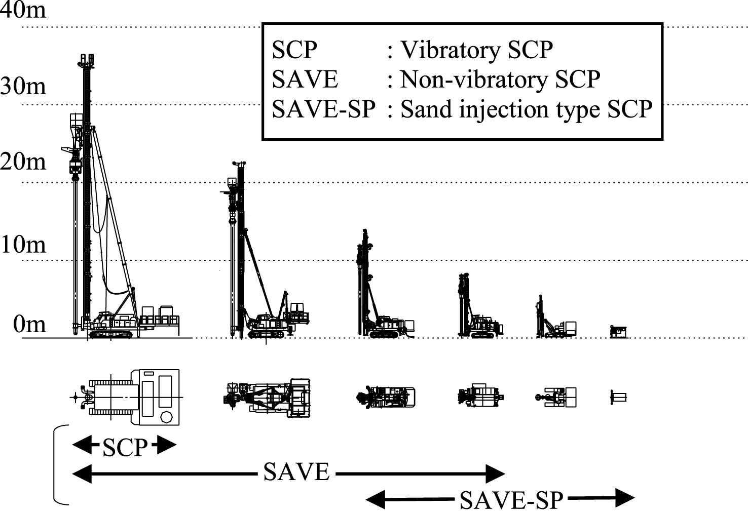
Fig.4
Process for implementation.
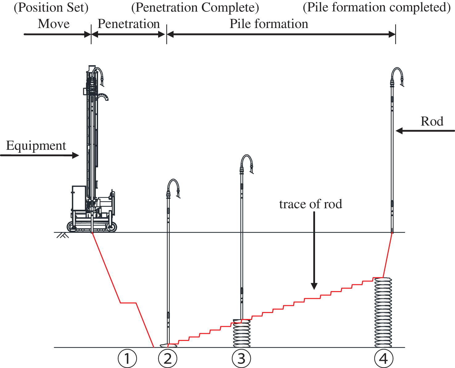
Fig.5
Mechanism for compaction.
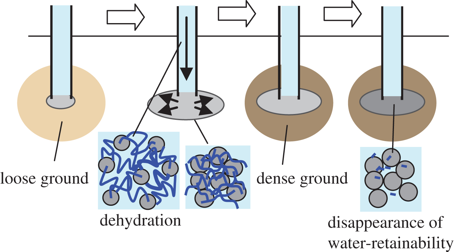
Fig.6
Cross section and soil condition of the site and arrangement of sand piles.
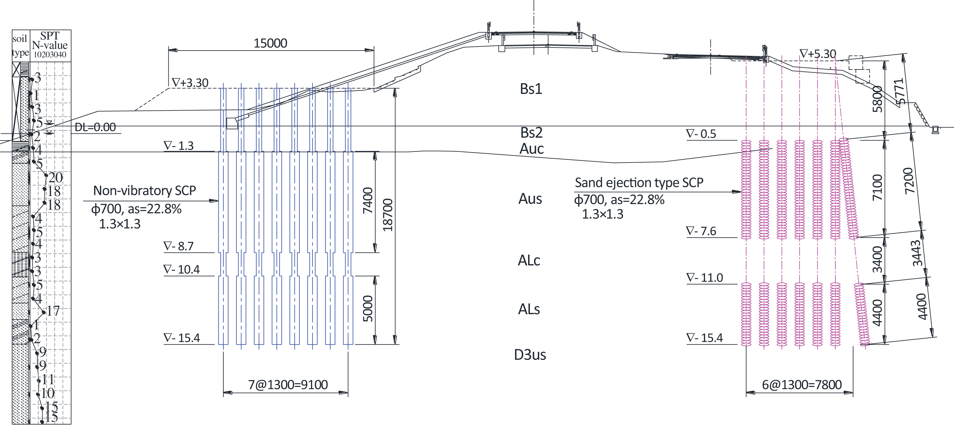
Fig.7
Machines working at state.
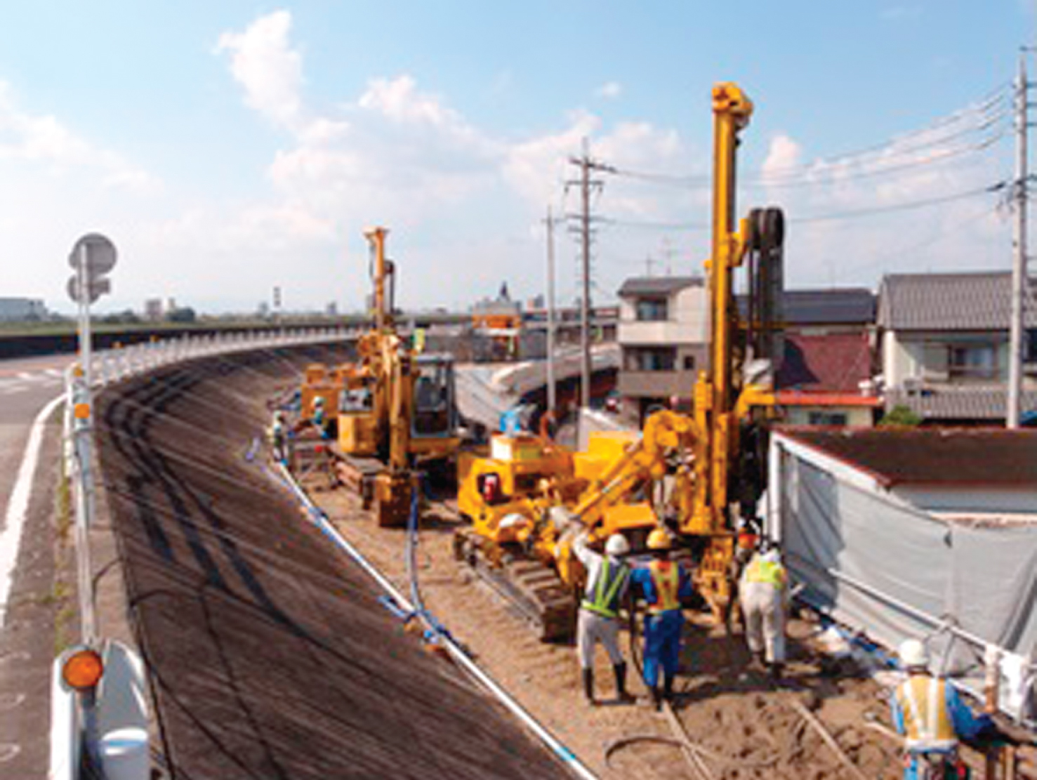
Fig.8
SPT-N value distributions before and after improvement.
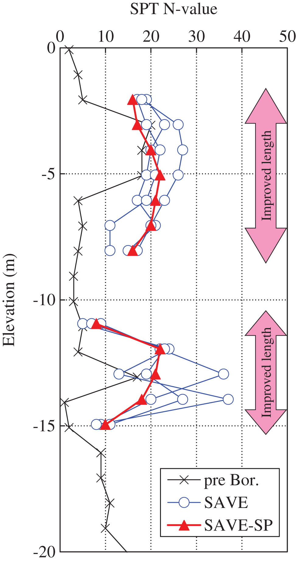
Fig.9
Model ground analyzed.
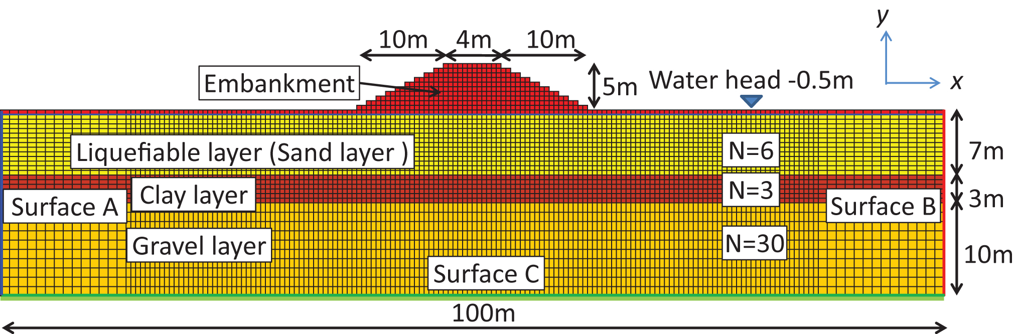
Fig.10
Relation between cyclic stress ratio and number of cycles to cause liquefaction.
![Input earthquake motion (2003 Iwate-Miyagi Earthquake [8]).](https://content.iospress.com:443/media/jgs/2016/3-1/jgs-3-1-jgs150032/jgs-3-jgs150032-g011.jpg)
Fig.12
Analysis cases (improvement condition). (a) Block improvement (IM1L, IM1W), (b) Side improvement (IM2L, IM2W), (c) Valleyed improvement (IM3L, IM3W), (d) V-shaped improvement (IM4L, IM4W).
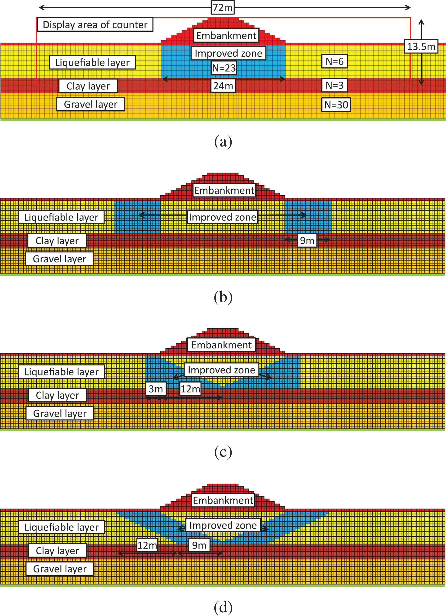
Fig.13
Excess pore water pressure time history in the foundation ground under the embankment (– 2.25 m).
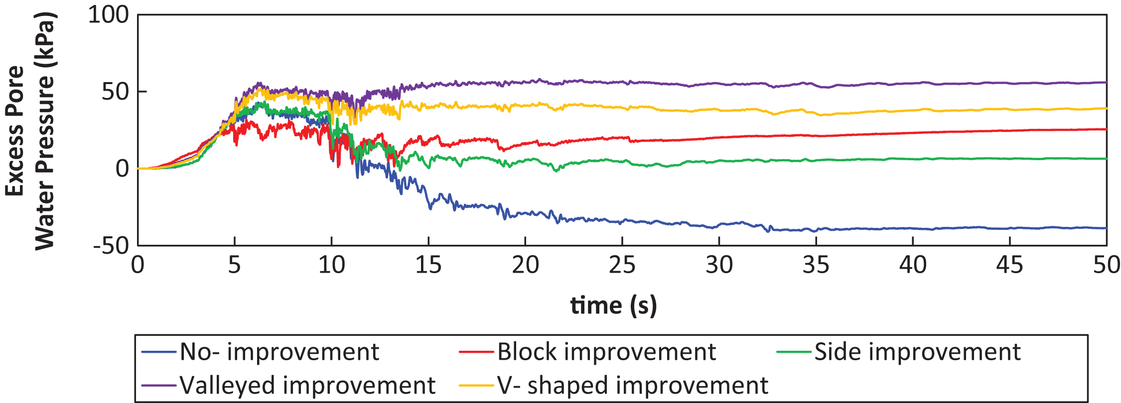
Fig.14
Excess pore water pressure ratio distribution after shaking (Well compacted cases).
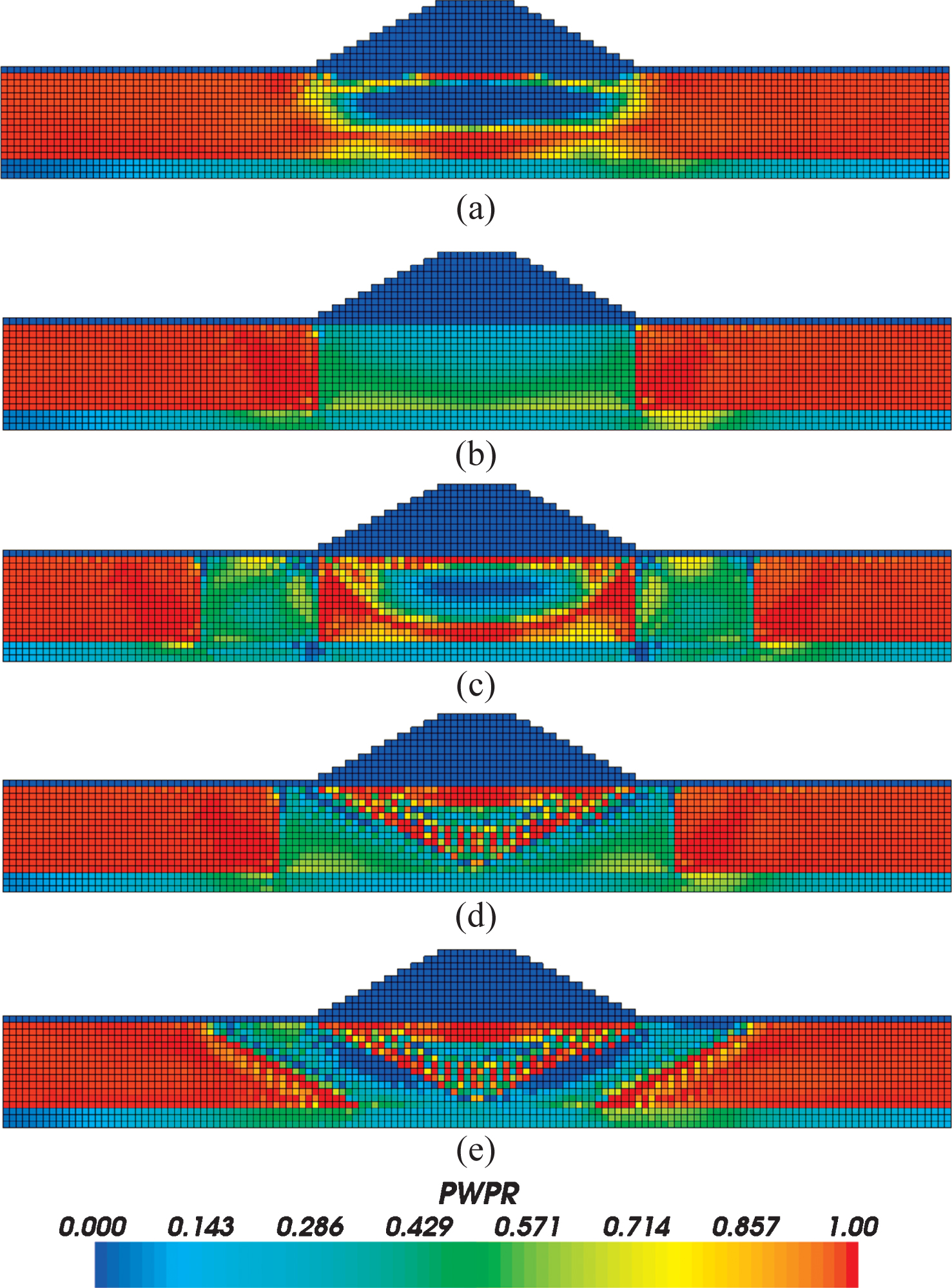
Fig.15
Primary factors of settlement.
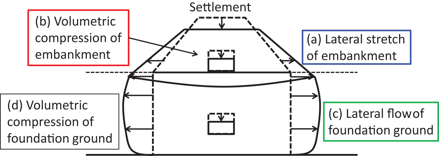
Fig.16
Crest settlement (Well compacted cases).
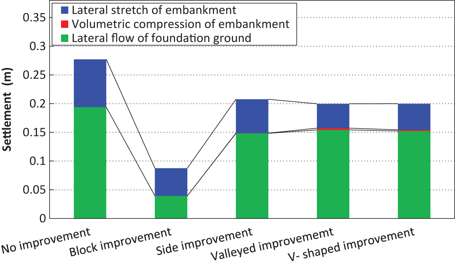
Fig.17
Horizontal and vertical strain distributions at center of embankment. (a) Side improvement (IW2W), (b) Valleyed improvement (IW3W).
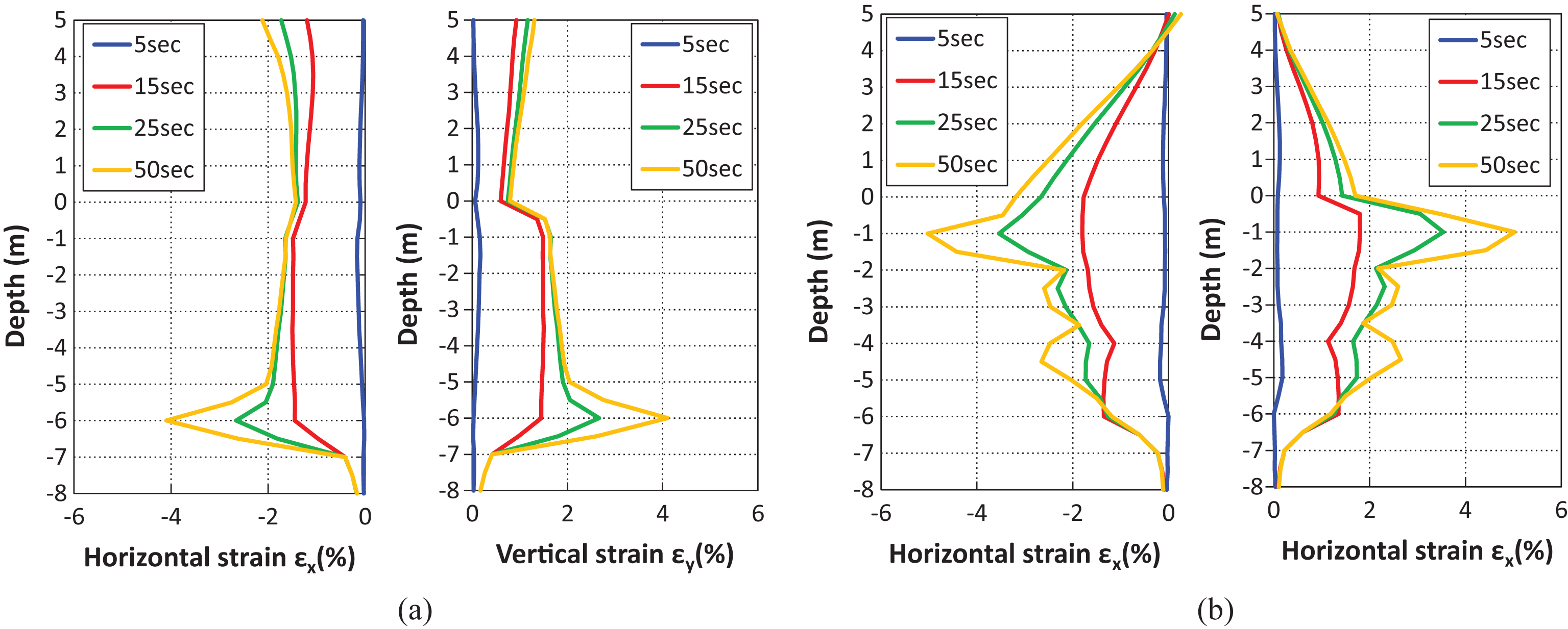
Table 1
Soil parameters
| Liquefiable layer and Improved zone (Hashiguchi and Chen model) | ||
| Parameter | Liquefiable layer | Improved zone |
| κ | 0.0013 | 0.00036 |
| λ | 0.0339 | 0.0198 |
| e0 | 0.944 | 0.729 |
| ν | 0.33 | 0.28 |
| ρs (Mg/m3) | 2.7 | 2.7 |
| φ (°) | 30.4 | 37.7 |
| φ d (°) | 25 | 25 |
| μ | 1.5 | 0.4 |
| φ b (°) | 20 | 20 |
| br | 100 | 20 |
| u1 | 4 | 2.5 |
| m1 | 2 | 2.5 |
| c | 20 | 3 |
| k (m/s) | 5.0×10⁻⁵ | 5.0×10⁻⁵ |
| OCR | 1.2 | 4.7 |
| sij0/σij0 | 0.1 | 0.01 |
| K0 | 0.5 | 0.4 |
| Clay layer and Gravel layer (Drucker- Prager model) | ||
| Parameter | Clay layer | Gravel layer |
| E98 (N/m2) | 1.38 × 10⁸ | 3.57 × 10⁹ |
| e0 | 1.14 | 0.45 |
| φ | 0.33 | 0.33 |
| ρs (Mg/m3) | 2.65 | 2.70 |
| c (N/m2) | 31300 | 0 |
| φ (°) | 0 | 40 |
| ψ (°) | 0 | 10 |
| k (m/s) | 1.0 × 10⁻⁸ | 5.0 × 10⁻⁵ |
Table 2
Boundary conditions
| Name | Initial stress analysis | Dynamic analysis | ||
| X | Y | X | Y | |
| A | Fix | Free | Periodic | Free |
| B | Periodic | Free | Periodic | Free |
| C | Fix | Fix | Fix | Fix |
| Other nodes | Free | Free | Free | Free |
Table 3
Analysis cases
| No | Name | Improvement type | Embankment |
| 1 | IM0L | No improvement | Loosely compacted |
| 2 | IM1L | Block improvement | |
| 3 | IM2L | Side improvement | |
| 4 | IM3L | Valleyed improvement | |
| 5 | IM4L | V-shaped improvement | |
| 6 | IM0W | No improvement | Well compacted |
| 7 | IM1W | Block improvement | |
| 8 | IM2W | Side improvement | |
| 9 | IM3W | Valleyed improvement | |
| 10 | IM4W | V-shaped improvement |


