
Numerical investigation of the effect of vacuum insulation panels on the thermal bridges of a lightweight drywall envelope
Abstract
This paper addresses the thermal bridges issues of a two storey lightweight steel framed envelope in which the VIPs are placed in an inner “protected” layer of the external walls. This configuration provides “protection” for the VIPs, allows flexibility in installation of facade elements and at the same time permits interventions and modifications (e.g. drilling, installation of appliances) on the internal side of the wall. The envelope is extensively analysed in terms of all the different types of thermal bridges utilizing commercial computational tools and standardized methodologies, and their effect on the overall thermal performance is evaluated. A total improvement of 33% on the heat transfer coefficient of the building is calculated. Results indicate the junctions between the external and internal walls, the external walls and the ceiling, the internal walls and the roof and the internal walls and the floor, respectively, as the most crucial thermal bridges. Different design modifications and solutions are assumed in order to further reduce the impact of the most crucial thermal bridges. The implementation of the modifications resulted in a further reduction of the overall thermal losses by 27.5%, leading to an overall thermal loss reduction by 60.5% as compared to the reference building.
1Introduction
Nowadays, the building sector has a lion’s share in energy consumption (U.S. EIA, 2015). One of the most efficient ways to reduce the energy demands of a building is the installation of insulation at the building envelope. An innovative insulation solution, which reaches thermal conductivity values less than 5 mW/(m K) (the value refers to the centre of panel), is the Vacuum Insulation Panel (VIP), whose insulation capability is approximately seven times better than that of conventional insulation materials, such as mineral wool or EPS. It consists of an evacuated, open pore core material (typically mainly out of pyrogenic silica) surrounded by thin barrier laminates, consisting of a multilayer of metalized films, and a sealing film all laminated together, used to maintain the high level of vacuum. VIPs are already used in appliances such as refrigerators and deep-freezers (Hammond & Evans, 2014), however recently many researchers investigate their share and use in the building sector (Alam, Singh, & Limbachiya, 2011, Simmler & Brunner, 2005, Kalnaes & Jelle, 2014, Mandilaras, Atsonios, Zannis, & Founti, 2014). During the last decade, awareness has grown for the need of advanced building shells which combine high thermal performance with short construction times and maximum constructive simplification. Hence, lightweight constructions coupled with VIPs form an attractive solution due to the advantages they offer, such as the low construction time, structural seismic resistance, the reduction and recyclability of wastes, the decrease of loads and costs on bearing structures and the high insulation capability (De Angelis & Serra, 2014). The concept of standardized lightweight steel framed residential buildings, aiming to build more buildings in a short period with fewer resources, is currently being investigated in the framework of the FP7 ELISSA project (www.elissaproject.eu). Walls are made of drywall materials (i.e. gypsum and cement boards) anchored on a lightweight steel frame structure.
One of the main challenges of the steel framed lightweight constructions is related to the effect of the thermal bridges. Crucial areas of the building envelope, such as near the steel components of the construction, where the otherwise uniform thermal resistance is greatly affected by materials with a different thermal conductivity and/or a change in thickness of the elements, establish thermal bridges (Zalewski, Lassue, Rousse, & Boukhalfa, 2010). Multidimensional heat flows are generated at these regions, which may induce a high risk of condensation and mould growth due to the low internal superficial temperature, with a negative impact on the structure and the indoor environmental quality (Evola, Margani, & Marletta, 2011).
Many researchers have studied the impact of the thermal bridges on the total energy demands of a building. Theodosiou and Papadopoulos (2008) showed that the heating need can be 30% higher than the one calculated without taking into account the thermal bridge effects at a typical three-storey building in Greece. De Angelis and Serra (2014) presented that without considering the metal studs the thermal transmittance of a lightweight wall is underestimated by ca. 67– 74%. Capozzoli et al. (Capozzoli, Gorrino & Corrado, 2013) showed that the thickness of the insulation layer is one of the most important variables affecting the deviation of the linear thermal transmittance. Evola et al. (Evola et al., 2011) showed that by reducing the effect of thermal bridges using external insulation, the heating requirements are restricted to ca. 17– 25%, while the annual energy demand is reduced by ca. 8% in the Mediterranean climate. The innovative insulation of modern buildings with VIPs induces thermal bridge effects, which are related to three levels of thermal bridges: VIP level, component and facade levels (Quenard, 2015, Sprengard & Holm, 2014), that should be calculated (Alam et al., 2011).
The scope of this study is to evaluate the impact of an additional layer of VIPs at the inner side of the external wall on the thermal bridges introduced in a lightweight building envelope, as well as to propose potential design modifications for further reduction of the thermal bridges. The assessment of the thermal bridges is based on the standard EN ISO 12011 (EN ISO 10211, 2007), coupling detailed numerical simulations of the thermal bridges with the standardized methodology. The influence of the thermal bridges due to the metal studs, two and three dimension junctions on the overall thermal transmittance of the envelope is examined both without and with VIPs at the inner side of the external wall of the building envelope. Finally, the impact of the potential design modifications, for the regions with high thermal bridging effects, on the overall thermal performance of the building is also analysed.
2Description of the building
In order to assess the impact of the thermal bridges on the overall thermal performance of the construction, a two storey building is analysed. It is a lightweight steel framed construction based on a cavity wall system. The metal skeleton is founded on a cement base and the dry-wall system envelope is anchored on the steel skeleton. The overall dimensions of the building are 4.5 m × 2.5 m × 5.3 m.
The elements of the External Walls (EW) are anchored on three different types of metal studs, i.e. C, CW (smaller C type) and I type. An additional VIP layer is placed in the internal side of the external walls. The schematic diagram of the external wall configuration is depicted in Figure 1 for the cases without (Fig. 1a) and with VIPs (Fig. 1b). The layers of the roof (RF) and the floor (FL) elements are anchored on I-type studs, 200 mm wide. Figures 1c and 1d show the schematic diagram of the roof configuration (Fig. 1c) and floor (Fig. 1d). It should be mentioned that the suspended part of the roof (i.e. resilient channel) is considered to be filled with conventional mineral wool. In the floor, a 180 mm thick mineral wool layer is placed inside the cavity, while a 150 mm thick foundation concrete slab and 500 mm of soil were assumed for the analysis of the current work. The configuration of the ceiling (CL) (i.e. between the 1st and the 2nd floor) is similar to that of the floor excluding the concrete layer and the soil, with the suspended part utilized in the roof. The Internal Wall (IW) consists of two gypsum boards on the two sides of the wall and mineral wool (120 mm) with air cavity (30 mm) at the intermediate, resulting in a total thickness of 207 mm.
3Methodology
The methodology followed in order to assess the impact of the thermal bridges on the total thermal performance of the building is based on EN ISO 10211 (EN ISO 10211, 2007). Numerical simulations are performed for the calculation of the thermal transmittance for each configuration.
3.1Assessment of building thermal performance
The main concept of the standardized methodology is the partitioning of the building into 1D, 2D and 3D geometrical models, as shown in Figure 2. The 1D geometrical model stands for the centre of the wall assembly, including the steel studs, while the 2D and 3D geometrical models stand for the 2D and 3D junctions of the walls, respectively (e.g. external wall and roof, external wall and inside wall and ceiling etc.), including the steel studs of the junction.
After partitioning the building, the transmission heat transfer coefficient, HD, is calculated by Equation 1:
(1),
3.2Calculation of linear and point thermal transmittance
The linear thermal transmittance, Ψ, concerns the two dimension geometries and is calculated according to Equation 2:
(2),
The point thermal transmittance, χ, of a part of the building envelope is calculated according to Equation 3:
(3),
The thermal transmittance of the 1D component, U-value, at each component, is calculated according to EN ISO 6946 (EN ISO 6946, 2007) taking into account the physical properties (i.e. thermal conductivity and thickness) of the materials composing the assemblies.
It should be noted that in the above equations (i.e. Equations 1, 2 and 3), the linear and point thermal bridges refer to the steel skeleton and the geometry of the facade, i.e. level 3 according to Quenard (Quenard, 2014), and not to the thermal bridges due to the laminate barrier of the VIP, i.e. level 1 as reported in Brunner, Stahl & Ghazi Wakili (2012a).
3.3Numerical simulation
In the current work, the two and three-dimensional thermal coupling coefficients, L2D and L3D, were numerically calculated for all the junctions of the building envelope, covering all the thermal bridges introduced due to the presence of the steel frame. The ANSYS CFX (ANSYS CFX, 2009) commercial CFD package was used to simulate all the configurations and the types of thermal bridges. Regarding the boundary conditions, at the inner side of the walls the ambient temperature and the heat transfer coefficient were assumed to be Tin = 20°C and hin = 7.69 W/(m2K), respectively, while the respective values at the outside environment were Tout = – 10°C and hout = 20 W/(m2K). In the case of ground soil, its temperature was considered to be constant and equal to Tsoil = – 10°C. Finally, the factor of temperature correction, f, was assumed to be f = 1, apart from the floor assembly and floor’s junctions where it was assumed to be f = 0.6 (Tichelmann & Ohl, 2005).
The thermal properties of the materials were assumed to be constant. Table 1 summarizes the physical properties and the thickness of the utilized materials. The ventilated air cavities were assumed to be stagnant air with an “effective” thermal conductivity calculated according to EN ISO 6946 (EN ISO 6946, 2007) taking into account the convection-radiation phenomena. The equivalent thermal conductivity of the VIP layer has been calculated and found to be equal to 0.007 mW/(m K) taking into account the edge effect according to Brunner et al. (2012b).
The total heat flow, Φ, which passes each configuration, can be calculated by the simulations. Hence, the two and three-dimensional thermal coupling coefficients, L2D and L3D, can be calculated via Equation 4:
(4)
4Results
All the thermal bridges of the building with and without the additional VIP layer were evaluated. In total, eight (8) cases concerning the impact of the metal studs at the centre part of walls, fourteen (14) bi-dimensional intersections and twelve (12) three-dimensional junctions between the building elements were examined. The individual and the overall contribution of the thermal bridges at the transmission heat transfer coefficient of the building were investigated, highlighting the improvement due to the installation of VIPs.
4.1Central part of the walls
The impact of the metal studs within the central part of the wall elements at the thermal performance of the building envelope is depicted in Figure 3. Figure 3a illustrates the temperature contours of the central part of the external wall for every type of utilized studs, as well as the linear thermal transmittance of each stud, in the cases with and without VIP layer. As it is shown, the presence of the metal studs introduces significant thermal bridges, which have to be taken into account in the overall thermal assessment of the building. Moreover, it can be seen that the thermal transmittance of the I-studs is ca. 35–40% higher than the respective of C-type stud (in both cases without and with VIPs). This is due to the fact that the I-stud is a double C-stud, which means that there is more metal in the same area; increasing the heat losses. Additionally, the impact of the CW-type is not significant compared to the other types of the studs. Finally, considering the impact of the VIPs on the linear thermal transmittance it can be seen that it is reduced by ca. 64% to 83% for all the stud types.
Figure 3b shows the effect of the metal studs, indicated by the U-value for each wall element (i.e. external wall, dry roof and floor) of the building. As it is shown, the presence of the metal studs affects significantly the thermal performance of the wall elements by increasing the U-value. More specifically, the increase of the thermal transmittance of the external wall is ca. 50% for the external wall without the VIP and ca. 27% for the case with the VIP. Concerning the roof and the floor, the inclusion of the metal studs increases the U-value by ca. 169% and 210% respectively.
4.2Two-dimensional junctions
Figure 4a illustrates the temperature contours of an indicative 2D junction, i.e. junction between two external walls for the case without and with the VIPs. It is clearly shown that the metal studs’ junction introduces thermal bridges in both cases defined by the two dimensional temperature field. Comparing the two cases shows that the presence of the VIPs reduces the heat flow through the junction.
The linear thermal transmittance of all the 2D junctions of the building elements examined in this work is presented in Figures 4b and c. Focusing on Figure 4b, it is obvious that the VIP layer improves the impact of the 2D junctions at the thermal performance of the building, decreasing the Ψ-value by 12% up to 92%. It is observed that the linear thermal transmittance has negative values at the junction between external walls (EW+EW), meaning that this thermal bridge has a positive effect on the total thermal performance of the building envelope. Figure 4c presents the 2D intersections that are not affected by the additional insulation. Overall, it can be seen that the most important thermal bridges are the junctions that include the internal walls (i.e. EW+IW, IW+RF and IW+FL), as well as the junction between the external wall and the dry ceiling. Thus, special design modification should be taken into account in order to further reduce the heat losses through these thermal bridges.
4.3Three-dimensional junctions
Figure 5a illustrates the temperature contours of an indicative 3D junction, i.e. between the two external walls and the roof for the cases without and with the VIPs. Once again, the metal studs of the junction introduce significant thermal bridges in both cases defined by the three-dimensional temperature field.
Figure 5b shows the point thermal transmittance for all the 3D junctions of the building examined in this work. It is clearly shown that the presence of the VIPs generally improves the thermal performance of all the 3D thermal bridges. The point thermal transmittances are decreased up to 138% due to the installation of VIP layer at the external walls.
4.4Overall thermal transmittance
The contribution of the thermal bridges and the impact of the VIP layer on the overall thermal performance of the building envelope is depicted in Figure 6. The installed VIPs decrease the total thermal transmission, HD, by ca. 33%. The contribution of the metal studs of the central part of the wall configurations is ca. 30% of the total transmittance in both cases. Although the additional insulation reduces the linear thermal transmittance of all the metal studs at the centre part of the walls, the percentage impact of them remains the same because of the high Ψ-values of the studs at the roof and floor, where extra insulation is not installed. The total impact of the 2D and 3D thermal bridges is ca. 31% in the case without the VIPs, while in the case with the VIPs it is ca. 25%. The 2D and the 3D junctions contribute the same percentage in the case without VIP, showing that three-dimensional intersections are as important as two-dimensional intersections, and thus they should be taken into account in relevant calculations. In the case with VIP, the transmission of the point thermal bridges is 4 times lower than that of the linear thermal bridges.
5Design modifications
As mentioned above, the installation of VIPs at the internal part of the external walls resulted in a decrease of ca. 33% compared to the overall thermal transmittance of the building. Nevertheless, it was found that specific areas of the building, such as the floor, the dry roof, the junctions of the internal walls and the junctions between the external walls and the ceiling suffer from increased thermal bridges despite the installation of the VIPs. Thus, different design modifications and solutions were examined in order to further eliminate the remaining increased thermal bridges, which are described in detail below.
5.1Roof
Regarding the roof, two potential design solutions were assumed: the gap of the suspended ceiling was increased in order to increase the thickness of the mineral wool and an XPS insulation layer (80 mm thickness) was positioned on the top of the roof. Figure 7a and b illustrate schematic diagrams of the design solutions described above. Figure 7c and d show the calculated U-value of the dry roof assembly, considering the different types of insulation, as well as the calculated linear thermal transmittance (Ψ-value) of the I-stud inside the dry roof assembly. It should be mentioned that the case “RC” means “Resilient Channel” and the number next to it defines its thickness, while the case “XPS 80 mm” defines the XPS insulation layer (80 mm thickness) positioned on the top of the roof. As it is expected, when the thickness of the suspended ceiling is increased the U-value of the dry roof and the linear thermal transmittance of the I-studs decreases. The 200 mm thickness of the resilient channel achieves ca. 67% and 81% reduction of the U and Ψ values, respectively. Nevertheless, increasing the thickness of the resilient channel means that the “free space” of the room or else the room’s height decreases. On the other hand, the installation of an XPS layer of 80 mm thickness on the top of the roof, which is also an easier design solution from a construction point of view, reduces the U and Ψ values ca. 50% and 64%, respectively. This reduction is equivalent to the reduction that occurs if the thickness of the resilient channel is 100 mm.
5.2Floor
Regarding the floor, the potential design solution that was assumed was the installation of an EPS insulation layer of two different thicknesses, 100 mm and 200 mm, respectively, between the cement slab and the ground soil, as shown in Figure 8a. Figure 8b shows the calculated U-value of the floor assembly, considering the different types of insulation (i.e. EPS of different thickness), as well as the calculated linear thermal transmittance of the I-stud inside the floor assembly. As it is expected, when the thickness of the EPS insulation layer between the foundation slab and the ground soil is increased, the U-value of the floor and the linear thermal transmittance of the I-studs decreases. Moreover, the installation of the 100 mm thick EPS results in a ca. 60% reduction of the U-value. Additionally, a further increase of the EPS’s thickness from 100 mm to 200 mm results in ca. 15% more improvement. Considering the ratio between the cost of the EPS and the U-value reduction percentage for each thickness, the solution of the 100 mm thick EPS is a reasonable solution.
5.3External wall-ceiling junction
In order to improve the thermal performance of the external wall-ceiling junction, a potential solution would be the installation of a Super Insulation Material (SIM) inside the ventilated part of the external wall near the junction, as shown in Figure 9a. In this study, two different SIMs (aerogel and VIP) of two different thicknesses (10 mm and 15 mm) and five different lengths (308 mm, 338.8 mm, 369.6 mm, 462 mm and 616 mm) were assumed. The 308 mm length corresponds to the minimum length, inside the ventilation part of the external wall, which covers the distance between the metal studs of the junctions (see Figure 9a).
Figure 9b shows the linear thermal transmittance for the external wall-ceiling junction for all the examined cases. It is observed that the two examined SIMs, i.e. VIP and aerogel, have significant differences as far as their thermal performance is concerned. The VIP is observed to perform better than the aerogel due to the significant difference in the thermal conductivity values. When the length of the SIM increases, the effect of the thermal bridge also decreases. The length of 616 mm is almost the maximum length that could reach the maximum thermal bridge reduction. Moreover, when increasing the thickness of the SIM, the effect of the thermal bridge of the junction decreases. The reduction of the thermal bridges by incorporating the proposed solutions ranges between ca. 18% and 61%. It is clearly shown that the aerogel cannot reach the insulation capability of the VIP. The bigger aerogel sample examined (i.e. 15 mm thickness and 616 mm length) reduces the thermal bridge by ca. 32.5%. On the other hand, the smaller VIP sample examined (10 mm thickness and 308 mm length) reduces the thermal bridge by ca. 29%, which is very close to the reduction percentage obtained by the bigger aerogel sample. Another significant issue that must be taken into consideration is the thickness of the SIM due to regulation restriction for the thickness of the ventilation facade. As it is shown, by increasing the length of the SIM, the thickness of the SIM could be compensated with respect to the reduction of the thermal bridge effect. Thus, the 10 mm thick and 616 mm length VIP has an almost equivalent insulation capability as the 15 mm thick and 462 mm length VIP.
5.4External wall-internal wall junction
The potential design solution that was assumed for the external wall-internal wall junction was the total separation of the two walls, as shown in Figure 10a. Figure 10b shows the linear thermal transmittance of the junction for the reference and the new design solution. As it is shown, the linear thermal transmittance for the reference design is ca. Ψ= 0.153 W/m K, while the respective value for the new design solution is ca. Ψ= 0.002 W/m K, which corresponds to ca. 98% reduction of the specific thermal bridge. The respective values for the heat transmission through the junction were 0.39 W/(m K) for the reference design solution and 0.24 W/(m K) for the new design solution. The latter indicates that the overall reduction of the thermal losses of this junction was ca. 38.5%.
5.5Overall thermal transmittance
As mentioned above, different design modifications were assumed in order to further reduce the increased thermal bridges of the building. Table 2 summarizes the final solutions that were assumed to quantify the overall thermal transmittance of the building taking into account the applicability (ease of construction), as well as the cost effectiveness of the solution. Figure 11 shows the transmission heat transfer coefficient of the building for the different design solutions. As it is shown, each solution contributes positively to the reduction of the thermal losses compared to the reference case (i.e. building with VIPs installed at the external walls). More specifically, the larger improvements are obtained due to the design modifications in the roof (ca. 11.5% thermal loss reduction) and the floor (ca. 8.9% thermal loss reduction). This is due to the fact that the two wall assemblies were not insulated in the reference case. Moreover, the local design modifications, i.e. installation of a VIP strip inside the ventilation facade and the decoupling of the external wall-internal wall junction, have a smaller, but still significant impact on the reduction of the overall thermal losses. The most important conclusion of the analysis is that when all these design solutions are implemented the overall thermal loss reduction reaches ca. 27.5%. It should be mentioned that this reduction is achieved on the building with the VIPs installed inside the external walls. Compared to the initial building (without the VIPs at the external wall) the overall reduction of the thermal losses reaches ca. 60.5%.
6Conclusion
This work examined the impact of the thermal bridges on the overall thermal transmittance of a metal framed lightweight drywall building envelope and the effect of an additional VIP layer at the inner side of the external wall. The VIP layer is placed in an inner “protected” layer, allowing flexibility in installation of facade elements and at the same time permitting intervention and modifications (e.g. drilling of appliances) on the internal side of the wall. Three types of thermal bridges were analysed: thermal bridges resulting from metal studs and two and three-dimensional junctions between the elements of the building envelope. Moreover, additional design modifications were assumed in order to further reduce the remaining significant thermal bridges.
The impact of the thermal bridges on the thermal transmittance was found to be very strong, increasing the thermal transmittance by ca. 61–55%. Results revealed that the highest contribution on the total thermal transmittance was owed to the metal frame of the building (approximately 30%). The effect of the two-dimensional junctions was about 15–19%, while the impact of the three-dimensional intersections was found to be up to 16%, in contrast to many researchers who neglect the effect of the point thermal transmittance (Evola et al., 2011). The extra internal VIP insulation resulted in a reduction of the overall thermal transmittance by ca. 33%. Concerning the thermal bridges, the additional internal VIP insulation decreased all the linear and the point thermal transmittances up to 130%. Despite of the outcomes of other studies (Capozzoli et al., 2013), the additional internal insulation of the external wall decreased the thermal bridges, not only in relative terms, but quantitatively, too.
The thermal analysis of the examined building taking into consideration the additional VIP insulation layer revealed that there were remaining increased thermal bridges. The most crucial thermal bridges were found to be at the roof, the floor, the external wall-ceiling junction and the external wall-internal junction. Different design modifications were assumed in order to reduce the impact of these thermal bridges. The installation of an XPS layer (80 mm thick) on the top of the roof and an EPS layer (100 mm thick) between the foundation cement slab and the soil resulted in ca. 11.5% and 8.9% reduction of the overall thermal losses, respectively. Local modifications, such as the installation of a VIP strip inside the ventilation facade near the external wall-ceiling junction and the decoupling of the external wall-internal wall junction resulted in ca. 2.9% and 4.1% reduction of the overall thermal losses, respectively. Overall, the assumed design modifications further reduced the thermal losses of the examined building by ca. 27.5%. Compared to the reference building (i.e. without the additional VIP layer), the total reduction of the thermal losses reached ca. 60.5%.
Acknowledgments
The authors acknowledge the financial support of the European Commission within the framework of the FP7-2013-NMP-ENV-EeB project ‘ELISSA’ (www.elissaproject.eu).
References
1 | Alam M. , Singh H. , & Limbachiya M. C. ((2011) ). Vacuum Insulation Panels (VIPs) for building industry - A review of the contemporary developments and future directions. Applied Energy, 88: (11), 3592–3602. doi: 10.1016/j.apenergy.2011.04.040 |
2 | ANSYS CFX ((2009) ). ANSYS CFX-Solver Theory Guide. Canonsburg, ANSYS, Inc. |
3 | Brunner S. , Stahl T. , & Ghazi Wakili K. ((2012) ). An example of deteriorated vacuum insulation panels in a building façade, Energy and Buildings, 54: , 278–282. |
4 | Brunner S. , Stahl T. , & Ghazi Wakili K. ((2012) ). Single and double layered vacuum insulation panels of the same thickness in comparison, in: Proceedings of Building Enclosure Science & Technology Conference (BEST3), April 2-4th 2012, Atlanta. |
5 | Capozzoli A. , Gorrino A. , & Corrado V. ((2013) ). A building thermal bridges sensitivity analysis. Applied Energy, 107: , 229–243. doi: 10.1016/j.apenergy.2013.02.045 |
6 | De Angelis E. , & Serra E. ((2014) ). Light steel-frame walls: Thermal insulation performances and thermal bridges. Energy Procedia, 45: , 362–371. doi: 10.1016/j.egypro.2014.01.039 |
7 | EN ISO 10211 ((2007) ). Thermal bridges in building construction – Heat flows and surface temperatures – Detailed calculations (ISO 347 10211:2007). Brussels, Management Centre. |
8 | EN ISO 6946 (2007). Building components and building elements – Thermal resistance and thermal transmittance – Calculation method. (ISO 6946:2007). |
9 | Evola G. , Margani G. , & Marletta L. ((2011) ). Energy and cost evaluation of thermal bridge correction in Mediterranean climate. Energy and Buildings, 43: (9), 2385–2393 . doi: 10.1016/j.enbuild.2011.05.028 |
10 | Hammond E. C. , & Evans J. A. , (2014) . Application of Vacuum Insulation Panels in the cold chain – Analysis of viability. International Journal of Refrigeration, 17: , 58–65 . doi: 10.1016/j.ijrefrig.2014.07.010 |
11 | Kalnaes S. E. , & Jelle B. P. ((2014) ). Vacuum insulation panel products: A state-of-the-art review and future research pathways. Applied Energy, 116: , 355–375 . doi: 10.1016/j.apenergy.2013.11.032 |
12 | Mandilaras I. , Atsonios I. , Zannis G. , & Founti M. ((2014) ). Thermal performance of a building envelope incorporating ETICS with vacuum insulation panels and EPS. Energy and Buildings, 85: , 654–665 . doi: 10.1016/j.enbuild.2014.06.053 |
13 | Quenard D. ((2015) ). IEA-EBC Annex 65, Long-Term Performance of Super-Insulation Materials in Building Components & Systems, 3rd International School on Sustainable Chemistry and Energies: Challenges in urbanism, housing and transportation, January 20-22, 2015 Maison des Etudiants Aime Schoenig – UM1, Montpellier, France. [PDF]. Retrieved from http://infoscience.epfl.ch/record/213314/files/2_QUENARD.pdf |
14 | Simmler H. , & Brunner S. ((2005) ). Vacuum insulation panels for building application: Basic properties, aging mechanisms and service life. Energy and Buildings, 37: (11), 1122–1131 . doi: 10.1016/j.enbuild.2005.06.015 |
15 | Sprengard C. , & Holm A. H. ((2014) ). Numerical examination of thermal bridging effects at the edges of vacuum-insulation-panels (VIP) in various constructions. Energy and Buildings, 85: , 638–643 . doi: 10.1016/j.enbuild.2014.03.027 |
16 | Tichelmann Karsten , & Ohl René ((2005) ). Wärmebrücken Atlas – Trockenbau, Stahlleichtbau, Bauen im Bestand. Verlagsgesellschaft Rudof Müller. |
17 | Theodosiou T. G. , & Papadopoulos A. M. ((2008) ). The impact of thermal bridges on the energy demand of buildings with double brick wall constructions. Energy and Buildings, 40: (11), 2083–2089 . doi: 10.1016/j.enbuild.2008.06.006 |
18 | U.S. Energy Information Administration (EIA) ((2015) ). Monthly Energy Review. Washington, U.S. Energy Information Administration. |
19 | Zalewski L. , Lassue S. , Rousse D. , & Boukhalfa K. ((2010) ). Experimental and numerical characterization of thermal bridges in prefabricated building walls. Energy Conversion and Management, 51: (12), 2869–2877 . doi: 10.1016/j.enconman.2010.06.026 |
Figures and Tables
Fig.1
Schematic diagram of the configurations of the building elements: a) External wall without VIP, b) External wall with VIP, c) Roof and d) Floor.
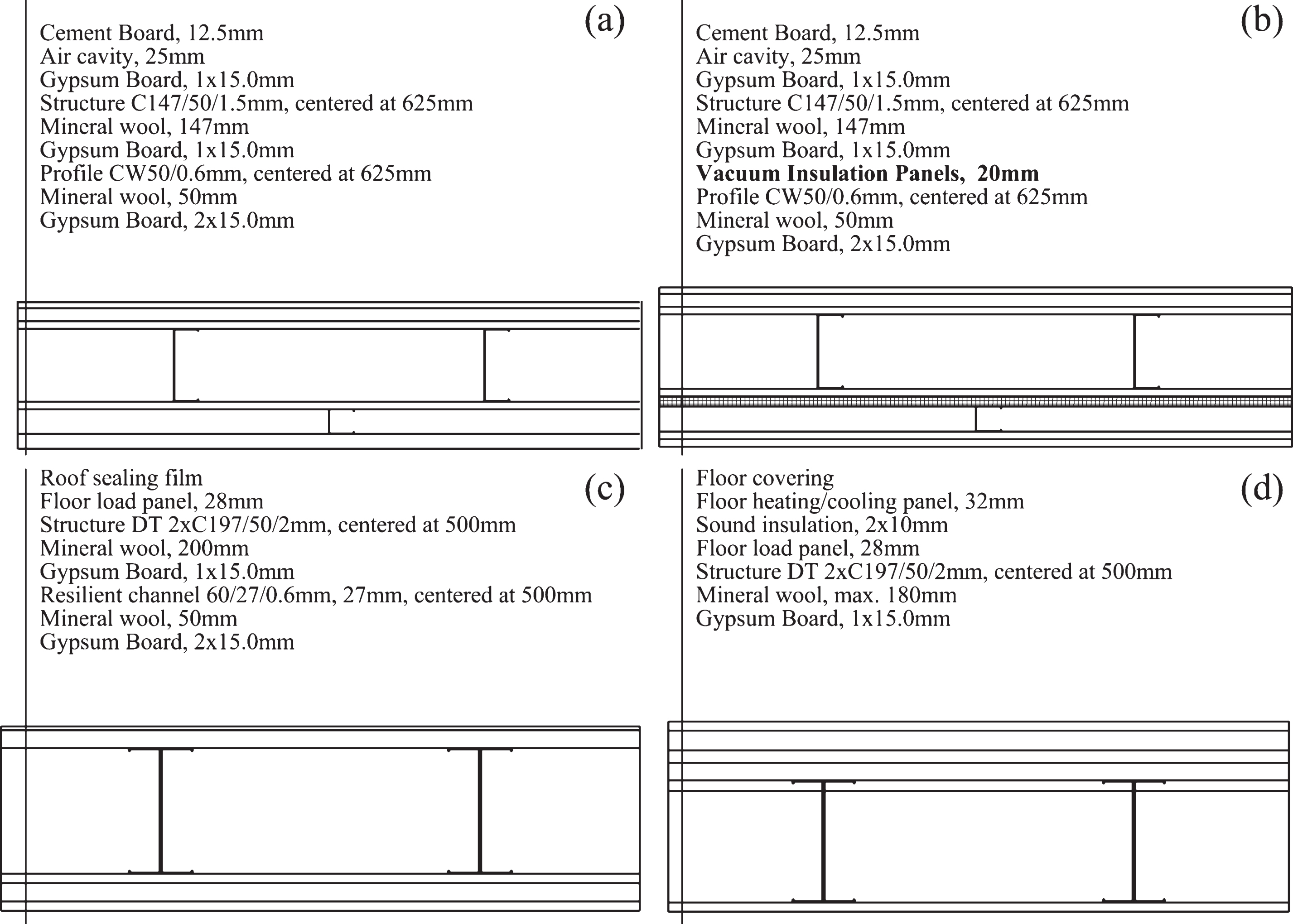
Fig.2
Partitioning of building into 1D, 2D and 3D geometrical models.
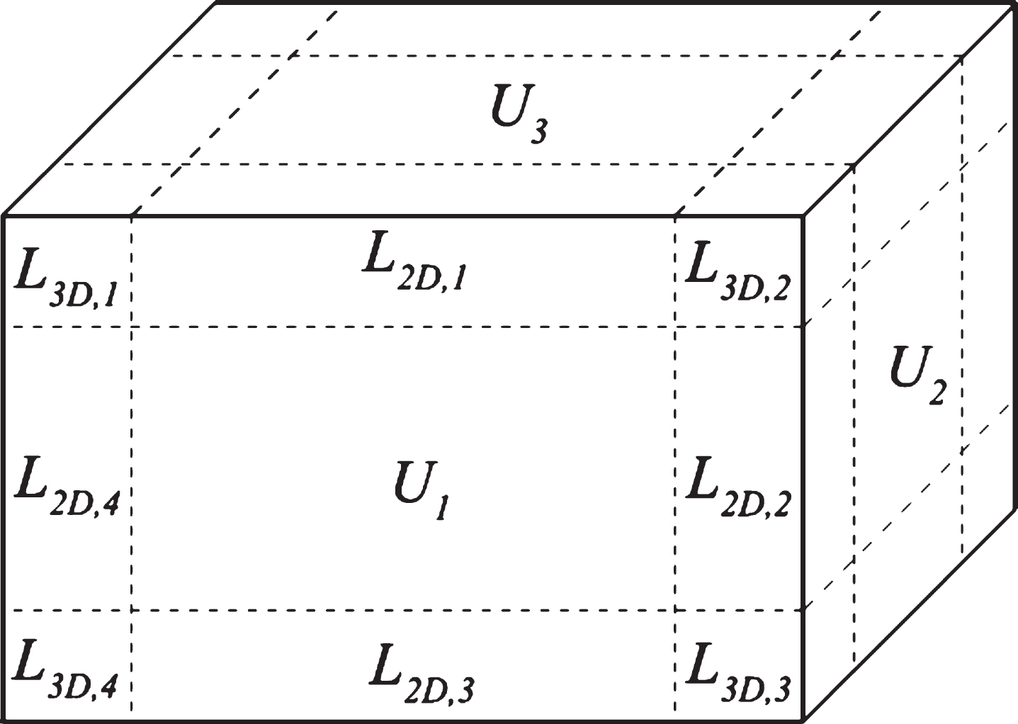
Fig.3
a) Temperature contours of the external wall for all the types of the studs without and with the VIPs and b) impact of the studs on the U-value for all the building elements.
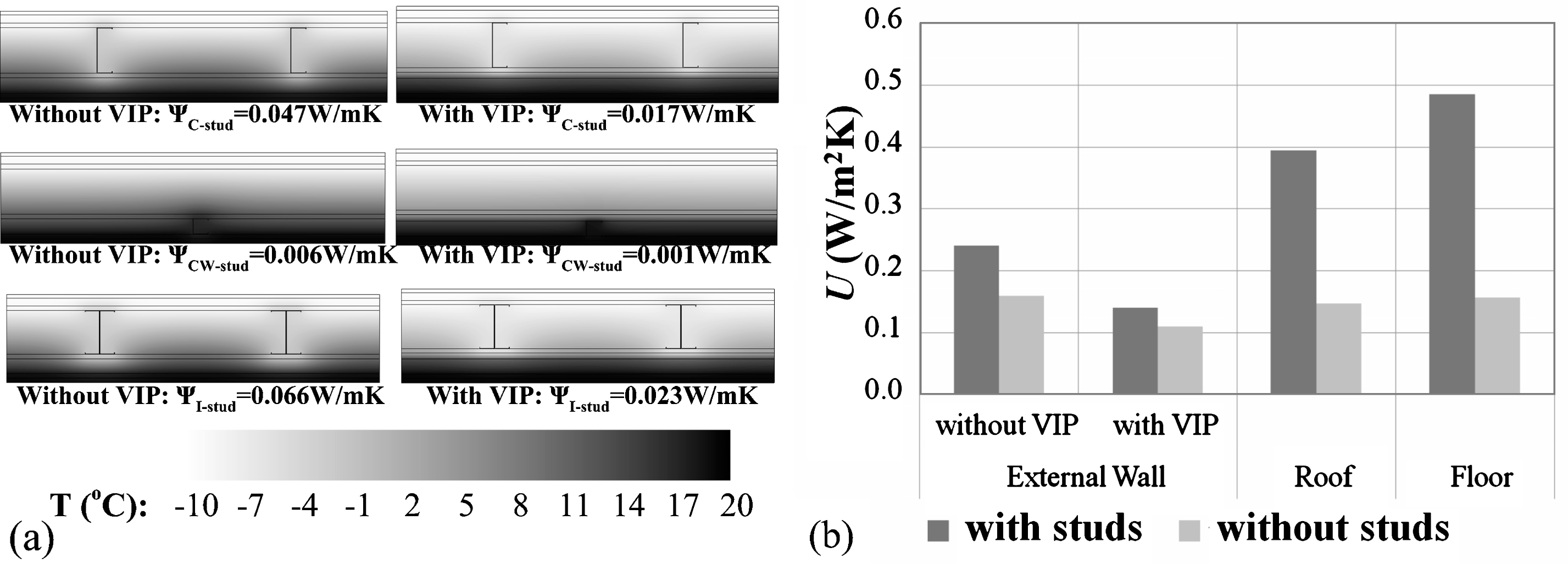
Fig.4
a) Temperature contours of the external wall – external wall junction without and with the VIPs, b) linear thermal transmittance for the 2D junction affected by the VIPs and c) linear thermal transmittance for the 2D junction not affected by the VIPs.
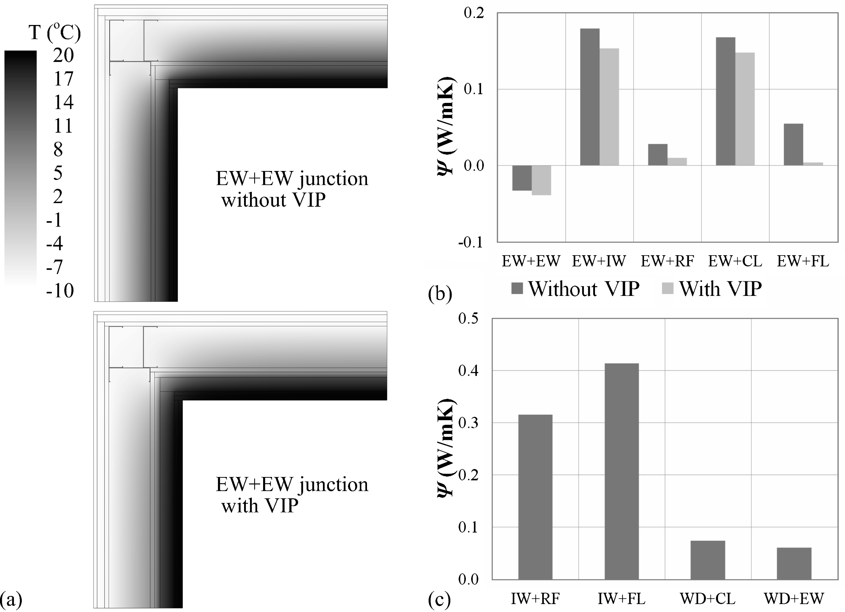
Fig.5
a) Temperature contours of the external wall – external wall – roof junction without and with the VIPs and b) point thermal transmittance of all 3D junctions without and with the VIPs.
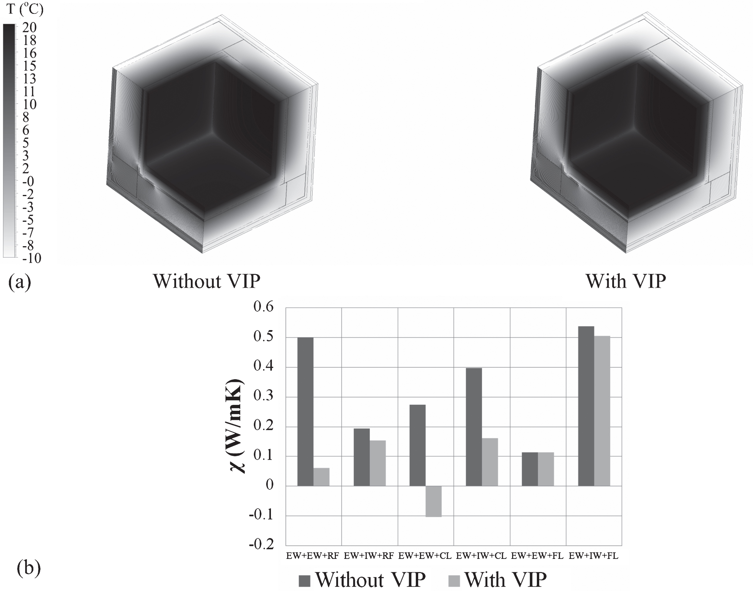
Fig.6
Impact of thermal bridges on the overall thermal transmittance without and with the VIPs.
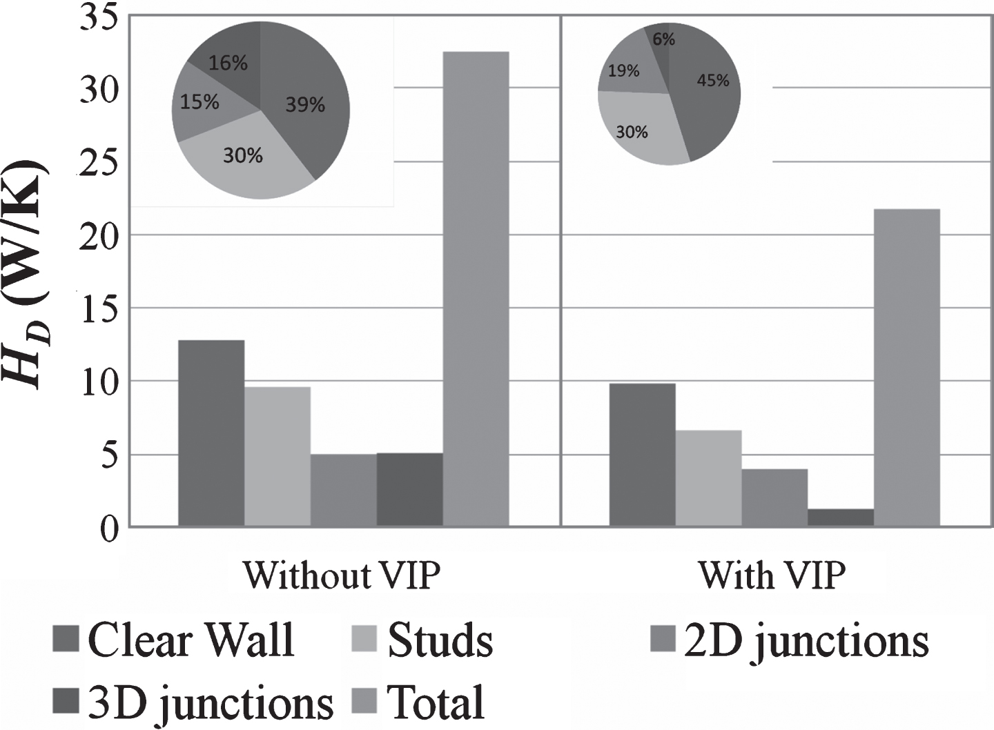
Fig.7
Design modification of the roof configuration: a) schematic diagram of the wall assembly with different thicknesses for the resilient channel, b) schematic diagram of the wall assembly with an XPS layer on the top, c) U-value of the wall assembly for different types of insulation and d) linear thermal transmittance of the wall assembly’s studs for different types of insulation.
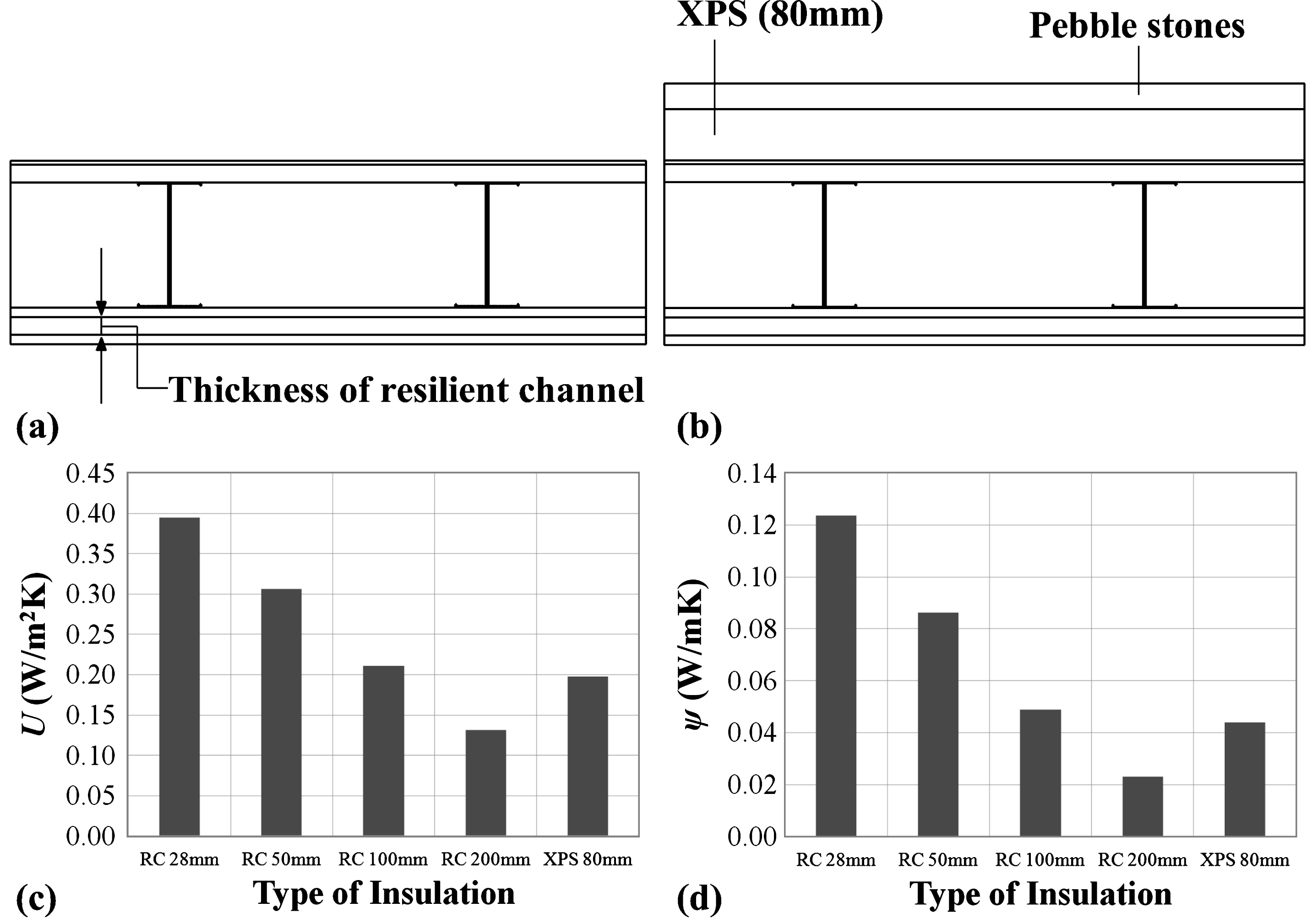
Fig.8
Design modification of the floor configuration: a) schematic diagram of the wall assembly and b) U-value of the wall assembly and linear thermal transmittance of the wall assembly’s studs for different thickness of EPS between the foundation and the soil.
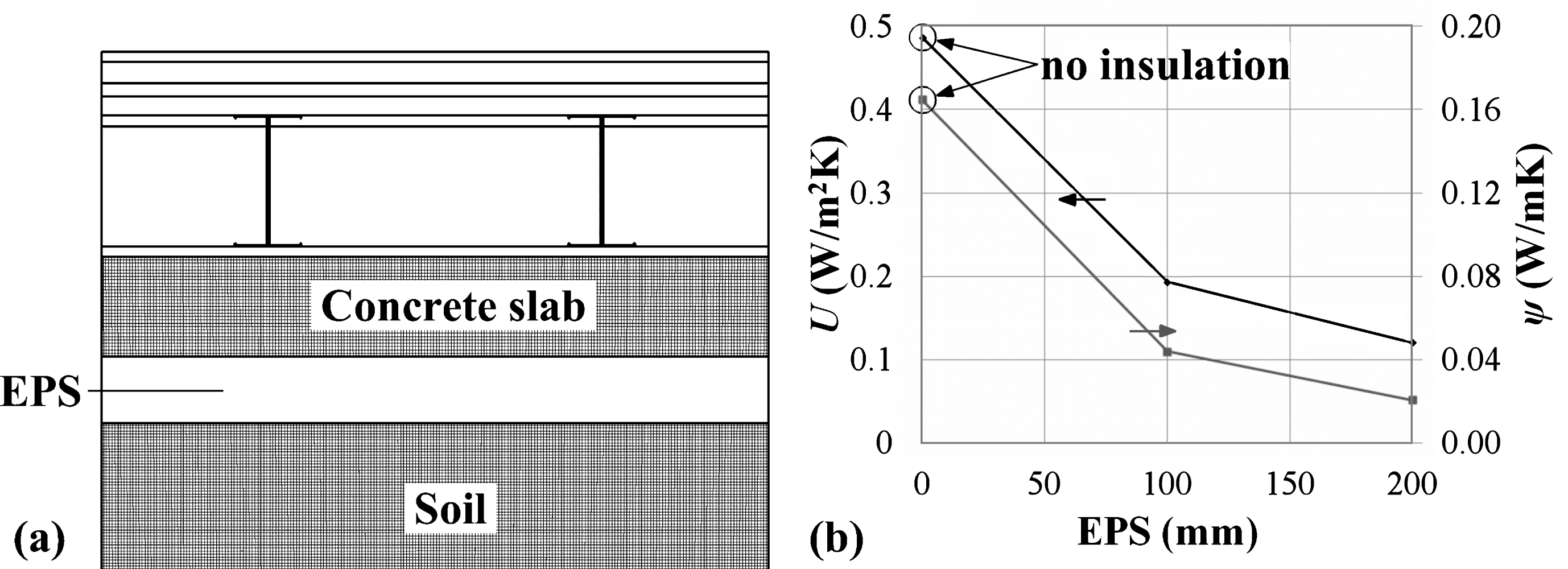
Fig.9
Design modification of the external wall – ceiling junction: a) schematic diagram of the junction and b) linear thermal transmittance of the junction with different SIM protection.
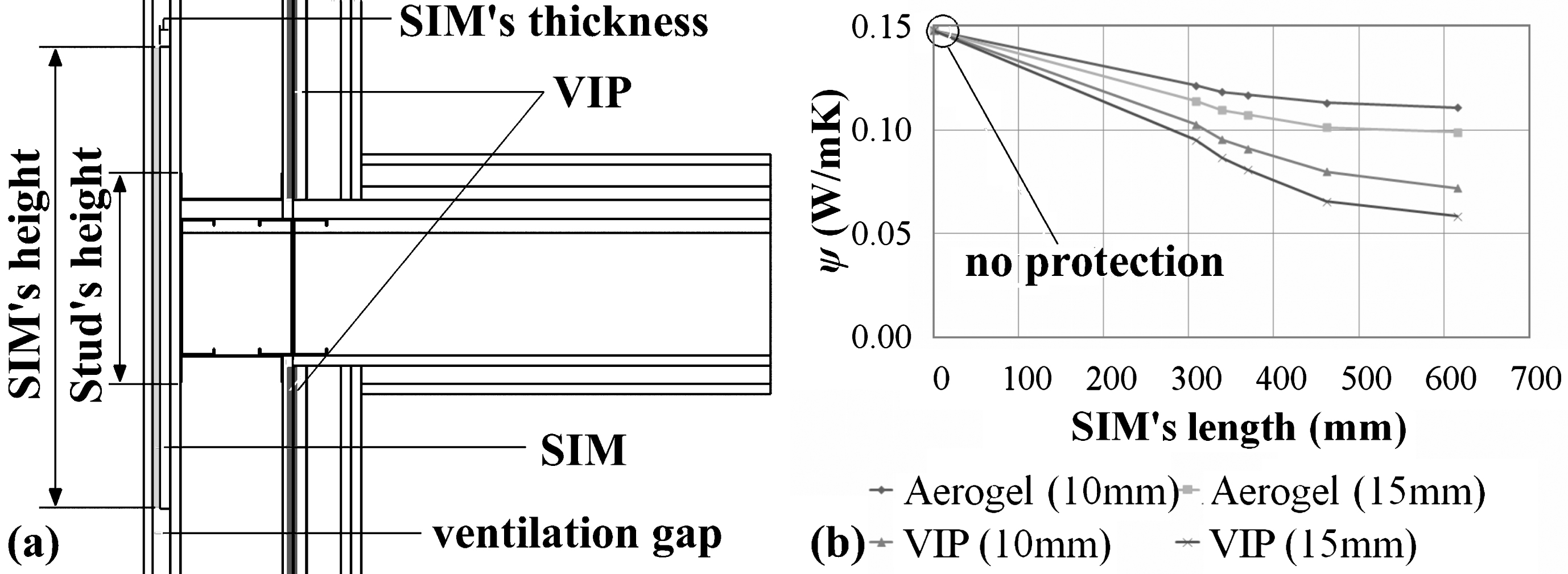
Fig.10
Design modification of the external wall – internal wall junction: a) schematic diagram of the reference junction, b) schematic diagram of the modified junction and b) linear thermal transmittance of the two design solutions.
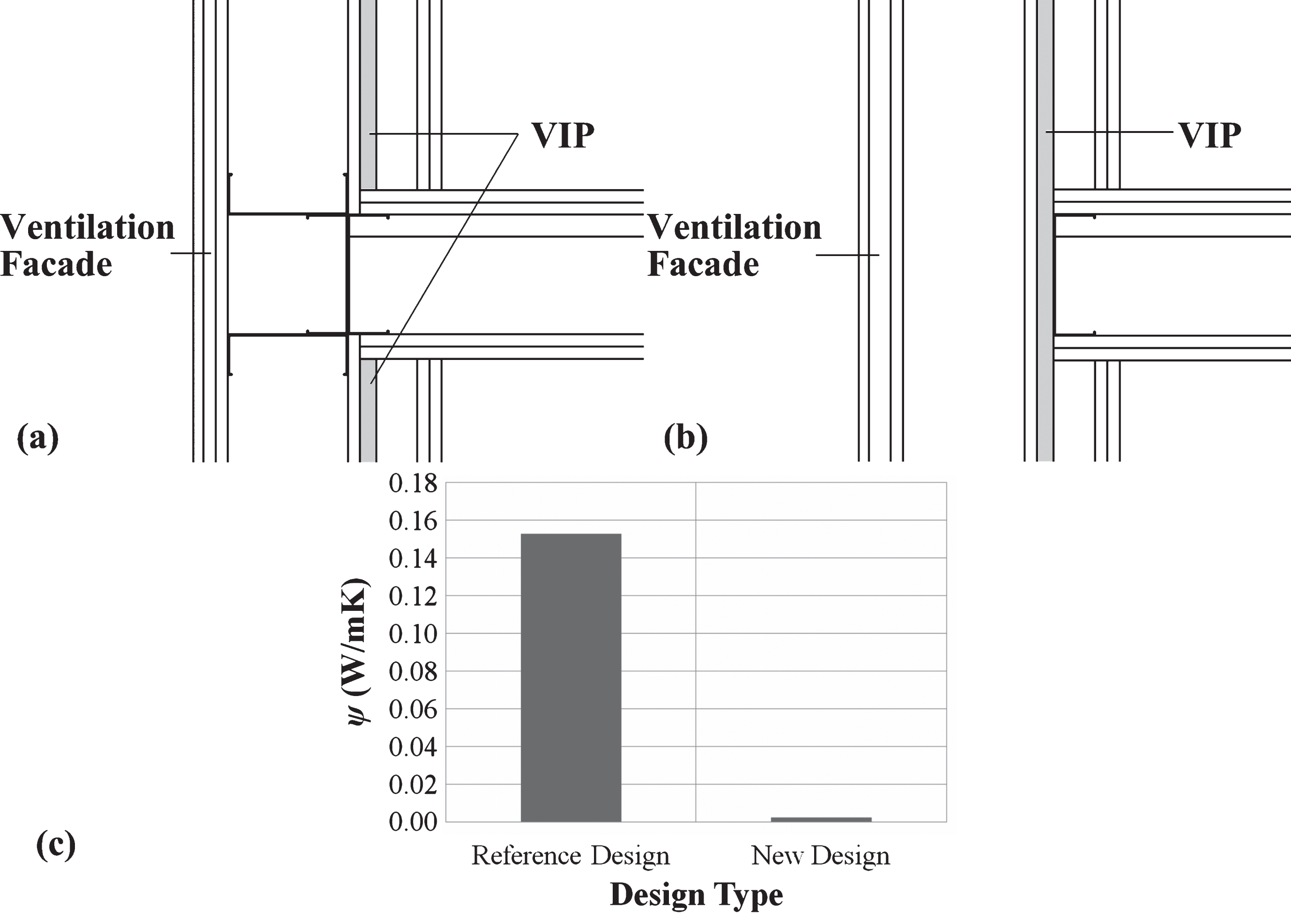
Fig.11
Overall thermal transmittance of the building with different design solutions.
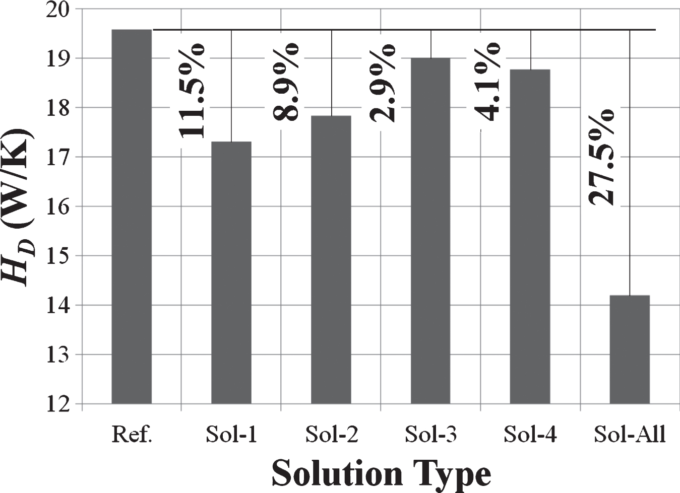
Table 1
Physical properties of the materials
| Material | Thickness d (mm) | Density ρ (kg/m3) | Thermal Conductivity k (W/m K) | Specific Heat Capacity Cp (J/kg/K) |
| Boards and Panels | ||||
| Cement Board | 12.5 | 1150 | 0.35 | 1000 |
| Gypsum Board | 15 | 1033 | 0.27 | 990 |
| Sound Insulation | 10 | 250 | 0.07 | 2100 |
| Floor load panel | 28 | 1500 | 0.44 | – |
| Floor heating/cooling panel | 32 | 1500 | 0.38 | – |
| Insulation | ||||
| Mineral wool | 23/50 | 0.035 | 850 | |
| VIP | 20 | 195 | 0.007 | 800 |
| XPS | 0.035 | |||
| Structural components | ||||
| Structure C147/50/1.5 | 1.5 | 7854 | 60.5 | 434 |
| Profile CW50/0.6 | 0.6 | |||
| Structure DT2xC197/50/2.0 | 2.0 | |||
| Resilient channel 60/27/0.6 | 0.6 | |||
| Other | ||||
| Roof sealing film | – | – | 0.2 | – |
| Floor covering | – | 2000 | 1.5 | 1000 |
| – | 1200 | 0.17 | 1400 | |
| Concrete | – | 2300 | 1.95 | 900 |
| – | 2300 | 2.3 | 1000 | |
| Soil | – | 2000 | 2.0 | 1000 |
| Ceramik tile | – | 2300 | 1.3 | 840 |
Table 2
Design solutions for decreasing the thermal bridges
| Solution | Description |
| Ref. | Reference building with VIPs at the internal side of the external walls |
| Sol-1 | Installation of an XPS insulation layer (80 mm thickness) on the top of the roof |
| Sol-2 | Installation of an EPS insulation layer (100 mm thickness) between the foundation cement and the soil |
| Sol-3 | Installation of a VIP strip (616 mm length – 10 mm thickness) inside the ventilation facade near the external wall-ceiling junction |
| Sol-4 | Decoupling of the external wall-internal wall junction |
| Sol-All | Implementation of all the solutions (i.e. Sol-1 to Sol-4) |


