Innovations in dynamic architecture
Abstract
High performance adaptive solutions are capable of responding to the dynamic nature of users and context. These innovative and dynamic systems are steadily gaining ground over ubiquitous ‘best fit’ static models. These architectural elements often exist beyond the scope of mainstream building standards and traditional methods for data representation or communication. This presents major challenges to a highly standardized and compartmentalized industry in which ‘innovation’ is limited to a few signature practices that design iconic yet expensive structures, which often prioritize aesthetics over performance. This paper offers an overview of the benefits that integrated dynamic systems bring to buildings. Through an examination of an applied practice, this paper offers guidelines for communicating complex geometry in a clear design language across interdisciplinary collaborations. The use of diagrammatic grammar to translate underlying algorithmic rules into instructions for design allows complex, innovative solutions to be realized more effectively. The ideas presented here are based on the design principles of the competition-winning scheme of the Al-Bahr Towers. As lead consultant in Innovation Design & Research at AHR (former Aedas-UK), Abdulmajid Karanouh designed and spearheaded this project in close collaboration with Arup. The buildings won the Best Innovation Award 2012 by the Council for Tall Buildings and Urban Habitat (CTBUH). The pair of towers won recognition for its performance-driven form, and dynamic facade that operates following the movement of the sun.
1Prologue
An architect should be a catalyst for positive change in the nature of buildings, cities and if possible our lives. In order to achieve this it is necessary to consider the entire context of architecture and to nurture innovation. In a summary of his speech at the Bartlett International Lecture Series, Wolfgang Rieder commented: “Architects are degenerated into beautifiers of buildings and not involved into the whole process. The focus is on appeal rather than functional innovations and smart design.” (Rieder, 2013) The ideas in this paper can be seen as a road map to reverse this trend.
There are many factors that influence architectural aspirations. Both governmental and public sectors demand increased performance, and improved efficiency. Environmental concerns and global economic difficulties require innovative solutions being created with ever diminishing resources. The world is rapidly changing. Our ideas and creations should change as well. Dynamic facades can change to provide optimal performances in relation to their environment. As Ziona Strelitz comments, “The static ‘best fit’ approach to facade design falls short of the optimum performance that could be attained relative to changing climatic conditions outside buildings. Dynamic facades that are able to respond to such changes may therefore become common place.” (Strelitz, 2005)
Architectural designs must address many challenges, from user-comfort, to efficiency, deliverability and sustainability. Dynamic architecture is capable of automated responses to external sources of data in order to achieve high performance systems. This is a new and challenging idea to an industry where static is the standard. Such innovations are especially challenging considering the fragmented nature of the AEC discipline. There are many industries involved and a changing roster of stakeholders on each project. As a result there is no standard for communication of ideas or data. In light of these challenges, the economy of value often outweighs the efficiency of performance.
Innovation is not a new concept. In architecture however it is an uphill battle. To make this process plausible it is necessary to communicate clearly and have stakeholders invested in the process. As the complexity of geometry increases so does the challenge of maintaining cohesive collaborations. Non-standard solutions can push interactions past the breaking point and put a project at risk. This research illustrates how clear communication of design principles was used to develop non-standard solutions in a multi-disciplinary environment. These guidelines can be a compass to guide architectural ideas through the phases of a project, so that the idea adapts to its context while maintaining its integrity.
The design of dynamic systems benefits from the introduction of rules-based algorithms. An increasing number of software developers, programmers, BIM managers, and computational specialists are being integrated into the development and delivery process in order to extend the capabilities of these tools. In a description of his course at the European graduate school, Achim Menges comments that “the increasing ubiquity of digital processes, the erosion of established disciplinary hierarchies of design and the rapid change of industrial logics of production has forged new alliances between the fields of design, engineering and natural sciences, leading to novel multidisciplinary and multifaceted design cultures.” (Menges, 2011)
While digital tools can make the conception of innovative ideas easier, they can add challenges when realisation is required. There are currently no recognized building standards or codes that describe how algorithms are developed, presented, and communicated across project-teams, contractors, and supply chain. There are no benchmarks to measure how innovative systems are tested and validated. There is no specification to compare an idea to if, for example, a design proposes a kinetic facade system that changes geometry and colour in relation to variable parameters like light, wind, and temperature. It could be argued that building codes and standards are not prescribed specifications, but rather held up as a minimum performance requirement to be achieved.
In light of this practice, innovation is often left to system developers and manufacturers who allocate considerable resources to develop ‘standard products’. Otherwise the remaining disciplines in the AEC industry are reluctant to invest in innovation. This is partly due to lack of guidelines that establish methods for development, communication, and delivery on a project level in an efficient and reliable method. To bridge this gap, tools and techniques are adapted from other high-tech industries. AEC is learning from aerospace and automotive sectors how to manage design development in order to overcome inefficiency and deliver innovative solutions in a more streamlined way. This idea is confirmed in Concurrent Engineering (Tookey, Bowen, Hardcastle & Murray, 2005) where the authors commented that “[…] construction should come closer to manufacturing in design, development and supply chain practices to achieve ambitious improvement targets.”
One technique is ‘Simultaneous Engineering’ in which product development stages run simultaneously. Another technique develops method statements in the form of storyboards and diagrams to communicate the principles that underlie an idea. This process helps interdisciplinary teams visualize a process more tangibly. An example of this is demonstrated in the 2012 BBC Documentary How to Build a Submarine produced by Tina Fletcher. The AEC industry would benefit from an established method of communicating design principles to help develop system innovation in multi-disciplinary environments.
This paper offers an overview of the potential benefits that integrated dynamic systems can bring to buildings. It also explores the means by which these systems are communicated throughout development. In the case study presented, the methods used to communicate underlying design principles were crucial in efficiently delivering the complexity of the geometry. In these situations the communication methods must be designed to avoid locking down the development and delivery process to abstract language or technology, therefore maintaining the intent while reaching out to a wider audience.
The ideas presented here are based on the design principles of the competition-winning schemeof the Al-Bahr Towers. As a Lead Consultant in Innovation Design & Research at AHR (former Aedas-UK), Abdulmajid Karanouh designed and spearheaded this project in close collaboration with Arup. The buildings won the Best Innovation Award 2012 by the Council for Tall Buildings and Urban Habitat (CTBUH). The pair of towers won recognition for its performance-driven form, and dynamic facade that operates following the movement of the sun. To realize this complex project across diverse disciplines, a set of instructions was developed to communicate the principles of Construction, Operation, and Design Execution (CODE). These principles were formulated into a single accessible document not tied to any specific software or industry.
The idea of the CODE was inspired by nature’s DNA – a set of instructions of what and how to build a human body and its functions – and by LEGO toys manuals. This paper offers a holistic understanding of the thought process that led to the Al-Bahr Towers facade design and delivery.
2Al-Bahr Towers. The Abu Dhabi Investment Council New HQ
2.1Project overview
The Al-Bahr Towers – the Abu Dhabi Investment Council’s New Headquarters – was an international competition won by Aedas-UK (now AHR) in Collaboration with Arup in 2007. The 150 meters high twin towers, shown in Figure 1, are located in Abu Dhabi, United Arab Emirates. Among the many performance-driven design features, the building stands out with its fluid form, honeycomb-inspired structure, and its automated dynamic solar screen. This system kinetically responds to the sun’s movement and offers the building its distinct identity.
2.2Competition brief
The following extract from the competition brief outlines the goals of the project.
“The building should reflect its prestigious status, contribute to the surrounding environment and take into account the architectural heritage of the UAE and Abu Dhabi in particular. A contemporary building utilising modern technology is required which should be recognized as one of the landmarks associated with the city of Abu Dhabi.” (Oborn, 2013)
The early intention was to seize this opportunity to create a ground-breaking building while realizing a more efficient vision of communication across disciplines. As a team we began to search for geometric forms inspired by the context. We looked to nature to find functional design principles where forms adapt to local environments. We drew inspiration from traditional technology proven over centuries to produce comfort in the desert. All these ideas began to drive the form-finding process. They were the source of the architectural definition and the root of the performance principles. Though born from simple inspirations our ideas grew ambitious and architecturally complex. The next challenge faced was how to clearly communicate our ideas to others.
The concept development of the Al-Bahr Tower was not linear but rather shaped like the number ‘8’. As a team we found ourselves repeatedly circling back to the starting point. The same was true of our approach to the document used to communicate the ideas. This new way of communicating design principles through genetic instructions and Lego Like diagrams evolved in cycles as often as the building. The CODE became a living document that kept communication clear and ensured stakeholder integration. This proved to be effective because the ideas were transparently documented as a process. All parties understood the design thinking that created the geometry rather than just being familiar with the latest set of CAD revisions.
The original task was to formulate a Geometry Construction Manual. This would have been an advanced geometry statement that would explain the build-up of the design. However, the complex nature of the mashrabiya, changing shape throughout the day, pushed this task well-beyond just communicating geometry. The CODE grew into something more than a manual. It became a document that, step by step, opened up the thinking process behind underlying design principles. This CODE became a machine to generate geometry and operational behaviour of the building. Any industry could build an exact model of the building with this set of instructions. Most interdisciplinary approaches to interoperability rely on an exchange of file formats. Through the CODE we built a framework for exchanging design principles. The original document comprised of nearly 600 slides, related, among many other topics, to the main form, supporting structure, internal finishes, and envelope. However, in order to give justice to the main topic of the paper, the following sections are limited to the facade mashrabiya.
2.3Site & Heritage
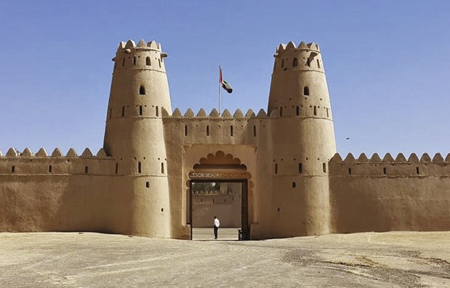
The location of Abu Dhabi is shown in Figure 2. It is arid and extremely sunny with temperatures and humidity reaching up to 49°C and 100% respectively during summer. The country’s architectural heritage is comprised of adobe buildings from the 19th century. Buildings such as the Al-Jahili Fort in Al-Ain, shown in Figure 3, have protective external walls surrounding an internal vegetated courtyard with watchtowers at the corners. The shapes of those towers are not perfect extrusions but have a rather cocoon-like shape. This is probably due to the fact that adobe is less robust than stone, causing the towers to be built wider as they reach the ground. The walls need little cleaning as the colour is that of the surrounding sand and dust. In Middle Eastern countries, fabric curtains and ‘mashrabiya’ (wooden lattice shading screens) are used to block direct solar rays, keeping interior spaces cool in the heat of the desert sun.
2.4Bio-inspiration
“To abstract ideas from biology and turn them into practical engineering solutions requires all disciplines to contribute.” (John, Clements-Croome & Jeronimidis, 2004)
To gather an interdisciplinary team around common design ideas we found references in nature to which we could all relate. From early on the intention was set to explore bio-inspiration. Guiding examples were drawn from the forms of cactus, pineapples, flowers and other natural systems. A cactus has umbrella-like features to protect its delicate weather-tight skin. Flowers open and close in response to changing weather conditions. The pineapple’s hexagonal envelope covers a double-curved surface efficiently. We sought to embody these attributes in the design of the towers.
2.5Philosophy & tradition
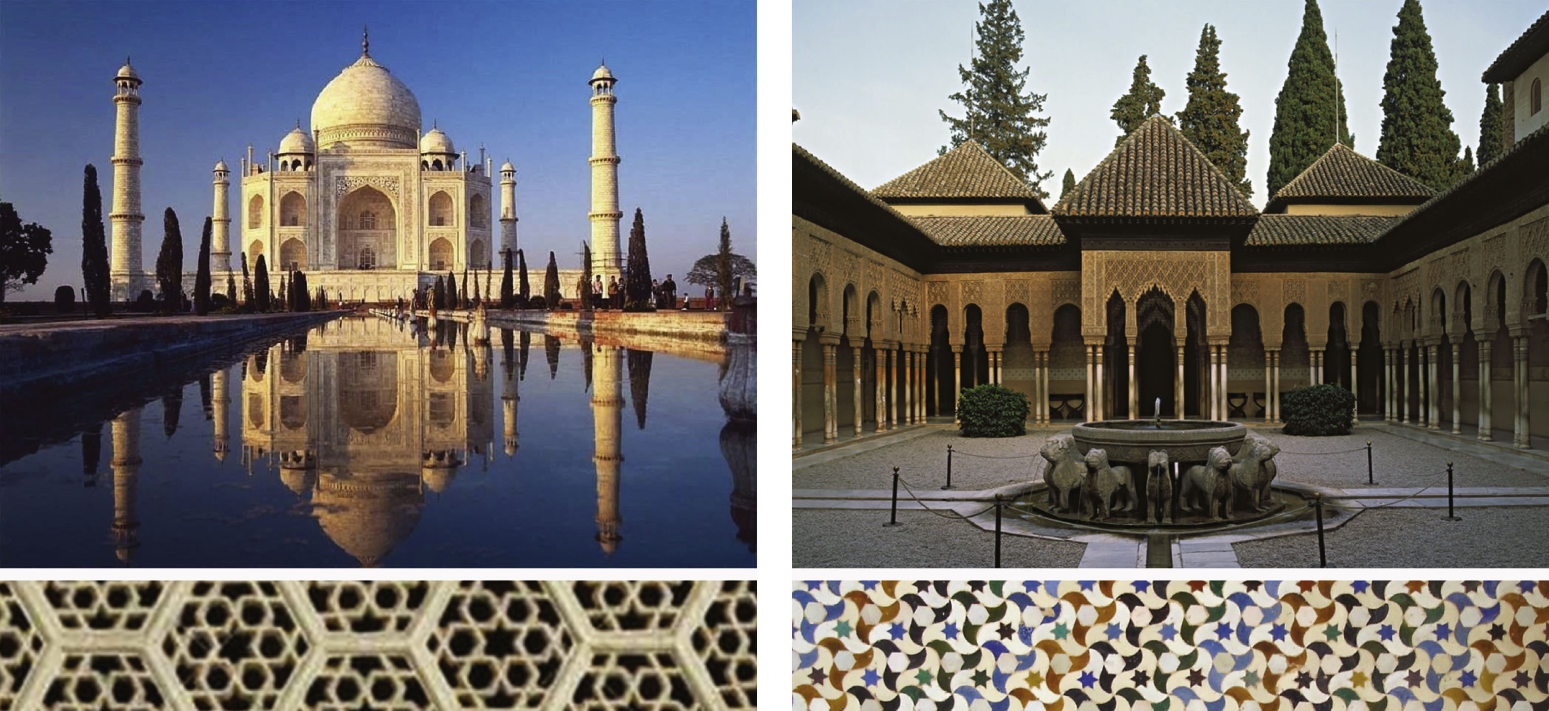
The beauty of Islamic Architecture can be found around the world, from Indonesia to Spain. The Taj Mahal in Agra – India (Fig. 4) and the Al-Hambra Palace in Andalusia – Spain (Fig. 5) are two of the New 7 World’s Wonders (www.new7wonders.com). The two buildings are different in form, colour, and style, and yet they share a common approach to design. Each implemented an underlying geometric principle from which every aspect was generated. This extends from the largest aspect, the massing of the form to the smallest detailed patterns of ornamentations. The majority of such underlying principles are generally defined by compositions of circles and spheres. These shapes represent the simplest expression of universal form. We find these shapes from the microcosm of the atom to the macrocosm of the galaxies. For the Design Team this idea of geometric language as a driver of designs both large and small became a compass by which to navigate architectural ideas. With this approach as a guide the Al-Bahr Towers became an integration of traditional and modern, as well as mechanical and digital. The Al-Bahr Towers draw inspiration from the past while looking forward into the future. In her writings on the Islam and Architecture, Sabiha Foster comments that, “Islamic architecture was always of its time; modern, hi-tech, revolutionary and forward looking. Centuries before computer-instigated geometry, through its knowledge of abstract mathematical symbols and their unifying relation to the various orders of reality, Islam aimed to relate the material world to its basic principle.” (Foster, 2004).
Islamic Architecture is all about context. The forms are found through optimizing performance. Excessive exposure to direct solar rays is mediated through the use of cooling courtyards, self-shading geometries and through patterns placed on both ceramic floors and wood shades. ‘Mashrabiya’ (Figs. 6 to 7) are made of geometric patterns providing shade whilst allowing sufficient diffused light and breeze into the building. They provide privacy as occupants can see outside while by-passers cannot see inside. The patterns fill a space with a unique sense of place as the shadows trace the path of the sun across the sky.
2.6Technology & automation
The Al-Bahr Towers reinvent these time-tested methods with modern technology and materials. To do this we used digital tools to automate design and execution. This has become established practice in high-tech industries like Automotive and Aerospace. Many of these techniques, including the use of algorithms, parametric design, Building Information Modelling (BIM), and production automation, have been integrated into the AEC industry. This has brought a higher degree of complexity to the creation and communication of architectural ideas.
During the competition stage of the Al-Bahr Towers, several design and engineering tasks needed to be carried out. These included form finding, developing supporting structures, incorporating MEP services, and integrating an innovative automated facade solution. All these tasks had to consider issues of context, nature, tradition, cost, programme and constructability. To achieve these goals and submit a competitive entry on time, it was necessary to carry out these tasks simultaneously. From the combined inspirations of natural systems and Islamic architecture we pre-rationalized the mathematical grammar and integrated the concept into design principles to guide the project. Through the CODE, these principles were developed into an explicit set of instructions as to how to generate the buildings geometry. Computational tools were then used to automate design and engineering tasks. This workflow was carried through until the realisation of the building. With the guiding principles of the geometry made explicit, the many programming/scripting, parametric modelling and advanced engineering analysis methods like Computational Fluid Dynamics and Finite Element Analysis could recreate the digital model to reach identical results.
This method ensured that error checking was efficient, as any deviation from the CODE principles could be found by spot-checking the model. Any discrepancy in geometry indicated that the design principles were not followed accurately. Then these errors could be tracked and corrected, using design principles rather than comparison of CAD models. Advanced computational design tools, if used properly, can empower design teams to deliver complex interdisciplinary projects. To deliver the Al-Bahr Towers, we built upon the foundation of knowledge gained from past projects, undertaken by the Aedas-UK’s R&D team. These large challenging projects like the Dubai Metro, gave us an appreciation for the ability of computational design tools to be used in rationalisation, iteration, and realisation of architectural ideas (Fig. 8). As complex projects evolve these tools implement changes in a model without manually rebuilding digital components.
2.7Concept
The design is driven from its context, taking into account environment, tradition, and technology (Fig. 9). This initial sketch illustrates the integration of these elements. While each design feature of the Al-Bahr Towers is infused with this balance, this article will focus on the dynamic facade.
Peter Oborn describes the beginning of the Al-Bahr Towers design: “We wanted to create a building which would set new standards of environmental responsibility, and began to explore the emerging form in order to study which parts of the building would require the highest levels of solar protection with the intention that we would then design some form of ‘Mashrabiya’ to screen these areas […]. The point of no return came one morning when Abdulmajid presented some sketches along with what looked at first like a clever piece of origami. The rest, as they say, is history … ”. (Oborn, 2013)
3Dynamic mashrabiya
The dynamic solar screen is a unique automated feature that is comprised of triangular units. Like origami umbrellas, these dynamic shading elements unfold to various angles in response to the movement of the sun in order to optimize the solar exposure of the facade. The dynamic folding geometry overcomes the limitations of traditional vertical and horizontal louvers when applied to complex buildings. The folding system transforms the shading screen from a seamless veil into a lattice-like pattern that, when necessary, provides either shade or light. This reduces solar glare, while providing better visibility by avoiding dark tinted glass and internal blinds that distort the appearance of the surrounding view. This system offers a better admission of natural diffused light. This reduces the use of artificial light and the associated energy costs. Reduced solar gain on the main skin results in reduced air-cooling loads, energy consumption and plant room size. The concept was inspired by blending the traditional shading screen of the Middle East with natural systems that adapt to the changing environment (Fig. 10).
3.1Envelope layers
The envelope of the building is made of a weather-tight glass curtain-wall and the mashrabiya dynamic solar screen. The curtain-wall is comprised of unitized panels with a floor-to-floor height of 4200 mm and a variable width of 900 mm to 1200 mm. From floor to ceiling the vision area of the curtain-wall spans 3100 mm. The innovative solar screen is spaced 2000 mm from the surface of the curtain-wall. The mashrabiya have stainless steel supporting frames, aluminium dynamic frames, and fibreglass mesh infill. Each umbrella-like device is assembled as a unitized system 4200 mm in height and varying between 3600 mm and 5400 mm in width. Each unit is sub-divided into six triangular frames that unfold through a centrally positioned actuator and piston. The largest unit weighs around 625 kg. Cantilever struts fixed to the main structure of the building protrude through the curtain-wall to support the dynamic units.
3.2Mashrabiya units distribution
There are 1049 units fitted to each of the towers covering the East, South and West zones. When a facade zone is subjected to direct sunlight, the Mashrabiya units in that zone will unfold into a closed state providing shading to the inner glazing skin. As the sun moves around the building each Mashrabiya unit will progressively open.
4Performance criteria
The goal of the dynamic mashrabiya solar screen is to block direct solar rays from landing inside occupied spaces during working hours, from 09:00 till 17:00. This reduces solar gain and controls solar glare. By responding dynamically to the changing environmental context, the mashrabiya has a major impact on the amount of natural daylight admitted into the building and reduces the cooling loads required for air-conditioning (Figs. 11–14). Benefits include increased visibility and privacy, a unique and iconic aesthetic, and overall quantitative and qualitative improvements to many aspects of the system. The following is a brief description of the performance criteria, driving factors, and related benefits that the dynamic mashrabiya solar screen system offers to the building.
4.1Solar gain & energy
Energy models evaluated the towers’ solar gains without external shading screens (Fig. 34). Theoretically, a shading screen should completely wrap the tower as direct solar rays hit the curtain-wall from all directions, especially during summer. The north face experiences direct solar rays only for a short time in the morning and later in the afternoon, i.e. before and after working hours. Shading units in the North zone was therefore unnecessary. With the MEP team, a maximum solar gain of 400 W/m was set for the curtain-wall and the shading screens were designed in front of zones that exceeded this limit. In the United Arab Emirates (UAE), 70% to 85% of the solar gain in typical towers is due to direct exposure to solar rays. The remaining is from direct energy exchange between internal and external environments. As a result there was not much value in having an expensive curtain-wall with very low conductivity; hence the overall U-value of the envelope was set at 2.0 Wm²/k. With Solar Gain and U-Value parameters set, further studies were carried out to explore opening configurations of the screen and optimize the number of folded units. This improved visibility and admission of natural diffused light (Fig. 15).
4.2Visibility & lighting
The target is to admit natural diffused light into the building and maintain a useful daylight threshold ranging from 250 to 2000 Lux throughout daily working hours (09:00 am to 17:00 pm). As soon as light sensors located at the perimeter of the ceiling near the curtain-wall read lower than 250 Lux, dimmers linked between the sensors and artificial lighting are activated to maintain the required comfort threshold.
4.3Wind
A series of wind-tunnel tests were conducted at various scales to anticipate the combination of loads exerted on the building generally and on the mashrabiya locally. Both small and full-scale models were tested accordingly. The tests revealed that the fluid form of the building generated relatively low +ve and -ve pressures, averaging 1.5 kPa up to a maximum of 3.5 kPa (Fig. 16). A single dynamic unit was later subjected to very high wind speeds up to 90 m/s, deployed in different opening positions, where the resulting pressures did not exceed the maximum figures applied on the building as a whole – due to the fluid aerodynamic geometry of the building form and dynamic mashrabiya system.
4.4Movement & tolerances
As the main supporting structure of the building perimeter is steel, floor-to-floor vertical and horizontal construction tolerance is minimal: ±9 mm vertical tolerance was allowed. The dynamic units are supported by cantilever arms 2000 mm from the frame of the building. Live loads (combined wind-loads and internal live loads) may cause vertical movements up to ±40 mm. The total vertical tolerance allowable for the dynamic mashrabiya units is up to 50 mm. The system is restricted from any horizontal movements. Horizontal construction discrepancies or building movements are absorbed by the flexibility of each dynamic unit’s structural frame.
4.5Durability & service-life
The main supporting frame of the system is designed to last for fifty years. Other components like actuators and bearings are designed for a minimum of fifteen years before requiring replacement. The system is designed to resist the following:
• High exposure to UV solar rays and atmosphere temperatures reaching up to 49 degrees.
• Humidity reaching up to 100% during summer.
• Corrosion – as the building faces the sea and is exposed to high levels of sand and dust.
• High wind-loads and wind speeds up to ±3.5 kPa and 240 km/h respectively.
• Impact and abrasion due to cleaning/maintenance activities and due to exposure to sand storms.
• Fire up to two hours for the main supporting frame, as it is comprised of heavy steel components.
4.6Materials choice
Each of the drivers played a role in the choice of materials for the building envelope.
• 1.4462 Duplex Stainless Steel: all main-fixed supporting components like cantilever arms, Y-structure arms, and brackets connecting the system back to the main structure are made of duplex stainless steel, due to its high strength and corrosion resistance. All exposed/visible components have shot-peen finish, similar to sand blasting. This camouflages dust and sand particles that settle on the steel surface.
• PVDF coated Aluminium: all curtain-wall and fabric mesh frames are made of extruded aluminium profiles. These achieve a finer level of detail than possible with steel. It is robust, lightweight, and corrosion resistant, and elegant looking when finished, in this case in a champagne colour, as it resembles the beige colour of local sand.
• Glass: curtain-wall vision glass is made of DGU of 40% visible light transmission, 0.28 G-Value and 18% external light reflectance.
• Teflon: All bearings and joints separators are made of marine-graded Teflon components.
• Silicon: All sealants/gaskets are made of black silicon – especially highly resistant to UV rays and other weathering factors.
NOTE: The solar gain and energy studies were intentionally left uninfluenced by the mashrabiya. The geometric definition and opening configurations were then optimized to improve lighting and visibility.
5System components
The mechanism of the unit is driven by a centrally positioned electric screw-jack linear actuator that operates on very low energy consumption. Each actuator uses less energy than a regular light bulb. The actuator stroke reaches up to 1000 mm, which folds the mechanism and provides up to 85% clear opening area. All mechanical connections comprise of marine-grade Teflon bearings.
5.1Single mashrabiya dynamic unit key components
The following describes the key elements and components that make up the mashrabiya system (Fig. 17):
1. Power & Data: electric and data feed cables passing through the facade.
2. Strut-Bracket (SS): connects to main structure
3. Cantilever-Strut (SS): hooks on the Sleeve
4. Star-Connection (SS): receives the Y-frame ends
5. Actuator-Casing (Aluminium)
6. Hub (SS): joins the Y-frame and Actuator together
7. Sleeves (SS): connecting Y-frame to H
8. Y-frame (SS): supports the whole mechanism
9. Node-Pin (SS): pins to star-connection
10. Mobile-Tripod (Aluminium): supports the fabric frames
11. Actuator Head Pin-Connection (SS)
12. Stabilizer (SS): relieves the actuator shear forces
13. Slider (SS): allows tripod to travel along the Y-frame
14. Fabric Mesh Frame (Aluminium)
15. Fabric Mesh (PTFE Coated Fibre Glass): infill material
16. Ball-Joint (Teflon): joins frame corners.
5.2Control software
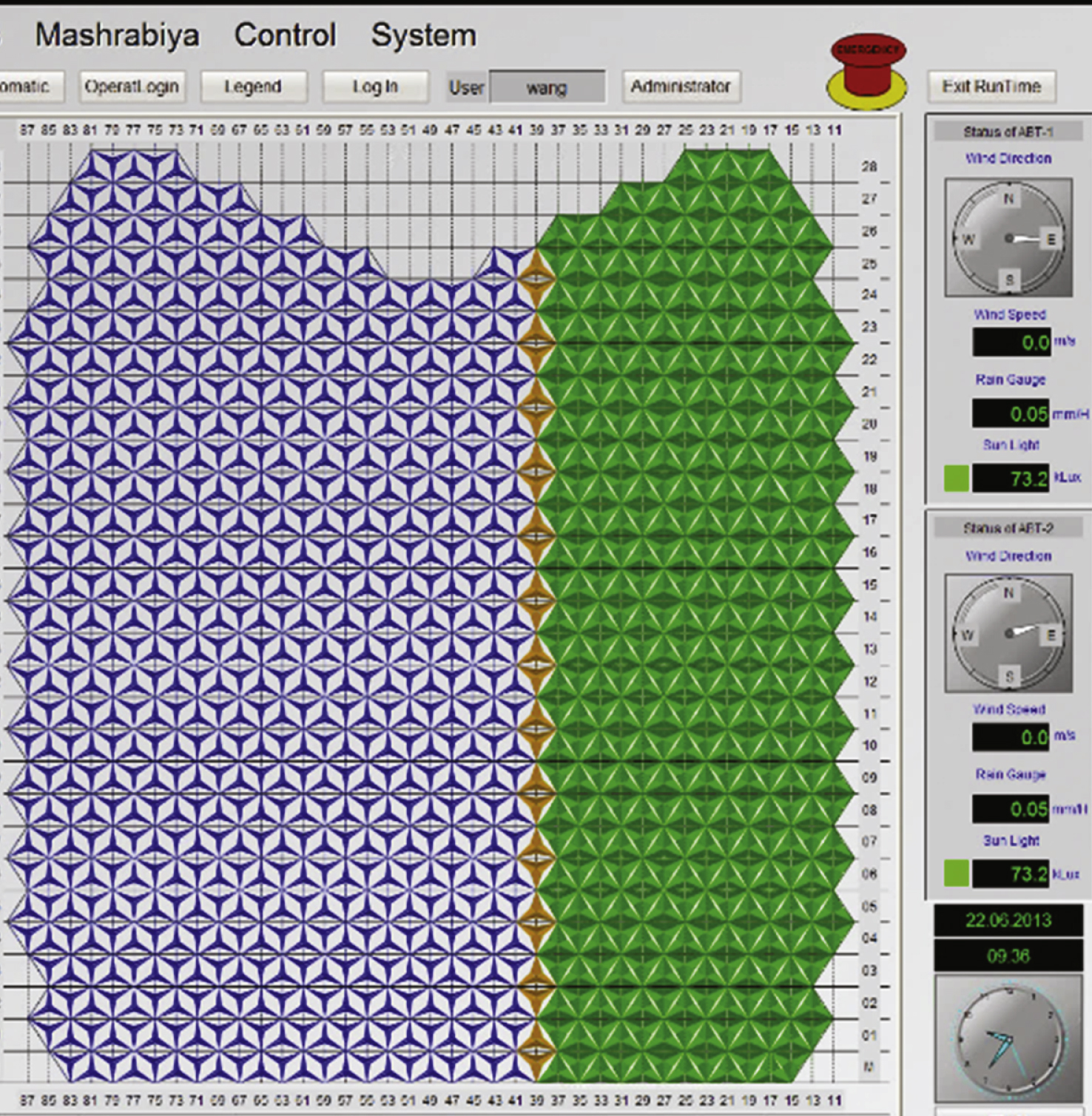
Siemens’s well-established platform was used to develop the control software and Human/Machine Interface (HMI) of the Al-Bahr Towers dynamic solar screen (Fig. 18). An embedded pre-set programme simulates the movement of the sun and deploys the mashrabiya units in corresponding folding configurations. The HMI allows manual intervention of the operator in case of emergency, maintenance requirement, or for ceremonial/demonstration purposes. Each unit has a unique location and ID on the screen, which is linked to positioning sensors located in the actuator of each unit. The software is linked to three main sensors located at the top of each tower; 1) light 2) wind and 3) rain. The system offers live feedback to the operator including wind speed, light intensity, rain levels, faulty units and their folding positions. This feedback is used to override the pre-set programme and to move the units into mid-fold position in the event of unusual conditions, like a storm.
6Benefits of the dynamic facade system
The following sections describe the benefits of this innovative dynamic facade system.
6.1Quantitative benefits
The following are measurable benefits of the innovative facade system.
• 50% energy savings for office spaces alone, and up to 20% for the building overall
• 20% reduction in carbon emission with up to 50% for office spaces use alone
• 15% reduction in overall plant size and capital cost
• 20% reduction in materials and overall weight due to the highly fluid, rational and optimized design
6.2Qualitative benefits
The following are non-measurable benefits of the innovative facade system:
• improvement of user-comfort and improved physical and psychological well-being of occupants
• the overall iconic identity of the building
• Better naturally lit spaces through better admission of natural diffused light (Fig. 22)
• Better visibility of external natural views, less use of obstructive and psychologically trapping blinds (Fig. 23)
• Improved comfort by reducing heavy air conditioning loads and air draft
• Provide the building with a unique identity, rooted to local heritage and environment
• Provide a unique and entertaining feature both to occupants and passing-by public.
7Key challenges
Although dynamic shading systems are not new, the development of the bespoke systems like the mashrabiya normally take place on projects of smaller scale where risks are easier to manage. In the case of the Al-Bahr Towers however, the Project Team faced a formidable combination of challenges.
7.1Bespoke design, programme & procurement
From a hardware point of view, there were no ‘off the shelf’ systems that could be bought from suppliers’ catalogues. Most dynamic systems are louvers that operate in only one direction. There was no reference building that we could compare with our system. Equally, from a software perspective there was no standard program that could carry out all the exercises and tasks to related geometry and performance. Neither resources, nor the fast track nature of the program, allowed for a development of a completely customized system. The Design Team had to find a balance between developing bespoke parts and writing new applications on one hand, and use existing established parts like Teflon bearings and commercial software like Rhino on the other.
7.2Cost
The design and construction of the Al-Bahr Towers involved the creation of a large scale bespoke solution that demanded careful design, engineering and optimisation in order to control costs. Any benefits, advantages or other justification, for every single element, was heavily challenged, based upon their associated cost and return value offered to the project. The pre-rationalized nature of the innovative dynamic facade, with its focus from the very beginning on a ‘design for constructability approach’ allowed the reduction of material waste. An average of 10% waste is common for regular buildings reaching up to 30% waste for bespoke buildings. The Design Team of the Al-Bahr was able to bring the level of waste down to 3% to 5% on this ambitious and complex project. The sharing of design principles through the CODE played a large role in this achievement.
7.3Balance
This project required a large number of experts and specialists. The iconic nature, technical challenge, fast track program and scale of the project meant that the role of architect, engineer, project manager and QS all had almost equal weight on the project. This fostered an intentional balance between functionality, aesthetics, quality and economy. The weight was redistributed with the main contractor and specialist contractors joining the Project Team later in the process. The management of this level of complexity required the development of techniques as unique as the mashribiya themselves.
7.4Process management
One of the greatest challenges was managing the design complexity. The complex geometric and technical nature of the building required an unorthodox and creative approach to manage the mass customized components and data associated with the dynamic nature of the facade. This challenge was compounded by the location of the teams throughout the world from the US to Japan, running through several European countries, the UAE, and China.
7.5Managing complexity
With thousands of unique components associated to the 4D design and functionality of the building and its envelope especially, implementing process-automation to manage mass customisation and associated performance and impact on programme and economy was essential.
7.6Testing & performance validation
As the Mashrabiya were an innovative solution critical to the performance of the building, they had to undergo rigorous testing regimes especially devised for this purpose. This included wind load testing: a full scale Mashrabiya unit was built in a wind tunnel at the CSTB facilities in Nantes, France and was subject to wind speeds up to 90 m/s in different folding positions. Another test in Basel, Switzerland studied the mechanism’s long term durability and reliability: a full scale Mashrabiya unit was built in a special chamber controlling temperature and humidity. The temperature was gradually brought up to 60 degrees Celsius and humidity reaching up to 100% while the Mashrabiya unit was regularly sprayed with sea-water, sand, and dust particles from Abu Dhabi and set to operate for 30,000 cycles–roughly equating to eighty years of real-time operation (Fig. 24).
8Design communication
One of the greatest challenges on a facade project of this complexity was how to communicate design principles. The process that generated the dynamic facade system was an intricate series of steps. Clear concise methods were required to explain these principles to a project team and supply chain that did not necessarily have an identical level of understanding regarding mathematic, computational, or parametric design. Simply handing over a digital model, computer code or parametric algorithm was difficult, considering the diversity of computer programs used across industries. The exporting of data between programs commonly results in data loss or corruption that is often difficult to detect. The complex form and changing geometry of the dynamic mashribya meant that it was also not sufficient to communicate through conventional drawings. It was at this point where it became necessary to devise a new way to communicate the Construction, Operation and Design Execution (CODE) of such a complex system. The idea of the CODE was inspired by both DNA – a set of instructions of what and how to build a human body and its functions – and from LEGO toys manuals (Fig. 25). The difference between the CODE on one hand and the DNA and LEGO manual on the other is that a) the algorithmic design principles, underlying rules and rationale behind the design are illustrated in the CODE, while in DNA and LEGO manuals they are not, and b) while LEGO manuals use illustrations and diagrams, they describe a fixed/closed design – not a parametric developable one like the CODE.
8.1Algorithmic thinking & Universal design
To drive a design by geometric principles and rules required the use of both abstract and explicit mathematics. With the geometric principles pre-rationalized, the process is not locked down to a single CAD/BIM Package or 3D model. In this project this offered every related party (architect, engineer, contractor etc.) the freedom to use whatever tools they were comfortable with to produce their scope within the specified tolerances. The complex nature of the geometry of the building and dynamic behaviour of the mechanized units meant that components would connect in numerous configurations. It was therefore very important to adopt a ‘universal design’ approach, where connections and interfaces would be designed to adjust to as many scenarios as possible. This limited the complexity associated to unique sizes while minimising the number of unique engineered solutions.
This approach lends itself quite well to parametric design. This includes various packages like Grasshopper, Digital Project (CATIA), Tekla, Inventor, and SolidWorks, among others. It allowed direct data extraction from digital models in order to control CNC machines for fabrication. Similar approaches were used to feed data to topographic survey machines on-site for coordination of installation. In total over fifteen different software packages were used by various parties. This was coordinated efficiently through the use of the CODE.
8.2Instructions for Construction, Operation, & Design Execution (CODE)
The CODE was key in communicating the design principles and geometric creation of the building and dynamic facade. The CODE allowed us to transfer ideas as to how the geometry blocked direct solar rays from inside occupied working spaces. By clearly communicating the principles that minimized solar gain and solar glare, while maximising the admission of natural light and unobstructed views, we were able to have all stakeholders buy into the importance of the unique architectural feature. It was this interdisciplinary consensus that allowed the idea to stand strong when challenged. Each industry had a clear understanding of the building envelope principles and their impact on related performance criteria. With the thresholds and targets clearly defined in terms of energy and lighting the design became more than an iconic visual element, it became an integral system for efficiency and high performance. The result of the CODE is that, in an industry as fractured as AEC, this project saw a deep understanding between the perspectives of diverse industries. This dynamic was transformative, and where meetings had the potential to become combative they often became truly collaborative. By clearly communicating design principles, issues could be addressed without compromising the idea.
This section offers an overview on how the design intent, philosophy, and performance criteria of the Al-Bahr Towers – described in earlier sections – were translated into underlying universal design principles that generated the geometry and operational behaviour of the building. It explains how these principles were formulated into a CODE document and communicated across the Project Team. The Al-Bahr Towers’ original CODE was comprised of nearly sixhundred slides covering many building items and systems. This section however will be limited to parts of the CODE related to communicating the design and operation of the mashrabiya.
The CODE content is summarized by the following sections:
1. USER GUIDE
• Introduction
• General Notes & Disclaimers
2. CODE GRAMMAR
• Content
• Instructions & Narrative
• Mark-up & Dimensions
• Objects including Points, Wireframes, Lines, Surfaces, & Solids etc.
• Diagrams
• Algorithmic Design Principles
3. CODE DEVELOPMENT
• Design Intent
• Design & Delivery Philosophy
• Concept & Key Building Elements
• Performance Criteria
• Underlying Universal Design Principles ← by undergoing Algorithmic Design Principles process
• Geometry Construction & Operation ← by undergoing Algorithmic Design Principles process
Section 1 USER GUIDE:
This section offers general guidance for the user in terms of clarification regarding the purpose of the document, owner, responsibilities, liabilities, and interfacing between various related parties.
Section 2 CODE GRAMMAR:
This section shows how to develop a diagrammatic oriented grammar to represent and communicate key building elements, components and related design principles. Guidelines for the creation of building elements are represented through CODE-specific principles. The resulting geometry driven points, lines, surfaces, and solids are identified by colour – similar to the CAD standards used to mark-up 2D, 3D, and 4D build-up diagrams. In this section principles are established regarding how to develop suitable algorithmic rules and parametric conditions. The CODE is used to formulate and apply underlying universal design principles to objects and geometries. It minimizes the use of abstract scripting, programming, mathematical language/symbols and software-specific commands. This is achieved through a process where the following phases are identified and completed for each described system to become functional and communicable: A - Context (working environment and platform) → B - Object (geometric object introduction by construction or mathematical function) → C - Constraints (parametric conditions applied to objects) → D - Transformation (manipulation and duplication of objects) → E - Automation (conditional ‘behaviour’ embedded into objects as a system).
Section 3 CODE DEVELOPMENT:
This section comprises of a series of narratives and illustrations explaining the design concept and development in a storyboard-like fashion so that the user understands the design intent and principles of the project. The following CODE examples will be focused on the last two points: Underlying Universal Design Principles and Geometry Construction & Operation, both of which are results of the Algorithmic Design Principles.
The following figures are examples from the CODE section that details the Mashrabiya panel (Fig. 26).
Figures 27–28 demonstrate the universal geometric principles that ensure seamless integration and synchronisation between form, structure, curtain-wall, and mashrabiya dynamic solar screen.
8.3Underlying Universal design principles
The following principles were used to communicate the projects design intent and performance objectives. By clearly stating these ideas to the interdisciplinary team it was possible to determine whether design decisions would be in line with the underlying intent of the project.
8.3.1Shading principles
As general rule of thumb, a shading element is most efficient when it faces solar rays directly i.e. orthogonally. A shading element must cast shadow of all its edges onto the adjacent shading element to avoid direct solar rays landing on the vision glass behind it. On one hand, however, the moving sunlight results in solar rays landing on the curtain-wall at infinite angles. On the other hand, not all direct solar rays travelling inside the building affect the overall performance of the envelope as long as they are limited to a buffer zone around the perimeter of each floor-plate without landing on the working desk level and in the eyes of occupants (Fig. 29). Both experience and early shading studies using various opening configurations of the mashrabiya screen resulted in developing the following principles to control the shading elements performance:
- The configuration of the shading is based on optimized categorisation of solar rays.
- General solar rays landing at angles between 0 and 79 degrees onto the curtain-wall surface requiring full front-cover of the curtain-wall – this is achieved by an un-folded configuration.
- Intermediate solar rays landing at angles between 80 and 83 degrees onto the curtain-wall surface requiring partial front-cover of the curtain-wall allowing partial unobstructed views – this is achieved by a mix-folded configuration.
- High solar rays landing at angles higher than 83 degrees onto the curtain-wall surface requiring no front-cover of the curtain-wall allowing maximum unobstructed views – this is achieved by a fully-folded configuration.
8.3.2Geometry retention principle
The geometry must avoid major twisting, bending and stretching of components while going from one opening configuration to another in order to reduce risk of rattling and low frequency vibration that can tear the system apart especially at high levels. This is the reason behind adopting an origami-like folding solution where all components retain their geometric characteristics.
8.3.3Triangulation principle
In addition to its structural robustness and foldability advantages, the triangular shape of each dynamic mashrabiya unitized unit meant that it sits on any geometrically complex surface without having to use any on-site cold bending or stepping to fit one dynamic unitized unit next to the other.
8.3.4Robustness principle
The default Un-folded position is created with a fold in order to ensure the system did not move towards the opposite direction. This provided enough robustness to withstand higher wind-loads during windy/stormy days.
8.3.5Integration principles
All key building elements like form, structure, and envelope integrate seamlessly, as all related components interface with one another following consistent conditions through pre-rationalized underlying universal geometric rules. These rules apply consistently from macro to micro scale. This is achieved by embedding 2D and 3D underlying grids and component-to-grid relationships that determine the geometry and coordinates of all components parametrically. Various elements-representative layers are generated from each floor plate vertically and horizontally following such rules. These layers intersect with various radial grids – numbered and labelled depending on which building element they belong to – to generate point-cloud nodes that belong to each element. Special geometric rules devised for each element connect the nodes together to generate components-representative wireframe lines.
8.3.6Automation
The following automation conditions are extracted from Opening Configurations Principles:
If solar rays land on the curtain-wall between 00 and 79 degrees → Un-folded configuration
If solar rays land on the curtain-wall between 80 and 83 degrees → Mix-folded configuration
If solar rays land on the curtain-wall greater than 83 degrees → Fully-folded configuration
Figures 30 and 31 illustrate the mashrabiya dynamically reacting according to these principles during a solar simulation.
9Feedback from use of the CODE to communicate design principles
The CODE document was formulated in-house at Aedas-UK and issued to all parties involved in the design and delivery process. Every party that received the CODE document and associated 3D reference model was asked to reproduce their own related information using their own tools and software following the CODE instructions to the specified tolerances. Gehry Technologies was hired as BIM Specialist Contractor to integrate the models from various parties into one comprehensive BIM model and exercise clash detection to verify the accuracy of each model accordingly. It should be noted however that, in parallel, every received industry specific model was also checked by an inspection process at Aedas-UK. The use of the CODE made clash detection much more efficient. Every rebuilt and verified model was owned by the individual author. This gave the diverse interdisciplinary teams the confidence that decisions were not based on unverified information. This ensured that a diverse group of stakeholders would not be at risk of communication errors based on interoperability between software. For an ambitious award winning project such as the Al-Bahr Towers (Figs. 32–34) this approach proved to be a key asset in collaborating efficiently and keeping stakeholders in sync. The CODE proved itself to be a high quality means of documenting design principles. This added value to the project and resulted in a greatly reduced number of requests for information during construction.
The following feedback was received from key players who witnessed the development and implementation of the CODE as well as its use in the design and delivery of the Al Bahr Towers. These comments were transcribed from evaluation interviews post project completion. This feedback provides a perspective on the utility of the CODE document.
Alain Anthony – Director of Design, Yuanda
• Role: Led the system design development and manufacturing process of the curtain-wall and mashrabiya.
• Background: Alan is considered by many people in the facade specialist contracting industry as one of the best facade system designers in the business, having designed the facade system of major iconic projects around the globe. Alain worked for leading facade specialist contractors including Permasteelisa - Gartner and Schmidlin. Some key projects that Alan worked on include Foster’s ‘Gherkin’ and the GLA in London, and many other projects for glamour names like Jean Nouvel and Zaha Hadid.
• Feedback: “Apart from some similarities to practices like Foster & Partners, we have never seen such comprehensive and well-explained façade package. We have worked with almost every major practice and organisation in the business, but we’ve certainly never seen a façade designed in this way and a ‘geometry manual’ [in reference to the CODE document] like this one before.” (Anthony, 2009)
Ives Schüpfer – Director of Engineering, Yuanda
• Role: Led the system engineering and performance development of the curtain-wall and mashrabiya.
• Background: Ives is considered by many people in the facade specialist contracting industry as one of the best facade engineers in the business, having engineered the facade system of major iconic projects around the globe. Ives worked for leading facade specialist contractors including Permasteelisa - Gartner and Schmidlin. Some key projects that Ives worked on include Foster’s ‘Gherkin’ and the GLA in London, and many other projects for glamour names like Jean Nouvel and Zaha Hadid.
• Feedback: “We have followed the exact ‘geometry instructions’ [in reference to the CODE document] that you gave us. It was very clear and it allowed us to build our model very quickly. Like Alain said, we’ve certainly never seen a façade designed this way and a ‘geometry document’ like this one before.” (Ives, 2009)
Adam Suthers – Lead Project Engineer, WHL
• Role: Led the system engineering of the main supporting structure.
• Background: Adam has worked for WHL for many years and has been involved on some of the major steel structures across the UK.
• Feedback: “The wire frame gave us the initial geometry through an import, the benefits of the Lego-like manual provides an understanding, and a means to check. And also provided the cardinal point offsets for the solid geometry which enabled us to position floor beam level correctly, and gave us the understanding to determine the correct rotation of the diagonals which needed to be set tangentially to the arc of its set out. Regardless of software, the Lego-like manual gave a clear understanding of the geometry to enable a consistent approach to developing/checking a model, whilst I promote 3D model transfer I would still welcome it as an accompaniment for understanding complex geometry. We have followed the Lego-like manual and could not find a single error or discrepancy between the document and the wireframe. I have certainly never worked on such complex geometry yet so clearly defined in a single document like this one before. It was so clear that we could have done it using any piece of software we wanted. We probably did not even need to do it parametrically to be honest with you. I certainly think this practice should be standardized in the industry most definitely on complex geometry, it promotes consistency in set out between trades.” (Suthers, 2010)
Ahmed Riyadh – Lead Project manager, Gehry Technologies
• Role: Led the BIM coordination process.
• Background: Ahmed has been working for GT for many years and has been involved in major iconic projects in the region including KPF’s new Abu Dhabi Airport, Jean Nouvel’s Qatar National Museum, and Asymptote’s Yas Marina F1 Hotel in Abu Dhabi.
• Feedback: “This is the first time where we always receive clear PDF documents [in reference to the CODE document] with every model. It certainly helped in understanding the project well. I have certainly never seen such complex geometry described so clearly like this one before. The only disadvantage that comes to mind is the time spent re-building the model. However, the advantages far outweigh the disadvantages. The traditional workflow being followed on projects is that the different parties use different platforms for model authoring, and they exchange models in neutral formats, such as IFC [Industry Foundation Classes]. This is always accompanied by data being lost in translation, or at least the models becoming datum/dumb geometry. Having a LEGO-like manual allowed us to re-build the model from scratch, as a live, parametric model. The parametric model was crucial for all the studies we have done on both the design and construction phases of the project. These studies ranged from operational simulations of the Mashrabiya units, to an analysis of different design details of column casings, to simulations of the Building Maintenance Unit. All these studies would have not been possible without a parametric, native model built in the analysis platform. I believe a lot of the rework happening on construction sites is due to the misunderstanding of the design principles. Without such manuals, even representatives from the design firm are sometimes not able to confirm the design intent and principles. Therefore, I certainly recommend standardising this practice in the industry.” (Riyadh, 2015)
Matthew Bret – former Senior Project Manager, Mace International
• Role: Client Representative and Project Manager in charge of the facade package.
• Background: Matthew worked with Mace for several years where he was involved on many major projects in the UAE.
• Feedback: “I have never been involved on a project of such level of design and technical complexity before. However, the ‘geometry manual’ (in reference to the CODE document) made it possible for the first time for someone like me, who does not normally use advanced CAD in his daily work, to clearly understand the design and related complexity. Normally, a 3D model is projected on the screen where it is only the technician operating the software that can spin it around and turn the layers on and off to explain what is happening. Once the session is over and the technician is gone, we are left with a model that few can open and explore. This document [in reference to the CODE document] made it possible for someone like me to be more deeply involved in the design and technical aspect of the project. It certainly widens the audience that the building design can be communicated to. I therefore certainly recommend standardising this practice in the industry.” (Bret, 2015)
Ethan Kerber – Senior Innovation Designer and computational design specialist at Ramboll – was assigned the task to follow the CODE and rebuild the Al-Bahr Towers parametrically using a digital platform of his own choice in 25 working hours without using reference 3D model. The following reflects Ethan’s experience in his own words:
“In the complex world of Architecture, Engineering and Construction, the success or failure of a project can often depend on the clarity of communication between diverse teams. This dynamic goes far back to biblical times. The story of the tower of Babel, tells of an ambitious project ruined by an inability to communicate. In current times, this challenge is made even more difficult by the many computer languages and programs that must collaborate effectively alongside what are often international teams. To address these issues and build a clear method for communicating design intent, Abdulmajid is developing an innovative approach to interoperability. This method creates a narrative from an architectural idea, so that any team, in any software, can build a digital model for analysis and detailing. These instructions for Construction, Operation, and Design Execution (CODE) empower a project with a common foundation for communication. By building up industry specific models from the same set of instructions it is possible to coordinate different perspectives while remaining in concert during complicated construction efforts. In order to fully understand such a process I have used a CODE document prototype to rebuild a digital model of the Al-Bahr Towers in Abu Dhabi, UAE.
The design story is told through concise written explanations and images that further illustrate the instructions. The steps were well explained and easy to follow. The narrative relies on geometric operations that are independent of any software specific details. In this way the model could be built in a variety of programs without the need to amend the CODE. I used Rhino 3D and Grasshopper to create a parametric version of these interesting towers. The model could be quickly checked for discrepancies and any errors could be corrected by referring to the instructions of the CODE. I found the process to be quite unique. The principles of the design ideas were communicated clearly, while the individual execution left room for the user to add their own software specific methods for building efficiently. This fosters a highly educational approach, as the CODE is not a tutorial to be followed to the command and keystroke. Instead it is a formula for communication and collaboration. While many solutions to interoperability focus on plug-ins and program to program exchanges of data, the approach of the CODE is to empower the exchange of ideas. This could be a more comprehensive way to approach such challenges. In projects that can involve many different stakeholders and their industry specific software, it can be at times impossible to coordinate all these different languages without major technological patches. The CODE methodology seeks to overcome these issues by bringing the story of our design ideas to the centre of our efforts. As technology rapidly evolves the digital tools that are used go out of date with ever increasing speed. A well-formed CODE however can outlast such disruptive technological shifts, as the principles of communicating architectural geometry remain the foundation of AEC efforts, regardless of what software tool is trending at the time. I believe that architects who view their buildings as totally ‘free-form’ sculptures will not appreciate this approach as much as those that seek to find rational forms through efficient geometries. While it is hard to imagine any one method becoming a standard in the AEC industry I look forward to further developments in this unique approach and anticipate innovative new designs built upon such ideas.” (Kerber, 2015)
10Conclusion
The dynamic mashrabiya solar screen of the Al-Bahr Towers presents a new benchmark in the field of adaptive building systems. It sets a precedent for others to build and improve upon when developing innovative ideas. This novel approach offers significant quantitative and qualitative benefits in both built product and design process. The experience helped formulate a process for design communication that can be used on projects beyond this unique effort. In these challenging times, when efficiency and high performance are in ever increasing demand, our ideas for innovation require tools that empower the design and delivery process.
This paper is neither an attempt to promote a particular architectural style or to trigger a new trend. It is also not necessarily promoting mechanized solutions as the way forward to achieving higher performance building envelopes. Adaptive building envelopes may be achieved through biological or other natural or even low-tech technologies. The main aim of this paper is to share the lessons learned and offer insight into the design development and communication method that enabled the delivery of a unique and innovative adaptive solution. This method offers a roadmap that encourages the development and delivery of further innovative systems. By sharing the design methods, values and studies of this project we hope to encourage others to push ever more forward into uncharted territories. We hope to see innovations in AEC that offers even more consideration of environmental context and integrates solutions even further to increase efficiency while simultaneously achieving ambitious aesthetic goals. We hope this project inspires us to contribute to a more comfortable yet sustainable lifestyle, healthier environment and a much deeper and richer urban fabric. Digital design tools such as algorithmic software and parametric models have matured past the point of just creating sculptural geometry. They now empower design teams with the ability to embed analysis and construction principles into the very initial seeds of our ideas so that the buildings that grow from them are in tune with our natural environments.
Declaration
The authors confirm having been granted permission to use materials and information in this document related to the Abu Dhabi Investment Council New Headquarters design development from their authors.
Acknowledgments
The authors are grateful to the many talented people that worked on this project including: Peter Oborn, Deputy Chairman at Aedas, Aedas R&D Group, Arup, Mace, Ghery Technologies, Yuanda Europe, William Hare, Al-Futtaim Carillion.
References
1 | Fletcher, T. (2010). How to Build a Nuclear Submarine. London, United Kingdom. Online: British Broadcasting Corporation. Available at: http://www.bbc.co.uk/programmes/b00syt1w |
2 | Foster S (2004) Islam + Architecture West Sussex, United Kingdom John Wiley & Sons Ltd |
3 | John G, Clements-Croome D, Jeronimidis G (2004) Sustainable building solutions; a review of lessons from the natural world. School of Construction Management and Engineering, The University of Reading United Kingdom Reading |
4 | Tookey JE, Bowen PA, Hardcastle C, Murray MD (2005) Concurrent engineering: A comparison between the aerospace and construction industries Journal of Engineering, Design and Technology 3: 1 44 55 |
5 | Menges, A. (2011). Achim Menges Lectures. Online: The European Graduate School Lectures. Available at: http://www.egs.edu/faculty/achim-menges/lectures/ |
6 | Oborn P (2013) Al Bahr Towers: The Abu Dhabi Investment Council Headquarters West Sussex, United Kingdom John Wiley & Sons Ltd |
7 | Rieder, W. (2011). Bartlett International Lectures. Online: The Bartlett School of Architecture. Available at: https://www.bartlett.ucl.ac.uk/architecture/events/bartlett-international-lectures-wolfgang-rieder |
8 | Strelitz Z (2005) Tall Buildings: A Strategic Design Guide. London United Kingdom RIBA Publishing |
Figures and Tables
Fig.1
The Al-Bahr Towers is a high performance design inspired by its context.
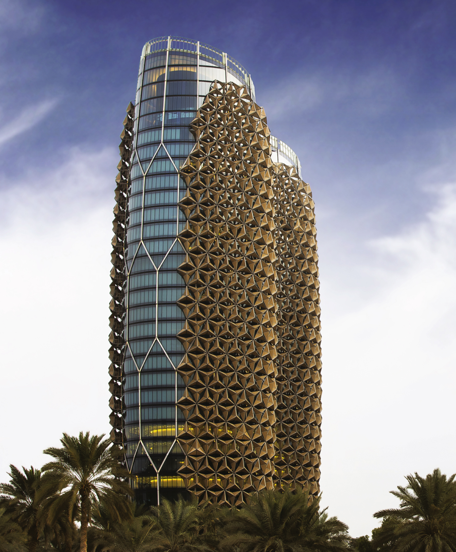
Fig.2
This map shows the location of the Al-Bahr Towers.
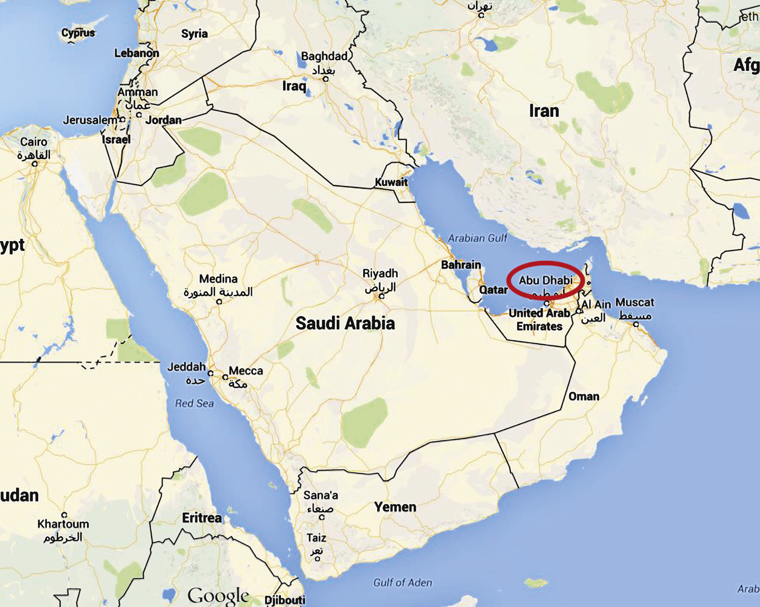
Fig.3
The Al-Jahili Fort demonstrates local building traditions.
Figs.4 and 5
Taj Mahal (left) and Al-Hambra Palace (right) are iconic examples of a universal geometric approach to design.
Figs.6 and 7
Circles and spheres form the base of Islamic geometric compositions. Examples of this are found in mashrabiya, such as those applied in Sheikh Lotfollah Mosque in Isfahan, Iran (left) and the Taj Mahal (right).
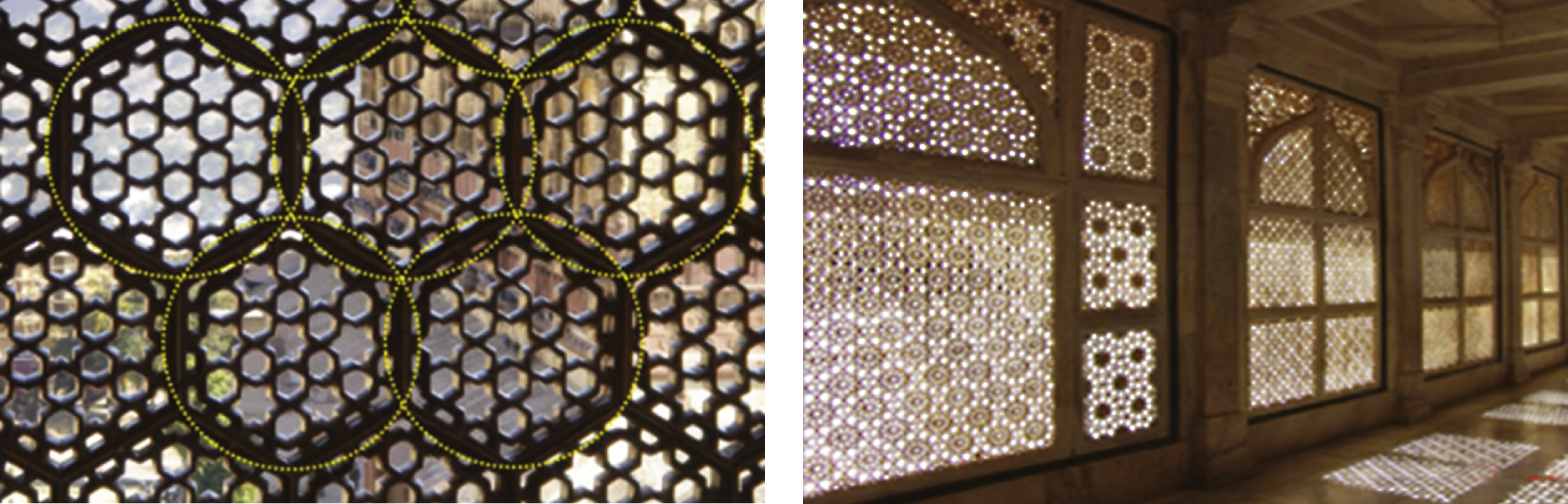
Fig.8
A custom designed computer application was used to simulate the operation of the Al-Bahr Towers automated screen as it responds to the movement of the sun (Mirenda, 2007).
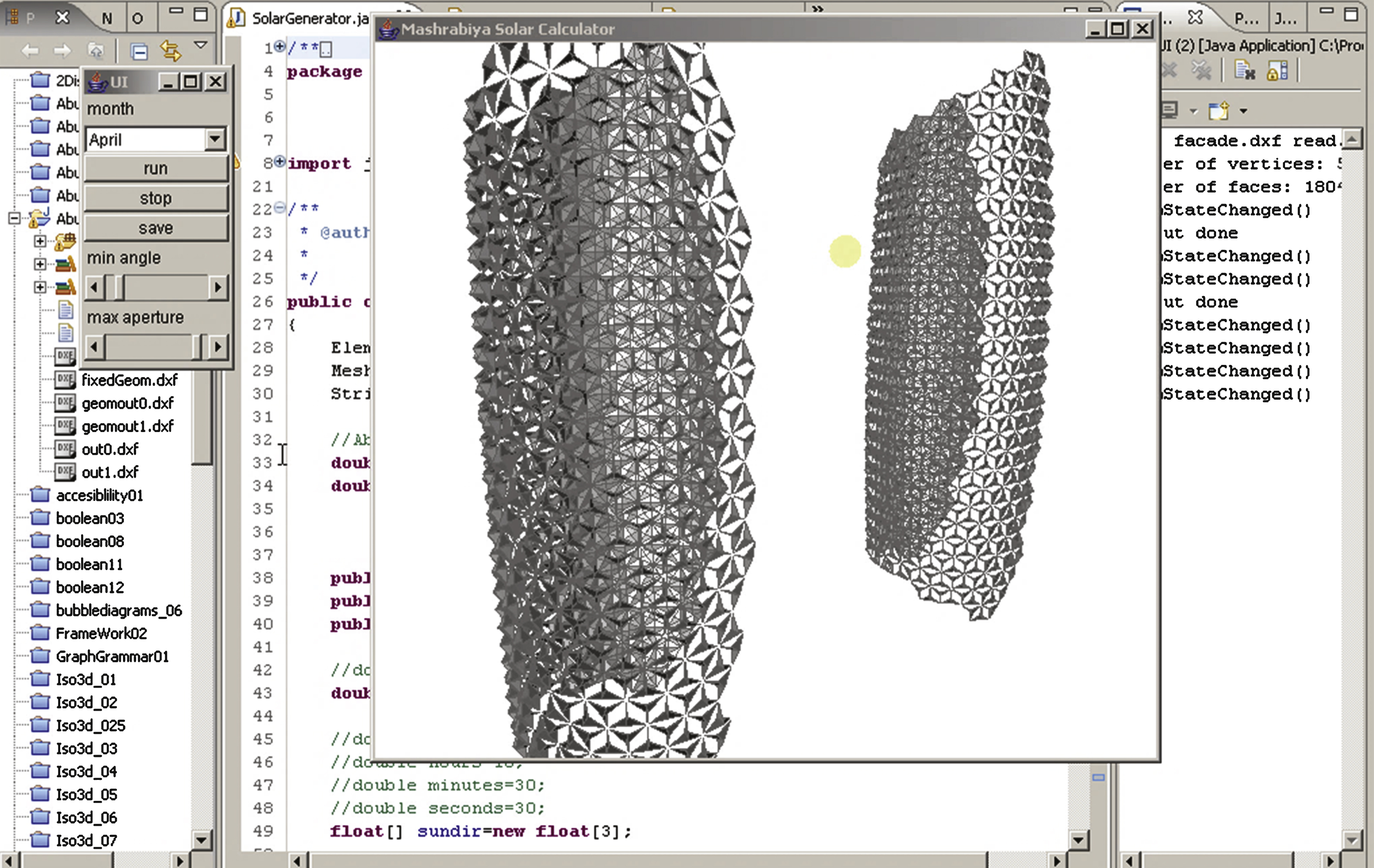
Fig.9
The Al-Bahr Towers competition stage concept diagram illustrates the driving principles of the design idea.
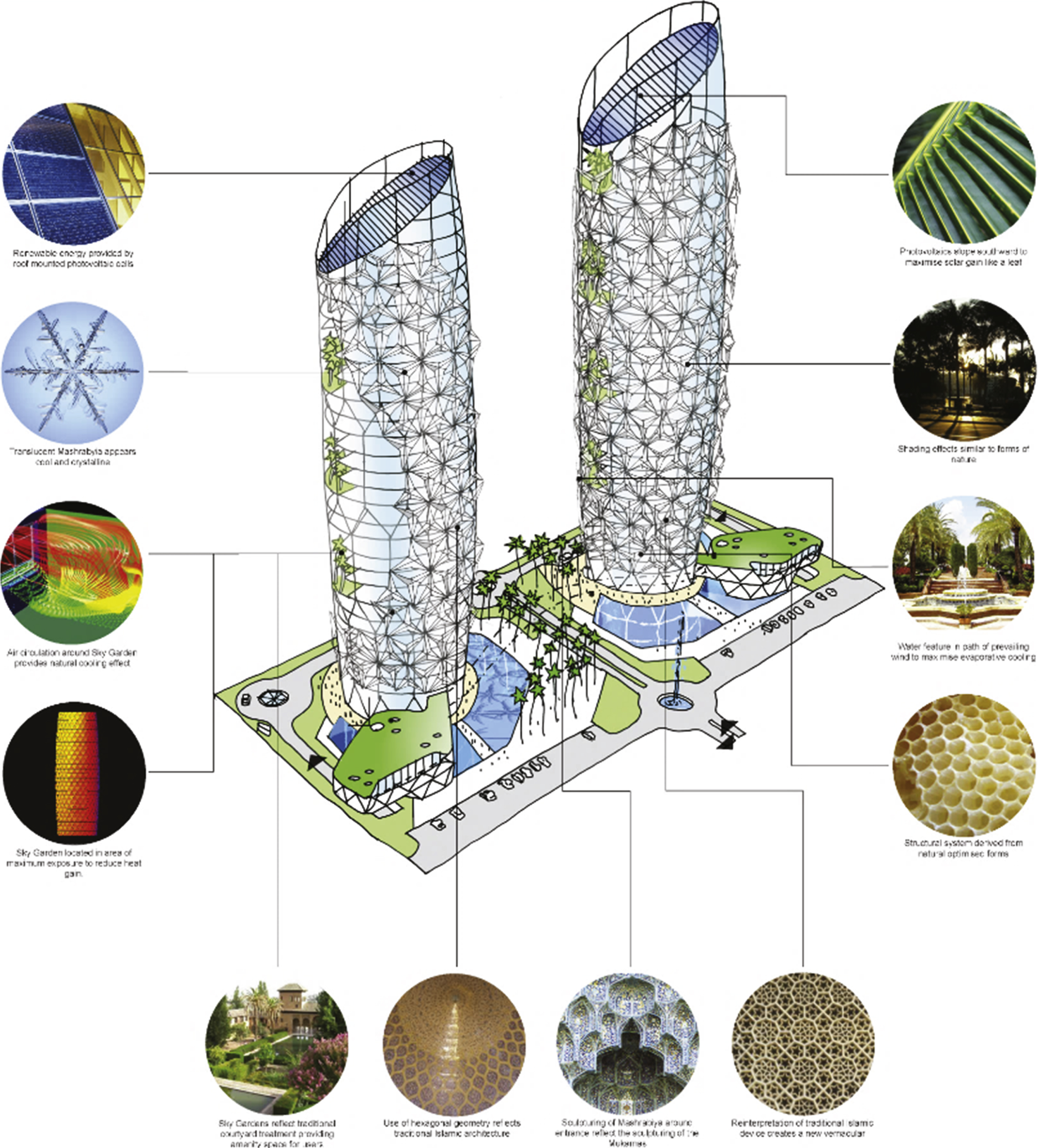
Fig.10
Dynamic mashrabiya – inspired from the past and from adaptive natural systems – folding and unfolding concept following the movement of the sun.
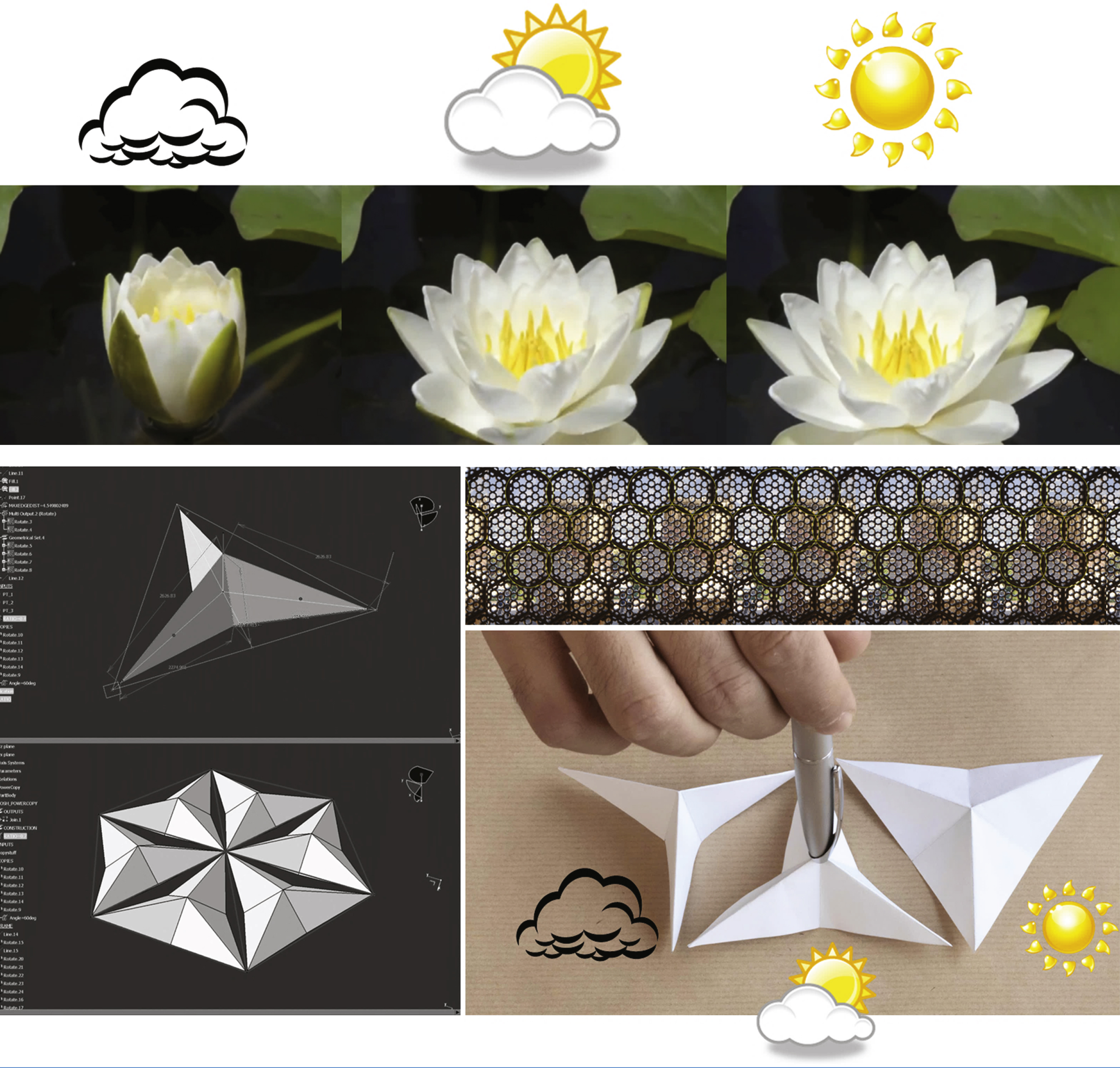
Fig.11
This comparison between common systems and the dynamic Mashrabiya system illustrates the different effects of the facade type in terms of visibility, admission of natural diffused light and overall internal working space quality.
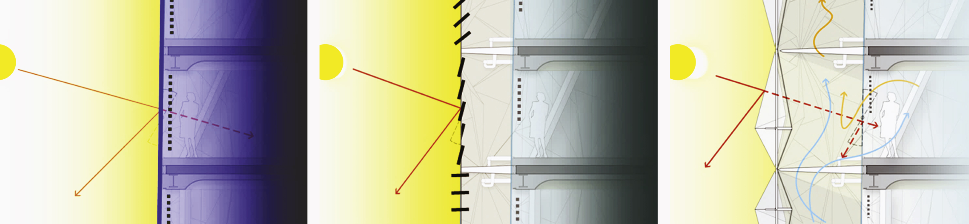
Fig.12
This schematic section through the south of the building shows the integration of the facade with key building elements like structures and mechanical services.
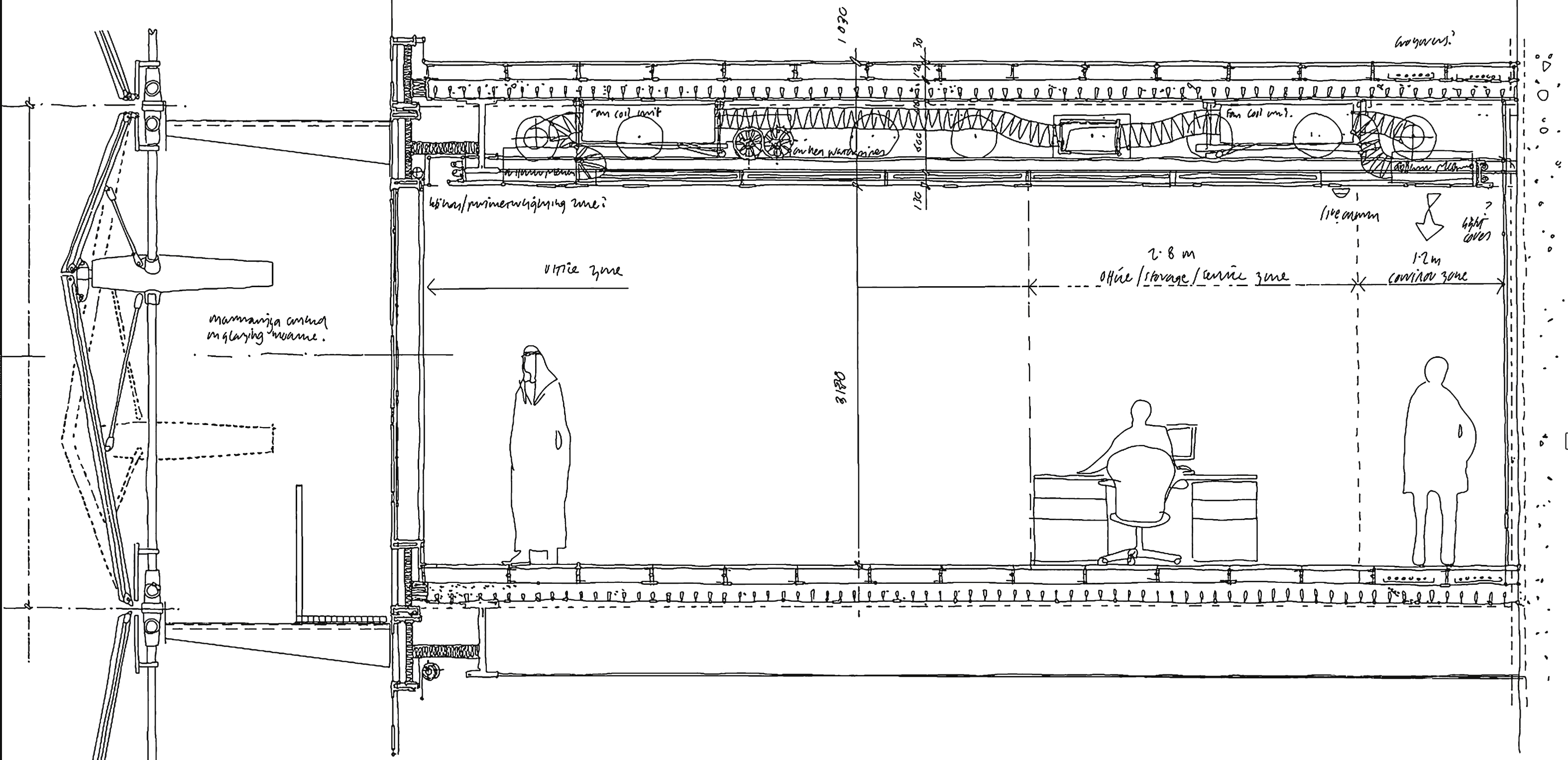
Fig.13
An assembled part of the building’s facade demonstrates the realisation of the CODE principles.
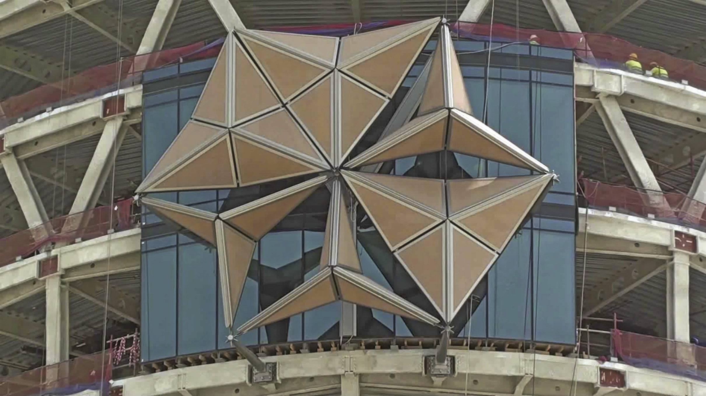
Fig.14
The total integration of systems was achieved by pre-rationalising the underlying buildings geometric principles.
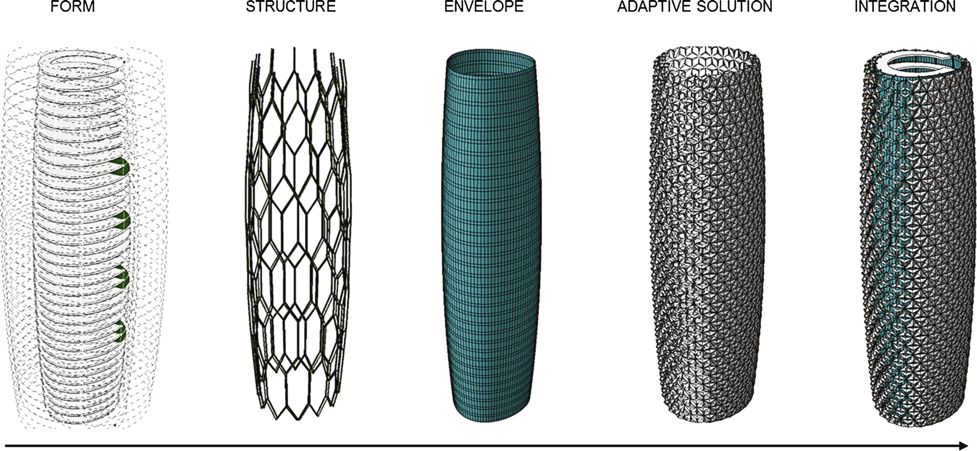
Fig.15
Shading studies were used to explore the impact on energy performance of different Mashrabiya configurations. This figure illustrates the facade opening and resulting improvement in energy performance during mid-season at 9:00 am.
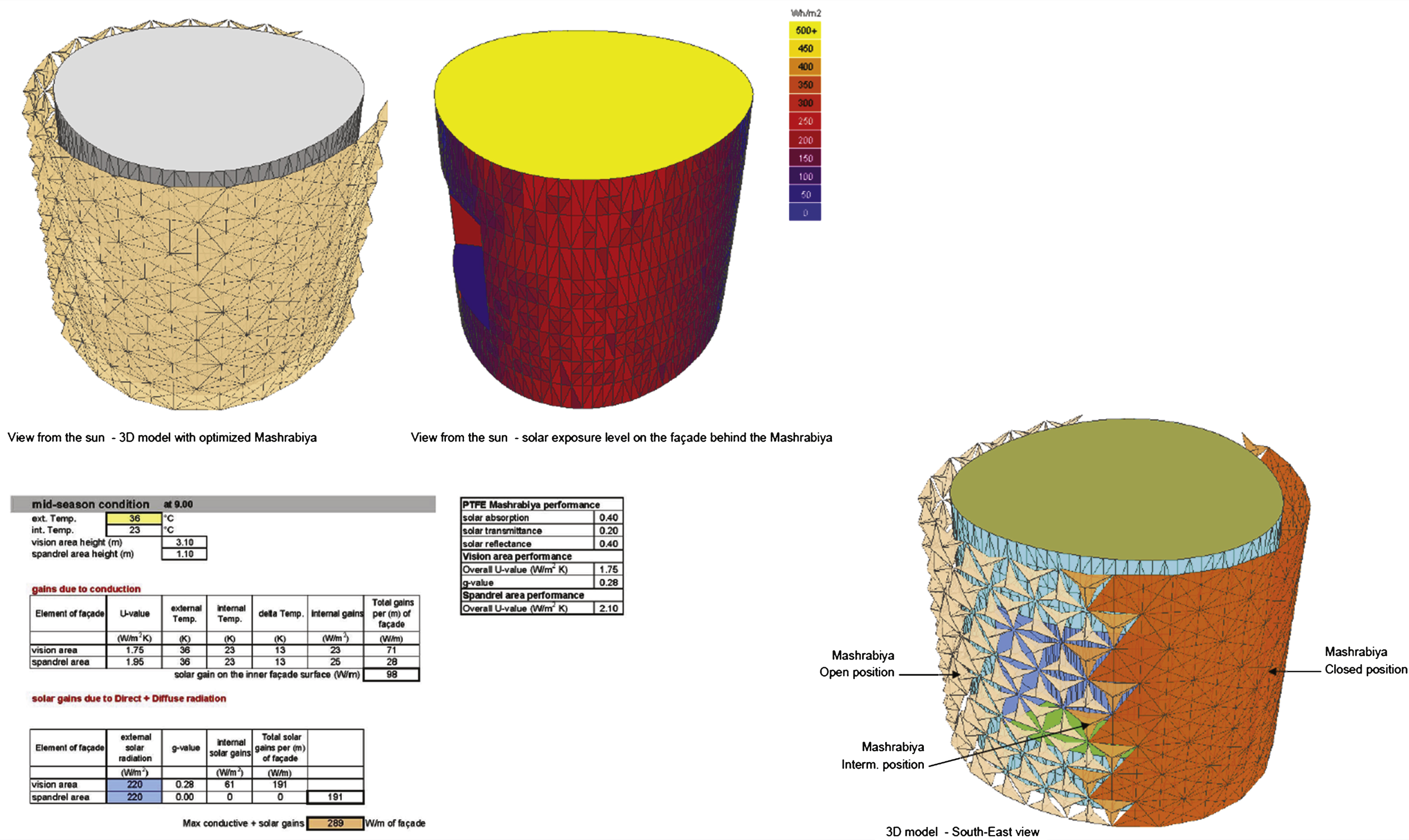
Fig.16
These figures illustrate the results of wind tunnel tests conducted on full-scale dynamic prototypes. The results reveal relatively low wind-loads due to the fluid geometry of the building and efficient form of the mashrabiya.

Fig.17
This image details the components of the dynamic facade.
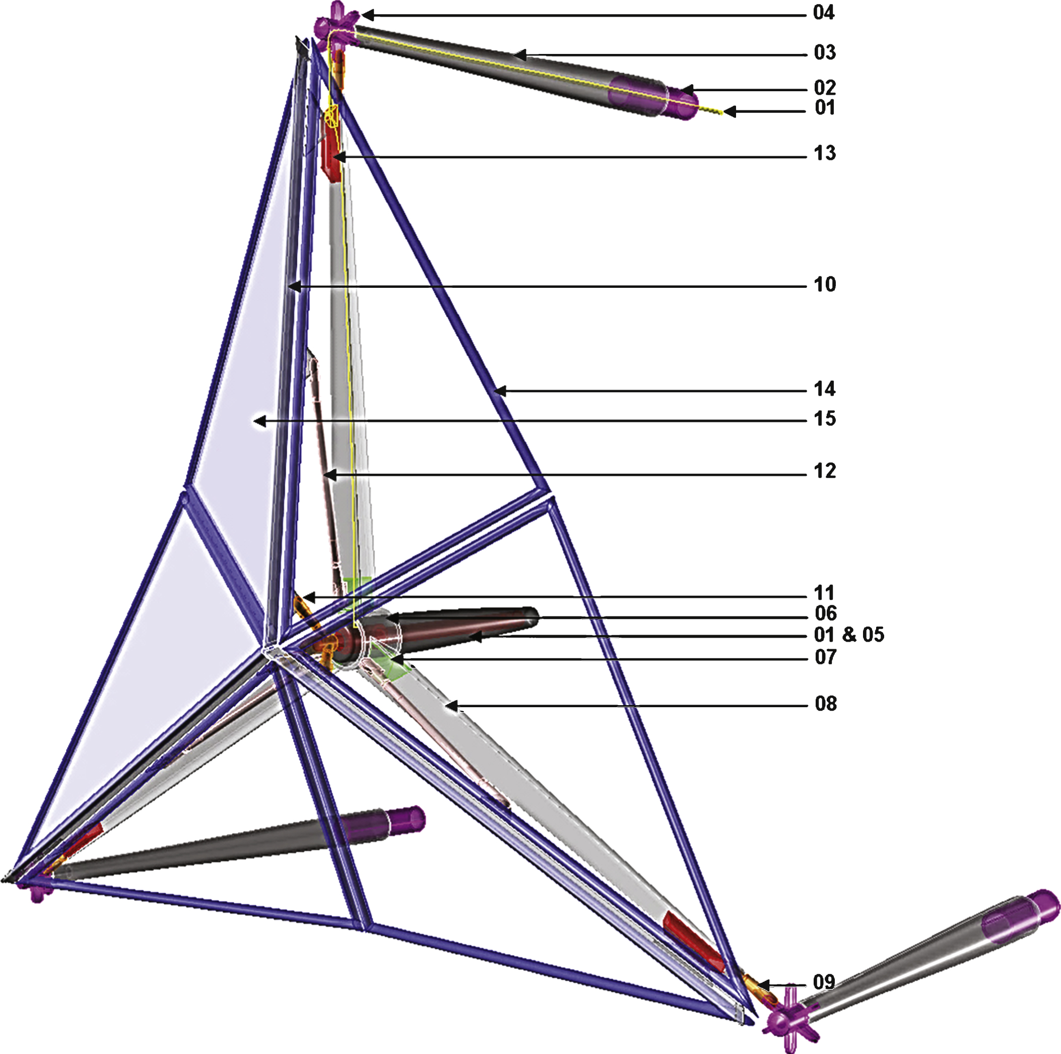
Fig.18
The software for the dynamic facade offers clear information and control.
Figs.19–21
These figures compare the cooling loads and carbon emissions between the mashrabiya and traditional envelope systems. Important Note: All figures and comparisons made in Figs. 19–21 take into account the entire building consumptions, including areas that are completely unaffected by the presence of the mashrabiya system like basements and parking areas, podium, vertical transportation, data centres, WCs, back of house, kitchens and so on. If however office working spaces are isolated from the rest of the building, the introduction of the mashrabiya screen can reduce energy consumption of those spaces in terms of lighting and cooling load requirements alone by up to 50%
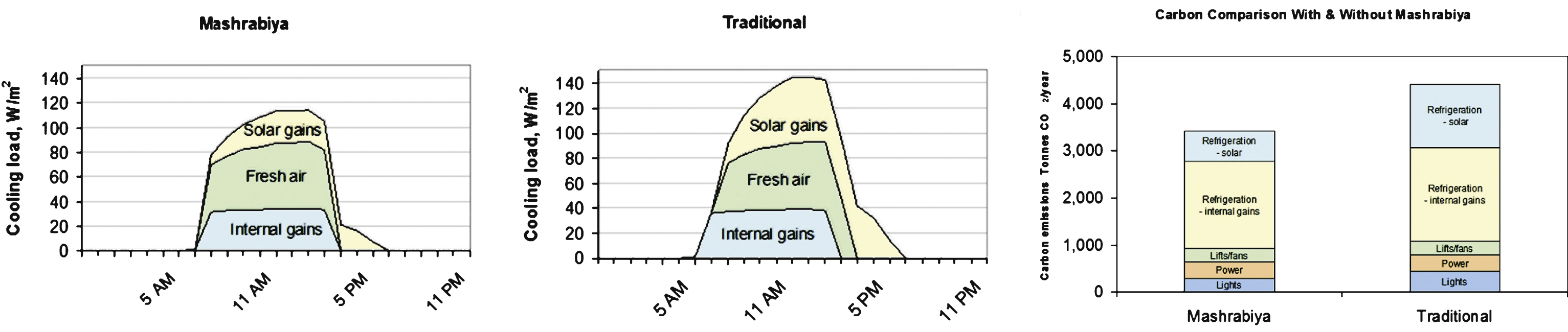
Fig.22
The diffused daylight reduced artificial lighting.
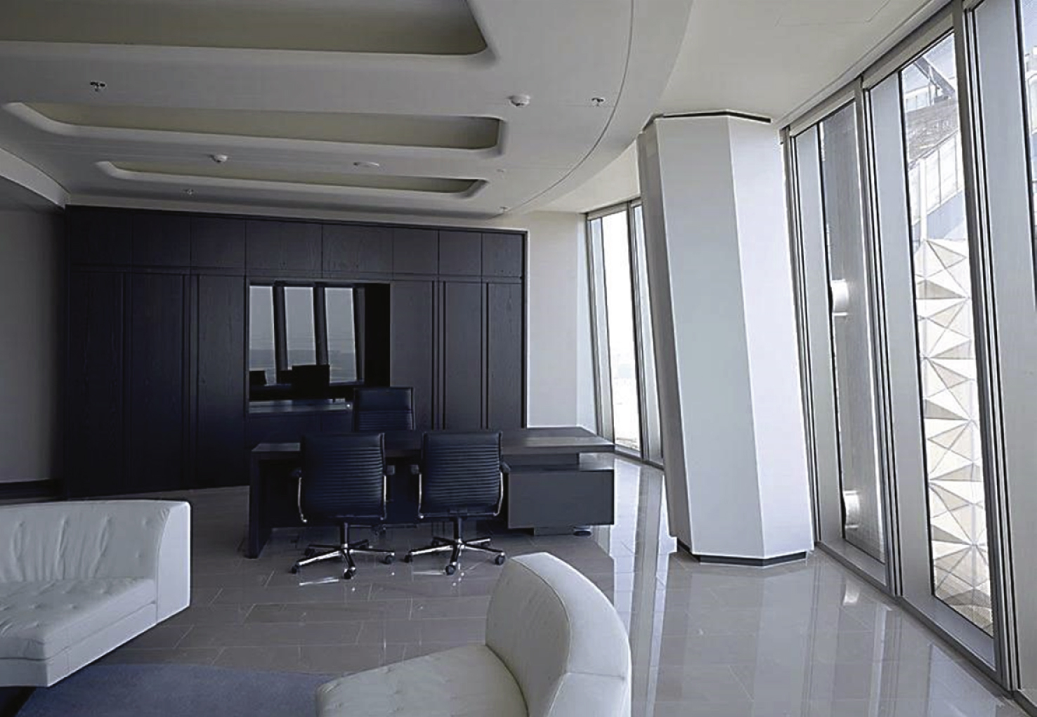
Fig.23
The fabric mesh and foldable system preserved views.
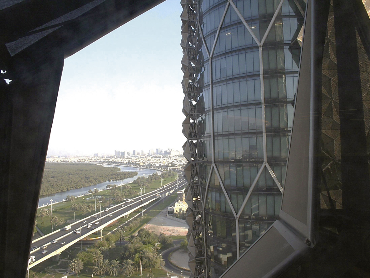
Fig.24
Sand, dust, and seawater was brought from Abu Dhabi and sprayed on full-scale components during life cycle tests. Inside a controlled testing chamber the dynamic unit was monitored over 30,000 cycles. This was the equivalent of eighty years of operation compressed into two months.
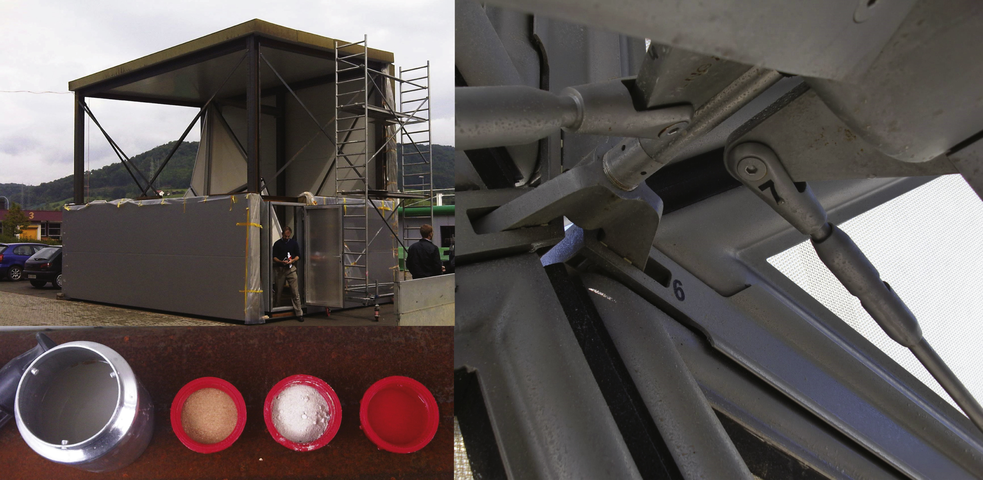
Fig.25
These images are part of a LEGO manual illustrating how to assemble a toy mechanism.

Fig.26
CODE steps ST 01 to 22, illustrate the communication of design principles used to develop the Mashrabiya geometry.
Fig.27
The Al-Bahr Towers form and floor plates were generated from arrangements of tangential circles dictated by an underlying radial grid. The building profile is generated by functions of zoning and area requirements.
Fig.28
The Al-Bahr Towers curtain-wall and honeycomb structure were defined by the linking of nodes generated from the intersection of tangential circles and the extrusion of the underlying radial grid.
Fig.29
This diagram shows the 800 mm-curtain-wall/floor-plate perimeter buffer zone where direct solar rays are allowed to land inside the building. Such condition only occurs during limited hours of the day during the summer where solar rays land on the curtain-wall surface at an angle higher than 83 degrees. Solar rays that travel deeper than the identified buffer-zone will be blocked by the dynamic mashrabiya solar screen system by deploying mashrabiya units in a suitable optimized opening configuration.
Fig.30
ST 29: Time: 13:30, 79 < Sun-Angle <83°.
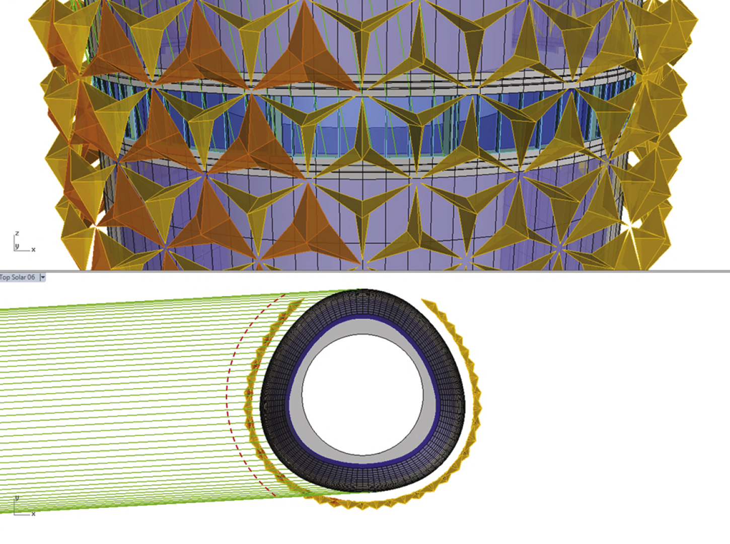
Fig.31
ST 27: Time: 09:07, 79 < Sun-Angle <83°.
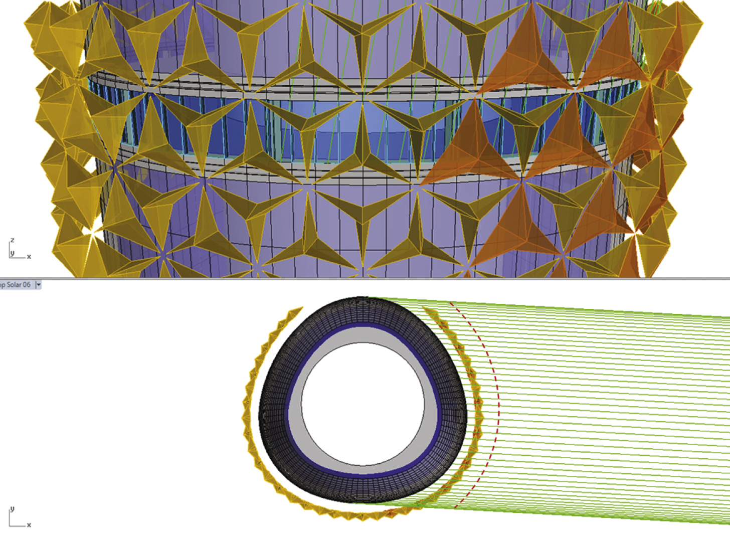
Fig.32
This view shows the Al-Bahr Towers as seen from Salam Street.
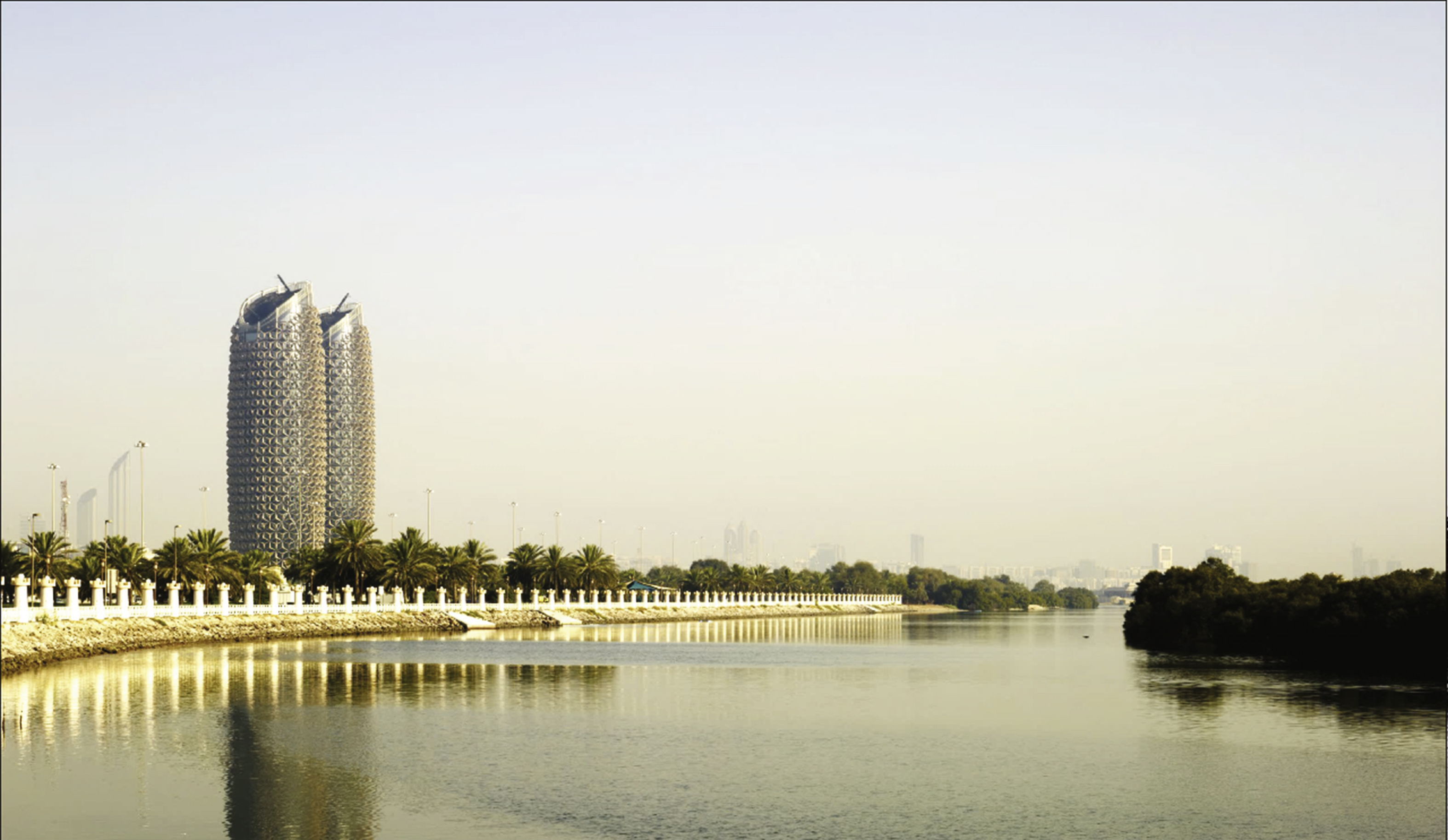
Fig.33
The Mashrabiya of the Al-Bahr Towers as seen from the outside.
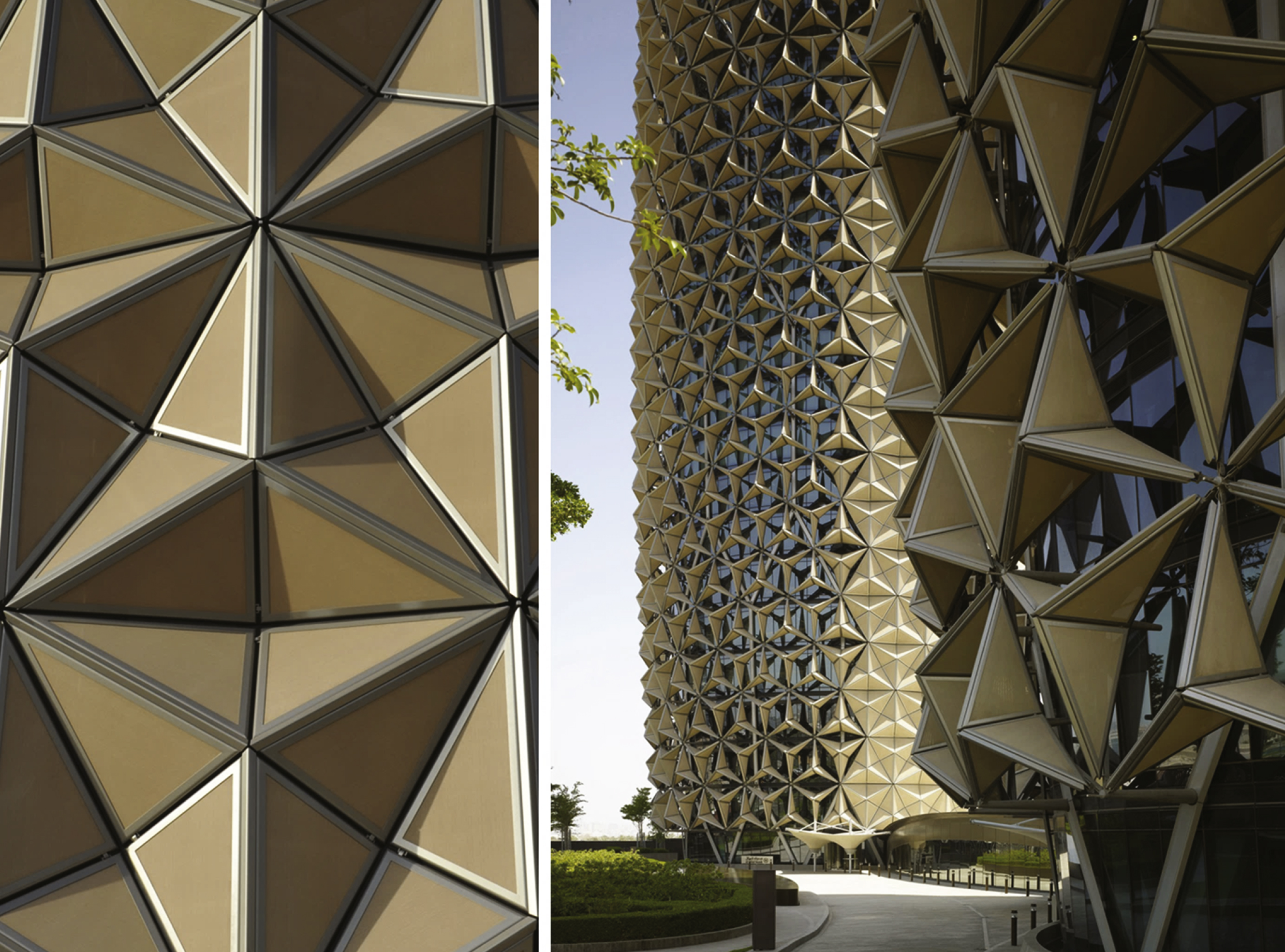
Fig.34
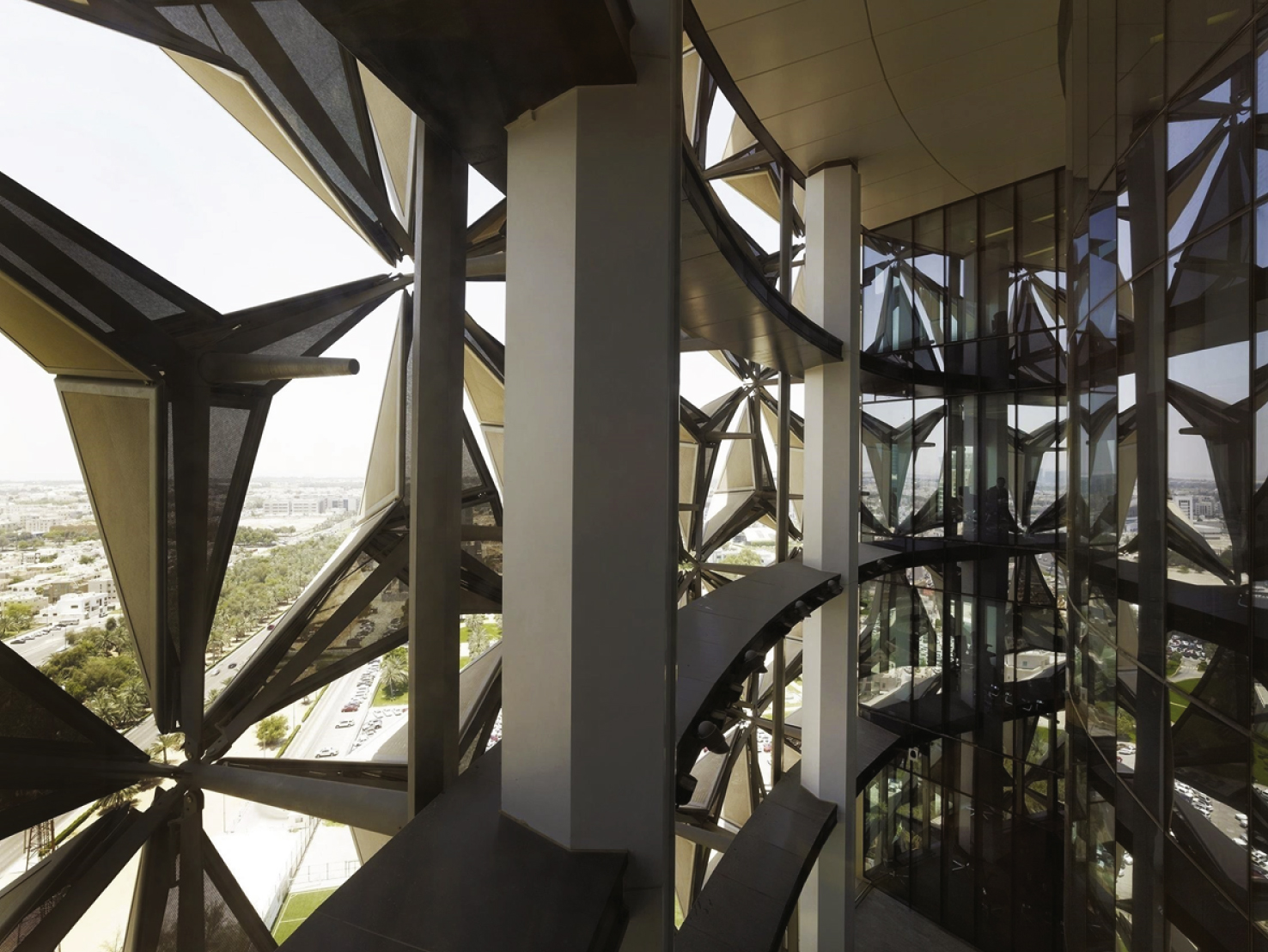
The Mashrabiya of the Al-Bahr Towers as seen from the inside – Sky garden open space.