
Potential for innovative massive building envelope systems – Scenario development towards integrated active systems
Abstract
In order to generate possible scenarios about future developments of massive constructions, this paper explains the developmental paths on the basis of individual materials of clay/brick as well as concrete/lightweight concrete/aerated concrete and sand-lime brick. These construction types are organised qua development level on a roadmap, structured by a timeline and the division in massive and skeleton construction. By this development, lines of constructions appear, structured by the order of additional functionalities integrated in each development step. Following this path, possible scenarios for future developments of integrated active systems are sketched, following the line of additional functionalities being integrated in the construction. Drawbacks such as the limitation of recycling of integrated constructions and the conflict of insulation versus load bearing capacities are named. As a result two strategies are expressed: the light massive envelope construction with integral layers and the massive oriented solution with possible exchangeable components are developed and illustrated by five general construction principles.
1Outline, research question and goal of the paper
This paper investigates the functionality of massive building envelope constructions, their functional and technical performance development level. Based upon this, it is expected to be able to understand the order of the development of the construction, expecting an increase in performance with each evolutionary step. As a consequence the research question ‘how to structure the developments of the massive building envelope?’ evolves. A roadmap is developed as an instrument to express and structure this development.
Following the evolution process the second research question ‘Which future requirement will be targeted and by which developments of the massive building envelope will they be solved?’ is the consequence. Possible scenarios will be sketched.
2Functionalities and roadmap of the massive building envelope
In order to identify possible future scenarios we have to understand the developmental paths that led to our current state of knowledge and identify issues and potentials that future questions and requirements might bring. The input parameter for any such discussion is (are) the required function(s) a wall needs to fulfil.
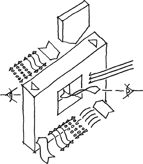
Sketch 1
Constructive functions of a wall: construction (own weight, thermal expansion, horizontal stress), climate control (temperature, humidity, acoustic, light and view).
The functionalities of a massive building envelope can be defined by the following topics (Klein, 2013)
– construction loads (own weight, thermal expansion, horizontal stress),
– construction method (process, production, construction),
– climate control (temperature, humidity, storage capacity, acoustic, light and view),
– sustainability (embedded energy, usage energy, recycling),
– usability (safety, fitness for use, maintenance),
– appearance (urban context, exterior and interior perception).
With the defined functionalities it is possible to evaluate the performances of a building envelope – with the possibility to rank the constructions in terms of development level and, in parallel, to identify missing aspects. To express the developments, sketches of the construction types are assembled in a roadmap. To organise the construction types on the roadmap, this evaluation is done by identifying the functionalities of each construction in terms of performance and order of development. The roadmap is organised via a timeline, starting with the early construction technologies on a horizontal line. In the vertical direction it is organised via the simple parameters massive/skeleton construction – to allow separating the systematic without becoming too complex in the investigation, which would conflict with the need of a fast and simple access of the roadmap. To visualise the construction for a better understanding, the various building envelope technologies are documented as 3-D sketches, focusing on the principle key aspects of the construction (Knaack, 2011).
The general roadmap shows the building envelope construction in terms of development order. This delivers the possibility to position the different construction types of building envelopes within a historical and functional development, following a developmental path of the technical solutions, in which individual solutions can be positioned to document the logic of the development. In most – but not all! – cases the individual technologies that are part of such a developmental path follow a chronology – and thus they document the development of the function integration of the construction types.
By using the historical and functional development and the positioning on the roadmap, potential directions of development can be identified – even if the technology to serve a particular functionality is not yet available. In a second step technologies to serve the requested performance can be investigated, and if identified they can become subject areas of yet to be integrated solutions.
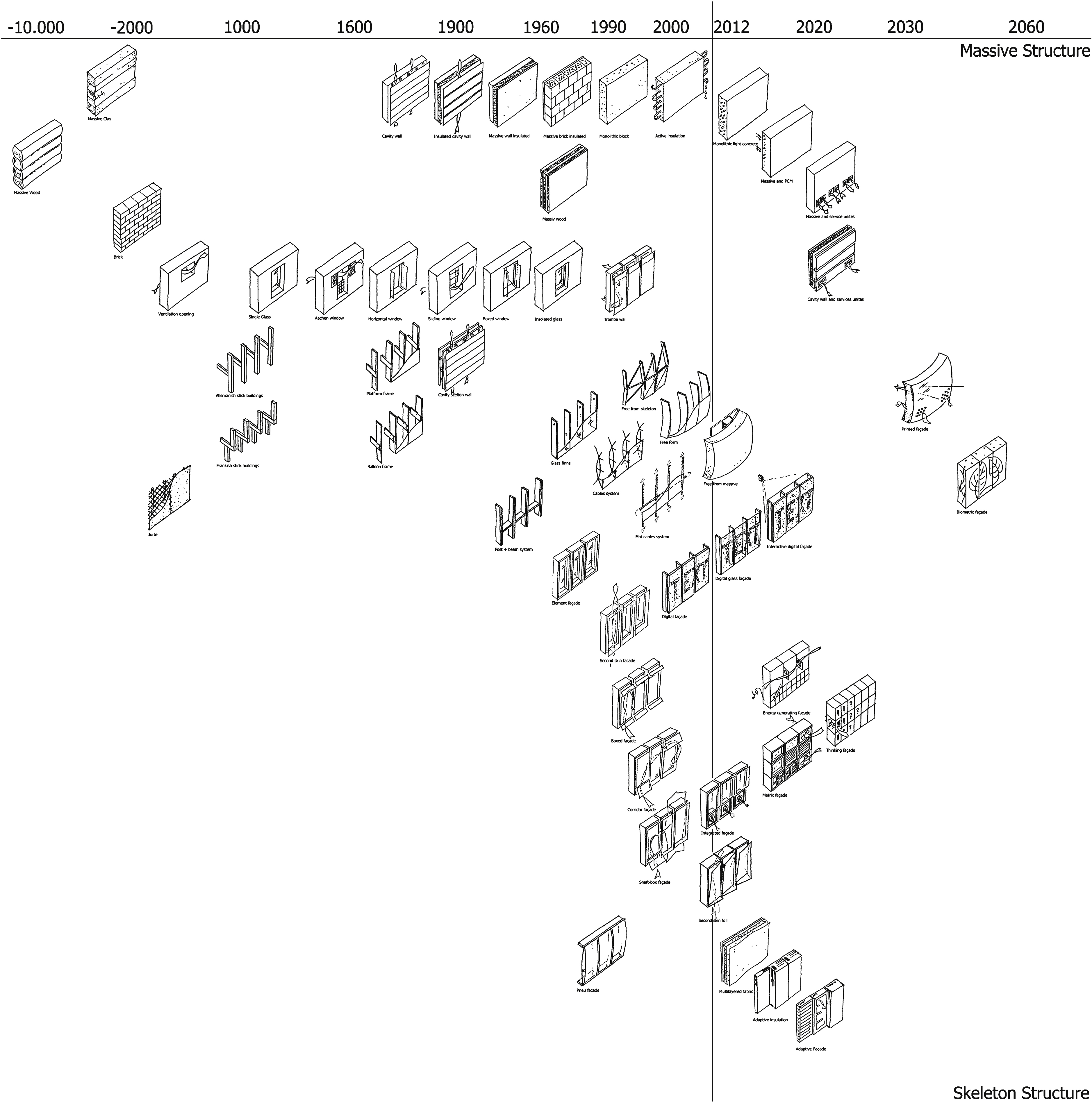
Sketch 2
Sample of a general roadmap of building envelope construction organised by a horizontal timeline and vertically via the parameters massive/skeleton construction, status 2011 (Knaack, 2011).
3Stacking materials
When considering the primal urge to protect ourselves – i.e. creating a shelter – one solution besides creating a lightweight envelope – the tent – is to stack materials. The most basic form is to stack readily available materials such as broken stone (natural stone masonry) and trees (wood block construction).
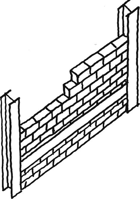
In order to minimise material use, the technology of timber frame construction was developed for wooden constructions. Hereby, massive timbers were positioned such that bays were formed which needed to be filled in with wattle and clay. Later, these bays were filled in with bricks – a technology that will be discussed further on in this paper. The logical developmental consequence was to replace the timber with steel: steel frame construction with infills made of brick.
As a side note it needs to be mentioned that timber frame construction was followed by stacked board construction, which today can be found in a modified form as planar stacked massive construction made of veneered laminated wood (Pfeifer et al., 2001;Marti et al., 2005).
Sketch 3
Natural stone masonry.

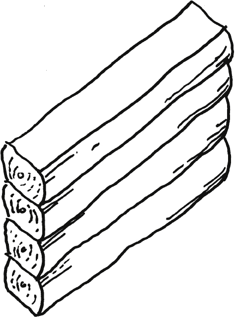
Sketch 4
Block construction.
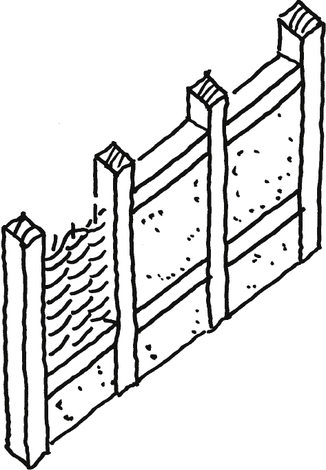
Sketch 5
Timber frame construction with clay infills.
Sketch 6
Timber frame construction with brick infills.

Sketch 7
Steel frame construction with brick infills.
Sketch 8
Stacked board construction.
Sketch 9
Veneered laminated wood construction.
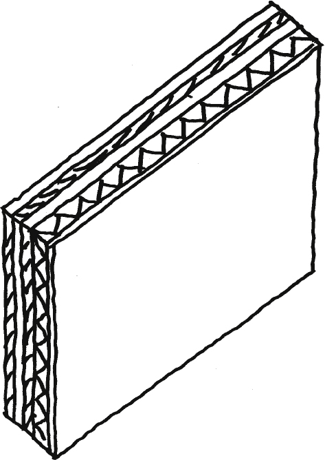
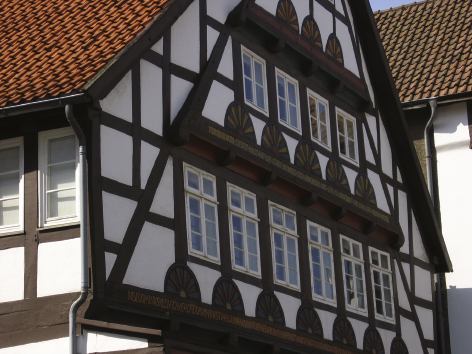
Fig. 1
Timber frame construction with clay infills.
4Clay, adobe, and brick
In the field of massive constructions, clay was eventually used as a replacement for broken stone. In order to make the material usable for wall construction it was either ‘stacked’ by setting up provisional formwork which was then filled with clay, or by forming clay into prefabricated bricks which were dried by the sun; a method which was most likely first developed in Egypt around 12.000 B.C. To reinforce the clay, additives and fibres such as animal hair and straw was added (Pfeifer et al., 2001; Encyclopaedia Britannica, 2013).
Around 2500 B.C. the technique of burning the clay was developed in the Nile and Indus regions as well as in Mesopotamia. The burning process changed the material state (silication) to improve the material’s durability, particularly in terms of water resistance. In the following, the technology was mainly distributed by the Roman Empire. To further safeguard the masonry, constructive elements such as natural stone plinths and projecting roofs were implemented as well as protective layers – at first lime washes and later exterior and interior plaster which had the additional benefit of serving as decoration (Marti et al., 2005; Deplace et al., 2005).
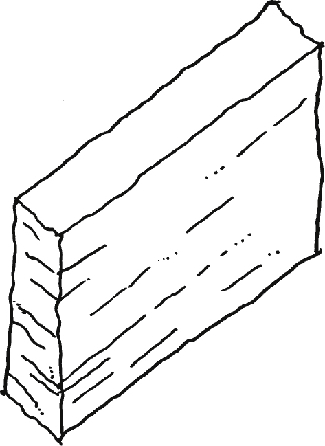
Sketch 10
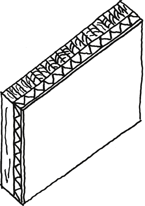
Stamped clay wall.
Sketch 11
Clay brick.

Sketch 12
Burned clay brick.
Sketch 13
Masonry with plaster.
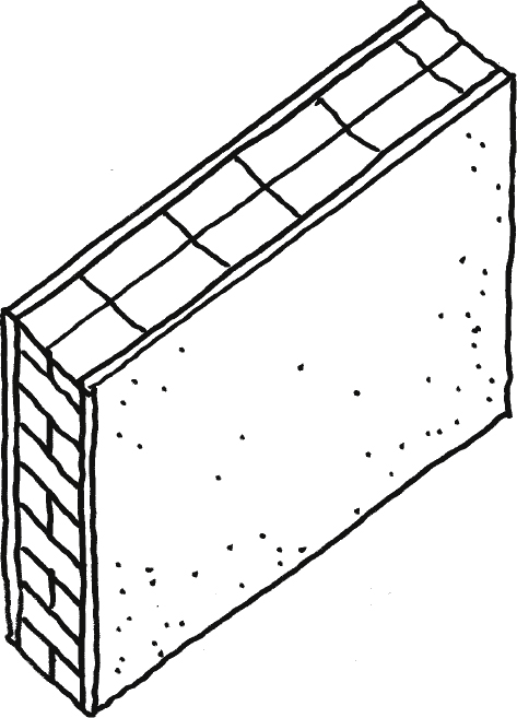
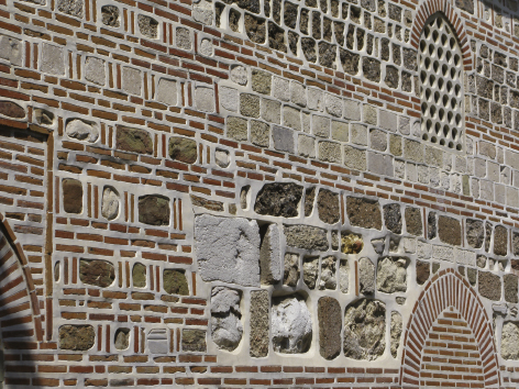
Fig. 2
Mixed natural stone and burned clay brick masonry.
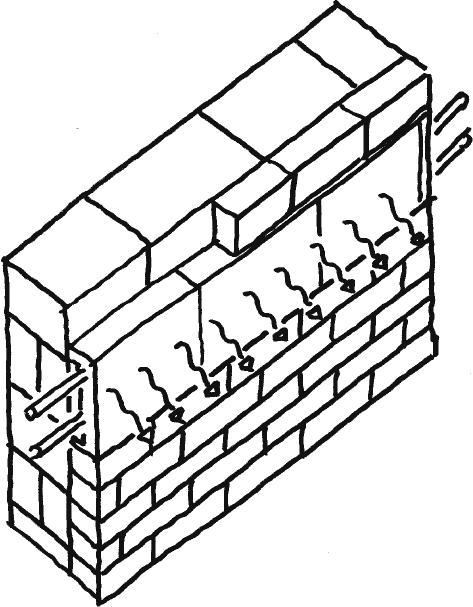
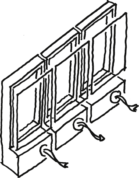
Along with the technological developments, additional functional requirements arose that the wall needed to fulfil. Its main purpose was no longer solely to envelope, i.e. the construction (own weight, thermal expansion, horizontal stress), but to control the climate as well (temperature, humidity, acoustic, light and view). These new requirements led to layered wall constructions that on one hand increased the load-bearing capacity (multi-layered masonry and masonry-concrete composite constructions), and on the other optimised the insulating capability of the wall, e.g. the rear-ventilated wall. The thought behind this concept is that the vertical air layer creates an additional thermal buffer, which can also serve dehumidification if accordingly ventilation slots are added. Following the logic of insulation, additional insulating layers are added in a next step within the rear-ventilated gap (Pfeifer et al., 2001; Marti et al., 2005).
On the sideline of this development are activating systems, a development from the last decade. Here, heating systems are integrated into the wall to increase its thermal performance; either as planar elements or as integrated heating panels.
As alternatives to exterior envelopes made from masonry, other planar cladding materials are applied such as wood, sheet metal, mineral panels or plastics. And there are solutions that reverse the material sequence of a wall construction, e.g. an exterior layer of masonry that is attached to a load-bearing wooden construction. Thus, the masonry is an enveloping element that is no longer used for load-bearing purposes. A closer look at these developmental paths highlights that this solution runs analogue to timber frame construction.
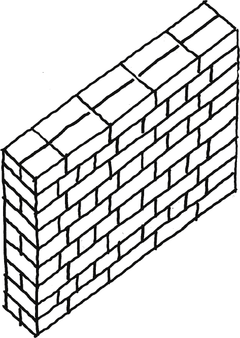
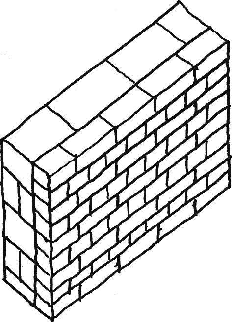
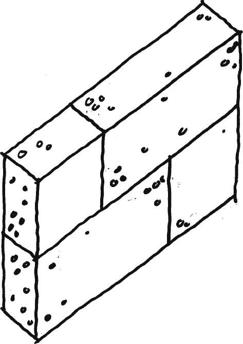
Sketch 14
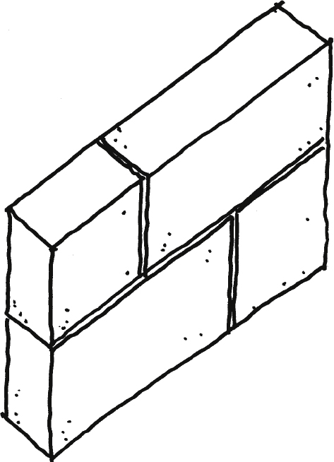
Stacked masonry.
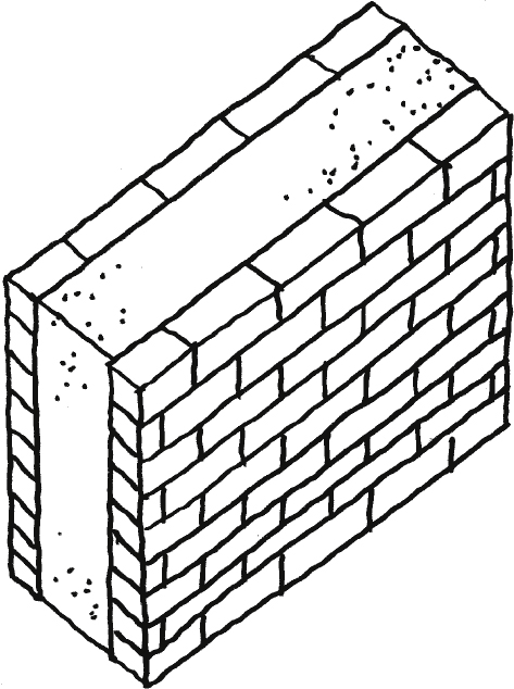
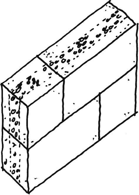
Sketch 15
Masonry-concrete composite constructions.
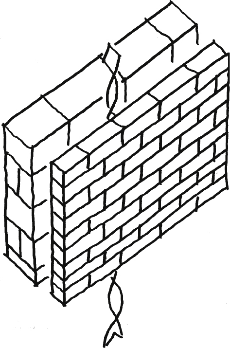
Sketch 16
Ventilated masonry wall.
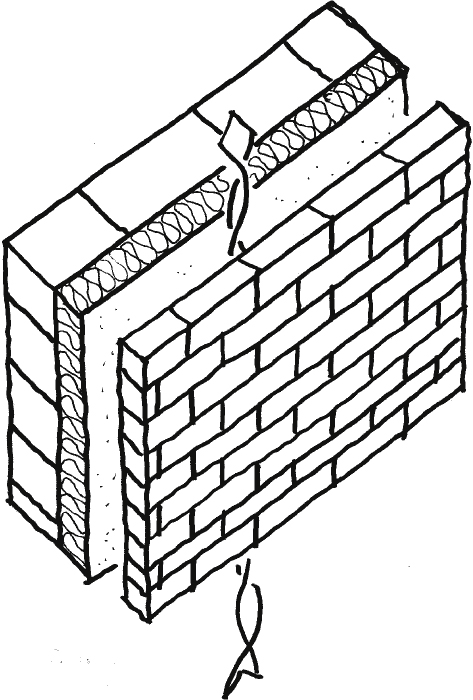
Sketch 17
Insulated ventilated masonry wall.
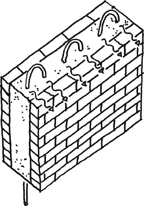
Sketch 18
Heating system in form of planar elements in the wall.
Sketch 19
Heating system in form of an integrated heating panel.
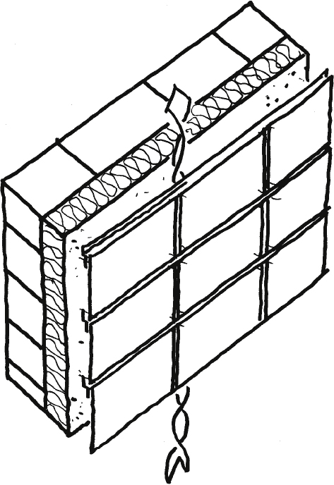
Sketch 20
Insulated rear-ventilated masonry wall with cladding
Sketch 21
Wood skeleton with masonry cladding.

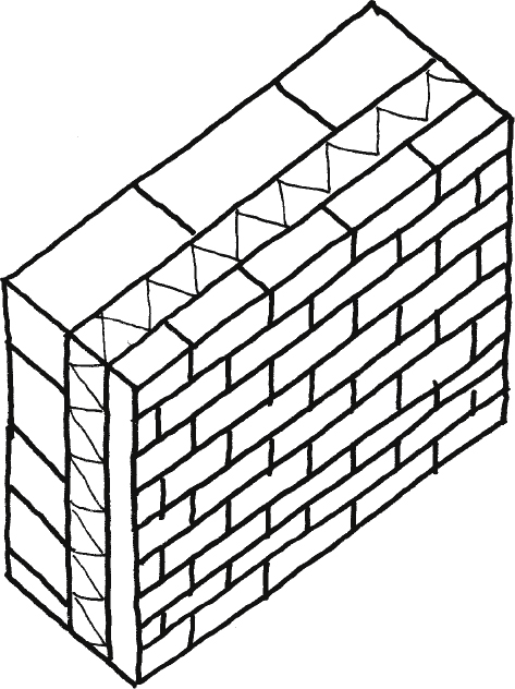
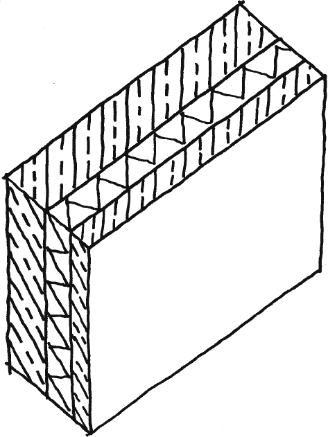
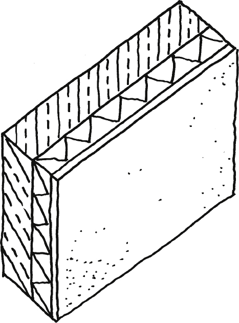
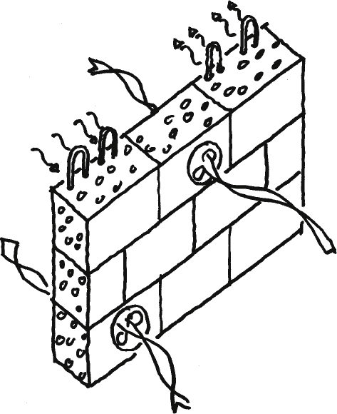
Closed systems were developed as an alternative to the rear-ventilated systems. With these systems, the insulating layer is positioned either between two layers of masonry – masonry with core insulation – or on the exterior side of the masonry – thermal insulation composite systems. For the latter, the exterior was enclosed by a thin layer of plaster. Here, particular attention must be paid to the water repellent exterior layer because the system cannot be dehumidified.
The developmental step toward lightweight brick is a logic consequence of the concept of compact yet insulating masonry. The results are vertically perforated bricks made with an extrusion process that are usually covered with plaster to protect against humidity.
Sketch 22
Masonry with core insulation.
Sketch 23
Masonry with thermal insulation composite system.
Sketch 24
Vertically perforated brick.
5Concrete, lightweight concrete, limestone
The ‘Opus Caementitum’ of the Roman era is usually considered the first concrete; however, much earlier evidence of lime mortar constructions was found in Turkey/Syria, Palestine, and Egypt. Those constructions consisted of a mixture of lime mortar and broken stone as additives. Interestingly enough this technology was mostly lost during the Middle Ages, to become revitalised as late as in the 18th century in the form of stamped concrete, analogue to the stamped clay of earliertimes.
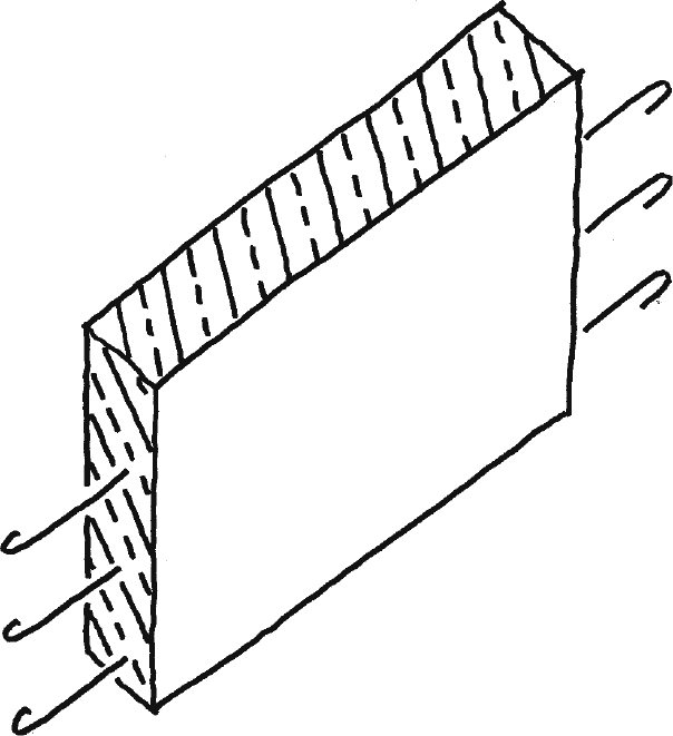
With the goal to strengthen the concrete in terms of tensile-loaded capacity, reinforced concrete was developed during the 19th century simultaneously in England (Willam Boutland Wilkinson) and France (Josef Louis Lambotas and Joseph Monier). Reinforced concrete is a composite of concrete and iron tension rods, which also improves the functionality of the material as it allows for slimmer constructions (Kind-Barkauskas et al., 1995).
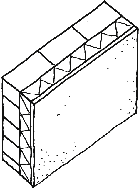
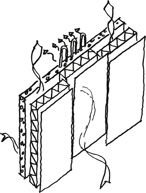
Similar to the development of brick building, climate control in the sense of improved insulating properties gained importance in a following step. This resulted in sandwich constructions in the form of concrete-insulation-concrete constructions or thermal insulation composite constructions (Stacey, 2011).
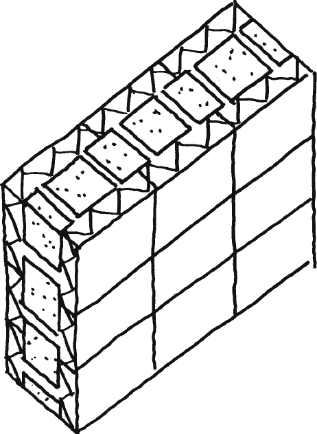
So-called Styrofoam bricks can be considered a subgroup of this development. Hereby, hollow polystyrene shaped bricks are stacked, and filled with concrete once the wall is erected. This technology was mainly developed following the concept of simple building processes.
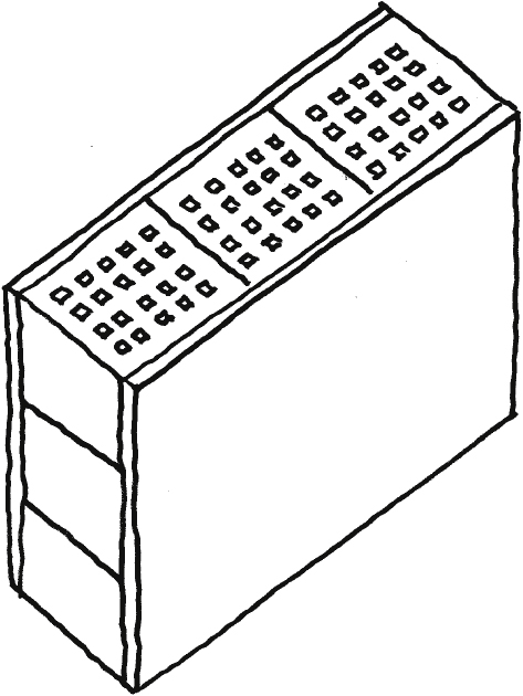
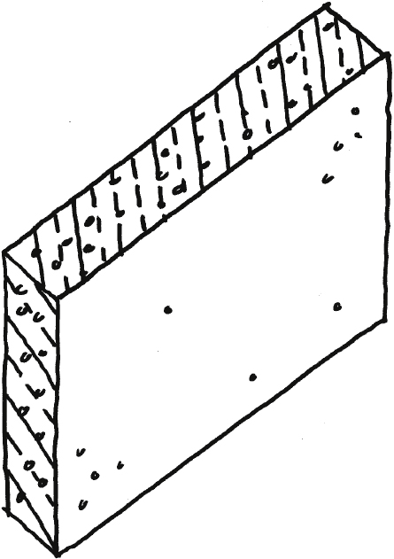
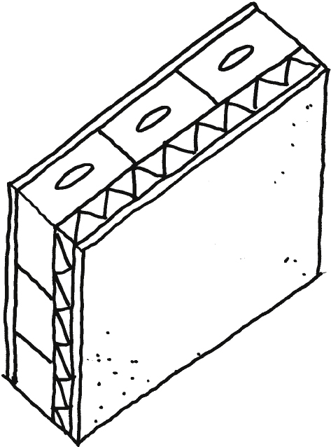
Over the past decades, the use of additives has allowed to produce lightweight concrete (e.g. gas concrete). If used in the form of massive wall constructions they comply with the current conception of insulating building parts. However, the disadvantageous effect on the load-bearing capacity of the construction led to further developments, which involved adding additives that were distributed in a targeted manner. Building components made of such gradient concrete help to dissipate stress forces in the system and, at the same time, to increase the insulating capacity.
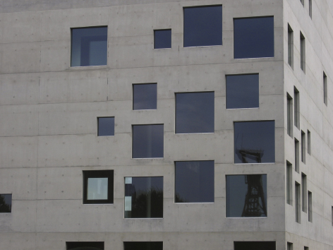
An alternative strategy is active insulation, developed by M. Schuler in 2006; it was used in the project Design school Essen by SANAA. Here, heating pipes are inserted into the concrete to warm the construction and avoid cooling off. This concept, of course, requires the necessary energy resources (Knaack et al., 2007).
Sketch 25
Opus Caementitum.
Sketch 26
Reinforced concrete.
Sketch 27
Sandwich construction.
Sketch 28
Concrete with thermal.
Sketch 29
Styrofoam stones with concrete.
Sketch 30
Lightweight concrete.
Sketch 31
Gradient concrete insulation compound system.

Sketch 32
Concrete with active insulation.
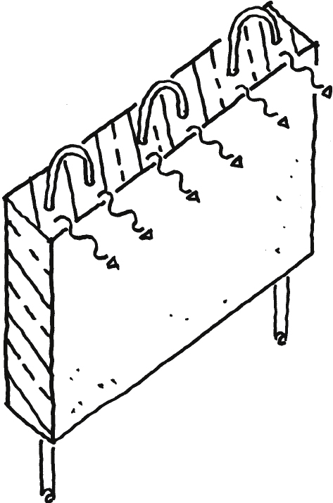
Fig 3
Design School Essen, a concrete construction with integrated active insulation.
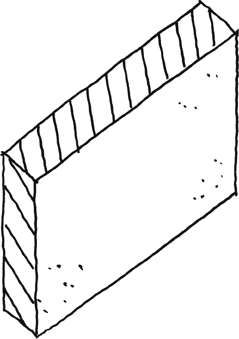
Also composed of lime and sand, the lime sand brick was developed around 1860, and patented by W. Michaelis in 1880. It consists of earth-moist sand that is mixed with lime, and then cured under hot steam and pressure. The results are dimensioned stones that can also be applied in large formats. In structural application it is used for massive walls, clad walls, walls insulated with a thermal skin and in the shape of vertically coring lime sand bricks (Pfeifer et al., 2001).
With the goal to make constructions lighter and increase their insulation values, the first aerated concrete was patented by E. Hoffmann in 1889. It consisted of hydrochloric acid and lime stone powder. The curing process produces gaseous hydrogen that lets the mortar rise and creates pores. A second step in the development was a solution patented by J.W. Aylsworth in 1914. It involved mixing metal powder (aluminium/zinc), quartz sand, lime, and water and then curing the mixture. The resulting bricks are produced in various formats, up to large format prefabricatedparts.
To further increase insulation capacity, sandwich solutions within the field of aerated concrete were developed that featured a lighter inner layer – thus with higher insulation values – while the function of load-bearing was allocated to the outer layers (Kind-Barkauskas et al., 1995; BV-Porenbeton, 2013).
Sketch 33
Lime sand brick.
Sketch 34
Vertically perforated lime sand brick with plaster.

Sketch 35
Lime sand brick with thermal insulation composite system.
Sketch 36
Aerated concrete.
Sketch 37
Sandwich construction aerated concrete.
6Limitation of the approach
It has to be noted that the topic of appearance and structural development of the massive construction is not subject of this paper, since its purpose is to derive technical developments of the construction itself. This leads to the fact that this paper mainly focuses on one detail of the overall topic of massive constructions. Areas such as structural joints and apertures in the walls, as well as the direct consequence of a structural dissolution of the construction in the course of the gothic period, with the resulting skeletal constructions, can only be mentioned to a limited extent: following the basic structural experiences, arched constructions were developed to allow massive constructions to span spaces. The gothic period continued this development: increasing dimensions while at the same time reducing the amount of used material – with the consequence of concentrating the forces towards more column-formed structures. One notable example is Antonio Gaudi who followed this strategy with the project Sagrada Família, started in 1882, and developed with his hanging model the consequent force oriented structure – allowing minimal material mass being used in a compression loaded masonry structure (Pfeifer et al., 2001).
Fig. 4
Roman aqueduct close to Avignon/France.
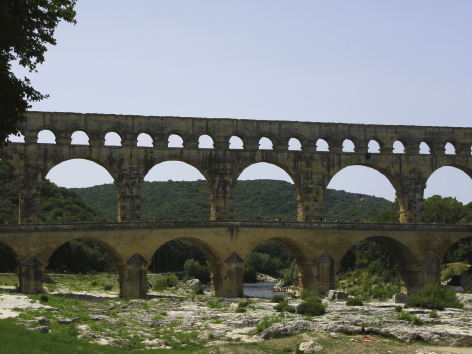
Fig. 5
Gothic cathedral of Noyon/France.
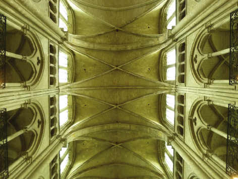
Fig. 6
Sagrada Família Barcelona/Spain.

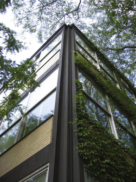
In the same way the development of masonry construction in the classic modern architecture can be pointed out: while Frank Lloyd Wright uses texture to structure the surface and to underline the grounded orientation of his designs (Treiber, 2008; Tafel, 1981), using the material brick as a structural and decorative material, Mies van der Rohe considers the brick wall less a load-bearing construction but more a shell within a skeleton structure. Samples for this are the buildings designed by Mies van der Rohe for the Illinois Institute of Technology campus in Chicago in the period of 1946– 56 (Beim, 2004). Here the typical separation of the load-bearing function towards the steel structure can be evaluated, while the brick itself is used as an infill within the steel structure – with the consequence of the typical Mies van der Rohe corner detail of combined steel columns andinfills.
Fig. 7
Building at Oak Park by Frank Lloyd Wright.
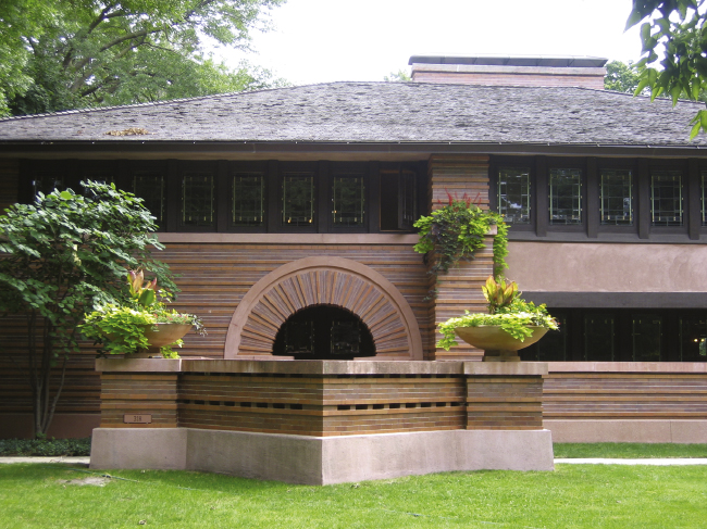
Fig. 8
IIT Campus building in Chicago with the typical Mies van der Rohe corner solution.
7Scenarios of future developments
The outlined technical developmental level shows that the change of functionalities of a massive construction defines the development of the individual constructions. When adding functionalities to increase the performance – the declared goal of any development – the complexity of the construction increases simultaneously: additional layers may allow additional functions but also require more integration of components.
In order to investigate future development the defined functionalities of construction (own weight, thermal expansion, horizontal stress), construction method (process, production, construction), climate control (temperature, humidity, storage capacity, acoustic, light and view), sustainability (embedded energy, usage energy, recycling), usability (safety, fitness for use, maintenance) as well as appearance (urban context, exterior and interior perception) are to be evaluated, and in a second step of the construction development potential additional performance isidentified.
It can, for example, be reflected that in past developmental paths, e.g. after the simple stacking of material for enveloping purposes, the function of insulating in all its variants as well as the function of thermal activation of the construction were integrated. In consequence this means that, for example, besides a mere increase in the functionalities of insulating and load-bearing, a suggestion could be to integrate additional active components of the building technical equipment into the functional area of climate control as potential additional performance.
To further illustrate this issue we will look at another area of the building envelope: in the field of curtain wall systems the developmental steps from post-beam facade to element facade were followed by the stacked second-skin facade. This system was particularly designed to safeguard the sun protection device and to utilise the gap between the glass panes for climate control. A next step in the same direction was to add additional functions to condition the building (cooling, heating, ventilation) by means of building services components that were installed close to the facade – the so-called component facade evolves. Thus, facade systems are paired with building services devices in order to use the building envelope to operate the building (Klein, 2013; Knaack et al., 2007).
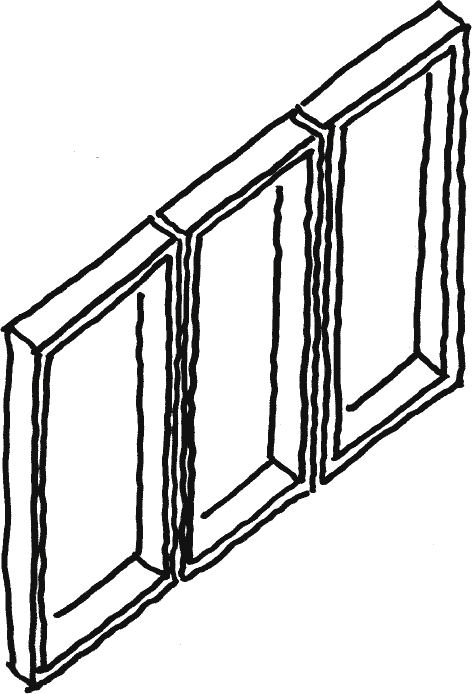
Sketch 38
Element facade.
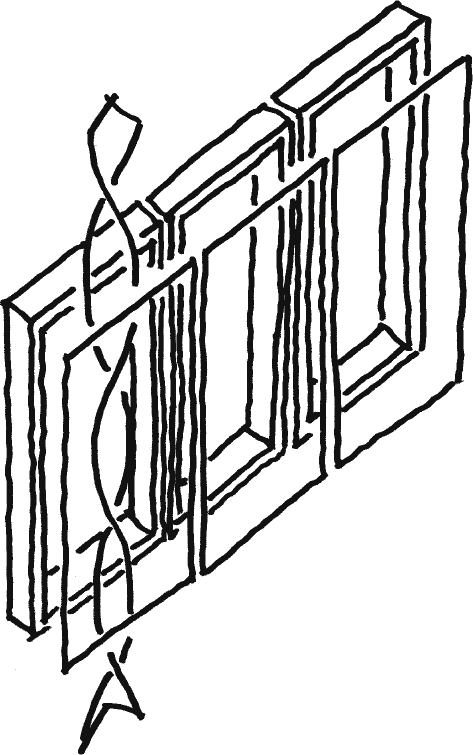
Sketch 39
Double facade.
Sketch 40
Component facade.
By analysing the described development, it appears that the function integration shown in the field of curtain walls can increase the overall functionality of the construction by offering potential for the field of massive constructions as well as by improving the overall performance with the possibility of integrating additional functions.
In parallel two conflicting consequences are to be mentioned: considering the issue of sustainability – also part of the requested functionality – embedded energy, longevity of the construction and its usability after use are aspects contradicting integration: function integration means more complex constructions that are more difficult to dismantle than less integral ones; this is a fact that does not comply with the demand for sustainability. This means that contradictory requirements arise: on the one hand the goal is to integrate more and more functions into the construction, and on the other the construction shall last longer and should be easy todismantle.
In parallel an improvement of the function insulation for a massive construction can influence the capacity to act as load-bearing construction: by increasing the capacity of insulation with more enclosed air in the construction to reduce transmission the construction becomes more fragile. This can only be resolved either with thicker constructions to allow for adequate load distribution, or by an additional structural construction, which in its consequence results in a subtraction offunctionality.
8Integrated active systems
There are two basic strategies to increase functionality: massive constructions must either become lighter and more integral, or layered; alternatively they must be more massive and equipped with functional and separable layers. This trend can be enhanced by integrating active systems into the wall – a concept basically conceivable for both strategies.
The first strategy aims at using little mass in order to minimize embedded energy while still complying with insulation requirements. Hereby, the wall must be considered as one building component which fulfils as many functions as possible. This can be accomplished with an integral model – i.e. with function units arranged side by side/parallel – or as successive layers, whereby the layered functional components may not disturb one another.
Since the goal is to reach maximum functionality, compromises must be made to avoid contradictory technologies – like the described accomplished low mass for a better insulation capacity, the function of load-bearing could be foregone. And purely modular systems seem sensible because integrally designed building components will be complex industrial products that will allow less adaption on site. Another factor to consider is a shorter lifetime of the system solutions since more complex components will reach the end of their useful lifetime earlier. This drives the demand for lighter components to expend less embedded energy, justifying earlier reuse. Following this approach, a concept of integrated active systems is particularly conceivable considering shorter lifecycles and easier replacement/dismantling.
For the second strategy the necessary embedded energy it is to be taking into account: a massive and therefore heavy wall should only be conceptualized with an extended lifecycle. The goal is to develop a construction with the highest degree of possible individuality and adaptability that can be utilized in its basic form but also allows for modifications. It is not targeted to integrate as many functions as possible, but to provide the flexibility to apply those that are wanted/needed for a particular project. Hereby, load-bearing capacity, forming an enclosure and providing storage mass, and insulation are the most important factors. Small, easily shaped units seem to be practical as components – in the shape of liquid materials or small bricks – because this strategy involves using simple components, and it would allow for individual adaptation to a particular shape and structure. In terms of recycling the only goal can be to use as little material mix as possible to maintain low deconstructionexpenditure.
Naturally, a combination strategy is conceivable as well – a massive wall enhanced by layers of lightweight functional units – but in this case the functional units should be easily exchangeable for adaptation whereas the heavier part of the wall remains in place. And it should also be obvious that the scenarios outlined here are extreme solutions; actual developments will certainly be variants and compromised technical solutions, and must – very importantly – take into consideration traditions and market structures.
Additionally, a closer look at the development of integrating active systems has to be taken, i.e. systems for energy production by means of photovoltaic, solar heat, photo bioreactors or simple radiation, the storage options for such energy in building mass or storage elements, for example, water, PCM or batteries, as well as active support for the functions of insulation, ventilation, heating and cooling with building services built-in components. As a concept this strategy is conceivable for both scenarios; it requires however implementation during the concept phase of the construction development. With the lighter weight constructions, designed for a shorter lifetime, these components can be an integral part of the construction. However, if we are dealing with heavier and therefore less integral solutions, the building services components should be conceptualized separately and exchangeable because their lifetime is shorter than that of the wall itself.
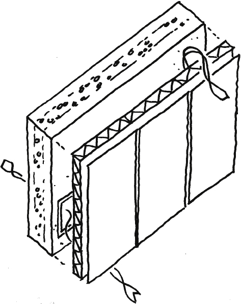
Sketch 41
Light modular massive construction with building services components.
Sketch 42
Lightweight layered massive construction with building services components inside the layers.
Sketch 43
Heavyweight massive construction with integrated areas of lesser density and building services components.
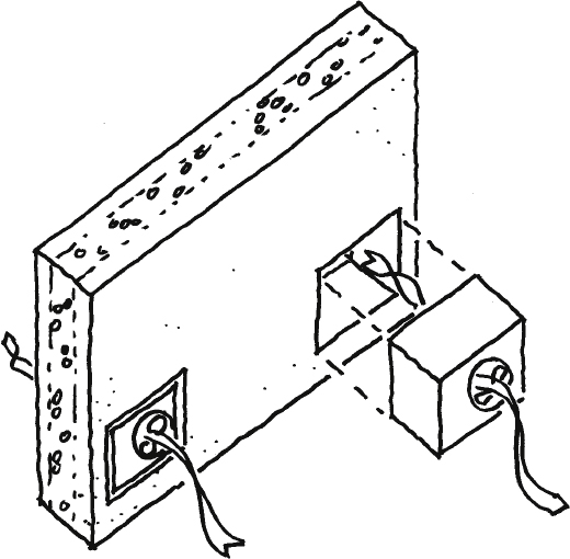
Sketch 44
Heavyweight massive construction with additional building services components within the function layer
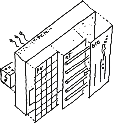
Sketch 45
Energy generation and storage in the massive wall.
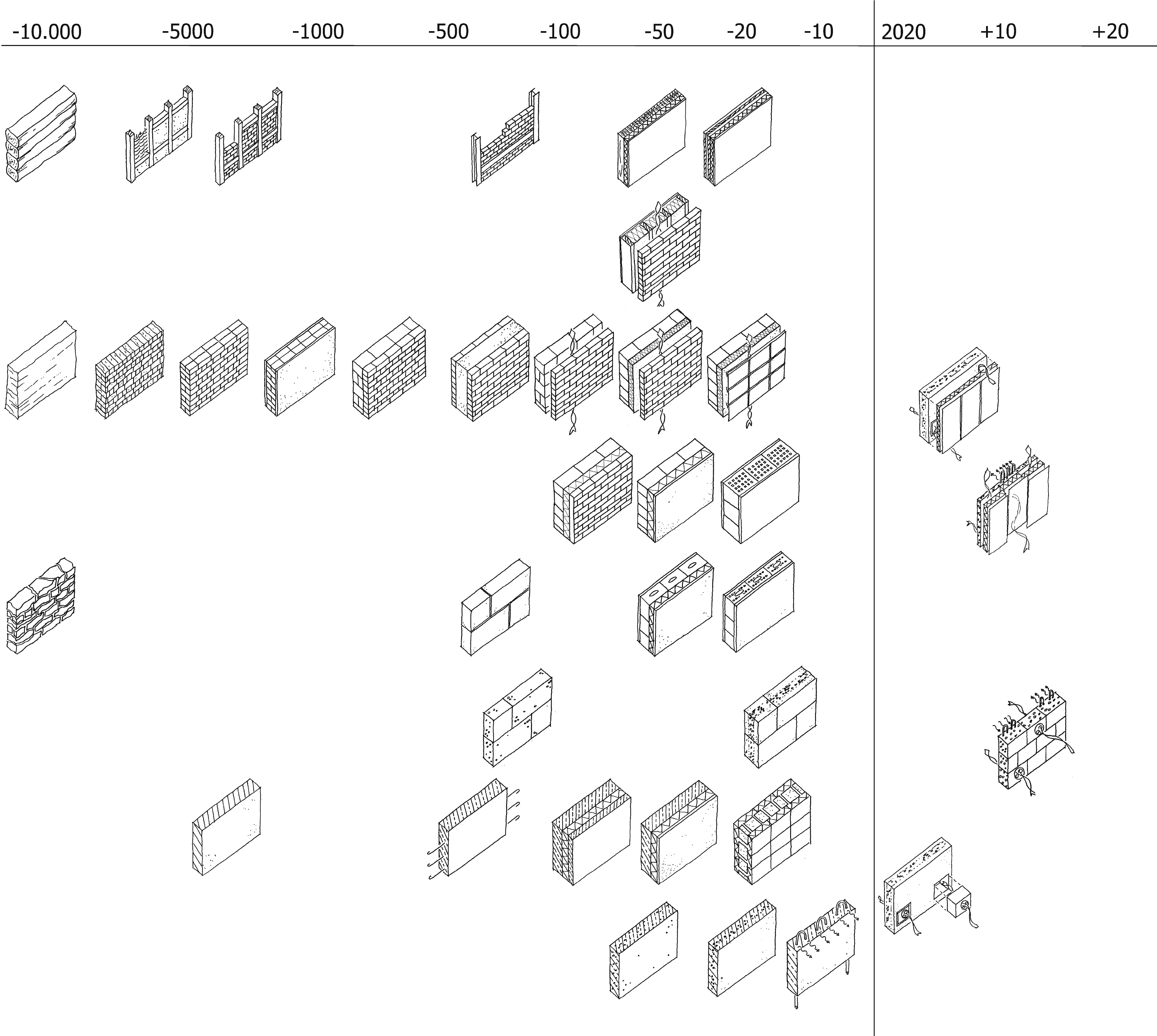
Concluding the investigation of the functional and technical development of the massive construction, the sketches are organised on a roadmap to generate a simpler accessible overview and to allow to visualise their development lines and to express the potential futuredevelopment.
Sketch 46
Overview of massive constructions on a timeline.
9Conclusion
The concept and design phases of the building process are always coined by the discussion of the advantages and disadvantages of more or less complex construction solutions – with the desire for simplicity with equal or better functionality: Michiel Cohen, a representative of Dutch ‘High-Tech architecture’ is known for his quote “The Future has to be simpler” (Knaack, & Klein, 2008). Massive constructions offer the potential of being simple; however that typically implies limited performance – the simplicity of the principle of layering materials or forming and curing them is difficult to supersede. This applies to the flexibility of structural changes made to a massive wall, in terms of construction: brickwork is good-natured, loads can be deflected. It might require structural support; this can easily be accomplished however, unlike with skeletal constructions. Against this background, a massive construction, brickwork in particular, can principally be considered as a conglomerate of individual components that fulfil certain functions. A comparison with the ‘Swarm theory’ or the ‘internet of things’ in the digital world comes to mind: due to their individual but also mostly equal performance many small components allow for a common goal.
References
1 | Achtziger J, Pfeifer G, Ramcke R, Zilch K(2001) Mauerwerk AtlasMünchen, GermanyWalter de Gruyter |
2 | Beim A(2004) Tectonic Visions in ArchitectureCopenhagen, Denmark |
3 | BV-Porenbeton (2013). Retrieved July 22, 2013 from http://www.bv-porenbeton.de/bvp//download/BS_Chronik-Entwicklung.pdf |
4 | Deplace A(2005) ArchitekturKonstruierenBaselBoston/Berlin |
5 | Encyclopaedia Britannica (2013). Retrieved July 7, 2013 from http://www.britannica.com/EBchecked/topic/79195/brick-and-tile |
6 | Kind-Barkauskas F, Kauhsen B, Polónyi S, Brandt J(1995) Beton AtlasDüsseldorf, München, GermanyBeton-Verlag |
7 | Klein, T. (2013). Integral Façade Construction. Towards a new product architecture for curtain walls. Doctoral Dissertation, Delft University of Technology, Faculty of Architecture. (Architecture and the Built Environment 3). Delft, Netherlands. |
8 | Knaack, U. (2011, March). About innovation. Paper presented at the Conference of Adaptive Architecture at The Building C entre, London, United Kingdom. |
9 | Knaack U, Klein T, Bilow M, Auer T(2007) Facades. Principles of ConstructionBaselBoston/Berlin |
10 | Knaack U, Klein T(2008) The Future Envelope 1: A Multidisciplinary Approach8: Amsterdam, NetherlandsIOS Press |
11 | Marti P, Monsch O, Schilling B(2005) Ingenieur-BetonbauZürich, Switzerlandvdf Hochschulverlag AG |
12 | Stacey M(2011) Concrete: a studio design guideLondon, United KingdomRIBA Publishing |
13 | Tafel E(1981) Frank Lloyd Wright persöZürich/MünchenVerlag für Architektur Artemis |
14 | Treiber D(2008) Frank Lloyd WrightBaselBoston/Berlin |


