A completely transparent, adhesively bonded soda-lime glass block masonry system
Abstract
A pioneering, all transparent, self-supporting glass block facade is presented in this paper. Previously realized examples utilize embedded metal components in order to obtain the desired structural performance despite the fact that these elements greatly affect the facade’s overall transparency level. Undeniably, the oxymoron ‘transparency and strength’ remains the prime concern in such applications. In this paper, a new, innovative structural system for glass block facades is described, which demonstrably meets both criteria. The structure is exclusively constructed by monolithic glass blocks, bonded with a colourless, UV-curing adhesive, obtaining thus a maximum transparency. In addition, the desired structural performance is achieved solely through the masonry system, without any opaque substructure. Differing from previous realized projects, solid soda-lime glass blocks are used rather than borosilicate ones. This article provides an overview of the integrated architectural and structural design and discusses the choice of materials. The structural verification of the system is demonstrated. The results show that the adhesively bonded glass block structure has the required self-structural behaviour, but only if strict tolerances are met in the geometry of the glass blocks.
1Introduction
Self-supporting glass block facades have already been realized in several architectural projects as an answer to the continuous quest for a transparent, yet load-bearing barrier between exterior and interior. Three interwoven factors determine the overall structural and at the same time visual performance of a glass block facade: 1) the type of glass blocks used: solid or hollow 2) the choice between the use of a transparent mortar or metal substructure/reinforcement to render the glass wall able to withstand self and wind loading and 3) the form/geometry of the structure.
Glass blocks are commonly produced in a hollow form, fabricated by thermally fusing two shallow rectangular cups along their open faces. A sealed interior air chamber is formed that gives the glass block its thermal and acoustic insulating properties (Murray, 2013, p. 77). Regarding transparency, hollow bricks can be completely colourless. However, the block’s multiple layers (glass – air – glass) result in severe optical distortion of objects observed through it. Figure 1 illustrates how each light ray passing through a block is reflected and redirected within every media, producing a visual obscuration dependant on surface texture and angle of view. Hollow glass blocks are further considered unsuitable as load bearing components due to their relatively low compressive strength value (commonly 2.75– 4.1 MPa (Dietrich, Jerry, & Bruce, 1995, p. 163)). While ceramic masonry bricks with comparable failure loads are used as load bearing elements, the low wall thickness of hollow glass blocks risks internal buckling and failure from the vertical load of the stacked wall; hence the increased risk renders them unsuitable as load bearing components for solid load bearing walls. Thus, a separate supporting structure is required if hollow blocks are used. Usually, in small structures the blocks are embedded in a steel rod reinforced cement-based mortar. In large-scale structures, elaborate metal systems are required to support the structure, utilizing slender opaque elements. Good examples include the Hermes store and the Maastricht Academy of Arts. In the first one, the facade is elevated on a concealed network of thin steel channels, embedded in cavities along the edges of the hollow blocks (Murray, 2013, p. 72). The joints between adjacent blocks are filled with a non-load bearing opaque elastic silicone sealant, whereas in the Maastricht Academy of Arts, the blocks are braced by a slender metal mesh that actually carries all the load (Wiel Architects, 2014).
In contrast, solid glass blocks present a much higher compressive strength, typically over 200 MPa (Beall, 1988; Pittsburgh Corning, 2010; Poesia, 2013), which allows them to be used as loadbearing components, although this requires an absolutely even support surface without any stress raising protrusions; otherwise the blocks can crack locally at low loads which already cause high local stresses at protrusions.
Solid glass blocks are produced by pouring liquid glass into a steel mould. Each block is then cooled down controllably for many hours – duration depending on the dimensions of the block – to avoid cracks due to unequal temperatures between the surface and the core (Christoph & Knut, 2008, p. 113) and to prevent the development of any pre-stress in the block. In comparison to hollow blocks, solid blocks have similar transparency but significantly less optical distortion. Their monolithic mass has a constant refraction index resulting in the redirection of the light rays only at the two external surfaces and hence, causing less distortion of objects projected behind them (see Figure 1). Solid blocks however, have reduced thermal resistance compared to hollow ones. Owing to their inferior thermal insulation properties, as well as to a noticeably higher manufacturing cost and a non-standardized manufacturing process, solid glass blocks have rarely been used for exterior glass walls. Three of the most representative projects utilizing monolithic blocks are the Optical House (Hiroshi, 2012), the Atocha Memorial (Christoph & Knut, 2008) and the Crown Fountain (Hannah, 2009).
As previously mentioned, a supporting structure is required when hollow glass blocks are used in a facade of considerable dimensions because of their insufficient load-bearing capacity. In addition, due to the lack of standardized structural specifications and strength data on transparent adhesives, the majority of projects using solid glass blocks are also dependent on pre-tensioned steel reinforcement to ensure rigidity and prevent buckling. In the Optical House, solid blocks are punctured and threaded from below in a pre-tensioned vertical mesh of stainless steel rods (Hiroshi & NAP, 2013, p. 157). To withstand lateral forces, stainless steel flat bars, embedded within the glass wall thickness, are also strung from the rods at 100 mm vertical intervals. No mortar is used. In the Crown Fountain, a stainless steel frame consisting of T-profiles in the interior of the glass block structure connects to the glass blocks. This frame carries both the weight of the walls and takes up the lateral wind load (Hannah, 2009, p. 11).
Nevertheless, to obtain an entirely transparent visual result, opaque reinforcement elements need to be avoided. The only way to achieve this is by using a transparent adhesive or mortar that can perform structurally. The selected mortar/adhesive should be durable and offer the required short- and long-term bond and compression strength to make the glass masonry wall behave as a single rigid unit against loading.
However, even if a sufficiently rigid masonry system is achieved by the combination of the mechanical properties of bricks and mortar, a masonry wall with a high slenderness ratio can be susceptible to buckling due to self-weight or out-of-plane bending for instance by lateral wind forces. In examples, such as the Optical House and Maison Hermes where steel reinforcement is used, pre-tensioning of the metal elements counteracts buckling and lateral loads. Yet in an unreinforced glass masonry wall these can only be solved through the geometry of the structure. The only glass block structure realized in this way is the Atocha Memorial in Madrid: solid glass blocks bonded by a transparentUV-curing adhesive form a cylindrical tube which contributes greatly to the structure’s rigidity, eliminating the necessity of additional steel elements for its support (Christoph & Knut, 2008, p. 112).
The above studied cases show that for a self-supporting yet completely transparent glass block facade it is necessary to firstly use solid glass blocks that do not require additional supporting elements, secondly to apply a transparent bonding medium to fix and stabilize the blocks, while finally the geometry of the structure also plays an essential role in the overall structural performance (see Figure 2).
In this study the structural behaviour of a novel, completely transparent glass block system consisting of adhesively bonded solid glass blocks is investigated. It is the first time that such a structure will be employed in a flat wall. The overall geometry of the unreinforced glass wall will be crucial so that it can withstand its own weight and lateral forces. Moreover, differing from previous realized projects, blocks of soda-lime instead of borosilicate glass are used.
2Design
2.1The case study
The novel glass masonry system will be realized on the 10 × 12 m facade of the (Crystal House) (see Figure 3), designed by MVRDV and Gietermans & Van Dijk architectural offices. The completion of the project is expected to be accomplished in 2015. Located in the historic Pieter Cornelisz Hooftstraat in Amsterdam, the building had to follow strict planning regulations that required the new facade to maintain the same organization, rhythm and composition as the one of the previous 19th century building. To conform to these restrictions, yet to design an interesting facade, MVRDV came up with an ingenious solution. The Crystal House’s facade is an accurate reproduction of the previous building’s historic facade, yet with one great difference. Instead of brickwork, it is all made of glass: from the bricks to the doors and window frames, everything consists of clear glass. As the facade rises, normal clay bricks intermingle between the glass blocks, to create a smooth, gradient transition to normal brickwork on the top floor. The end result is a building that will stand out, and at the same time will naturally blend into the urban fabric of the historic street.
In principle, the regeneration of the brick facade using glass instead of clay blocks was structurally feasible due to the compression-loading scheme of a wall structure. Considering that annealed glass is usually ten times stronger in compression than tension, it is very suitable as a load-bearing material for such an application. As previously mentioned, the new facade of the Crystal House is composed of solid cast glass blocks that intermix with normal bricks towards the second floor of the building. More specific, the lower ten meters of the facade comprise mainly cast glass blocks. Only at the highest part of this area, the glass blocks intermix with conventional clay bricks in a limited zone until the first array of solely clay bricks appears (see Figure 3). Above this array, a steel beam covered with clay bricks is placed to support the upper, traditional brick facade. The beam is connected to the slab of the second floor, thus allowing for a thicker brick facade (with cavity) to elevate from that point up. At the current stage of research, epoxy is proposed to be used for the connection of the glass block facade with the conventional part of the construction, as well as for the bonding of glass blocks with clay bricks. Nevertheless, this might be modified, since the research for the final selection of adhesives between glass, bricks and steel is at the time of writing still continuing.
To reinforce the flat geometry of the massive glass wall against lateral forces and buckling that may occur due to induced wind eccentricity, four buttresses project inwards from the facade. In specific, the buttresses are 5.5 m tall and are formed by glass blocks interlocking to the ones of the facade, thus forming a continuous relief glass envelope (see Figure 5).
The glass facade, weighs approximately 25% more than a standard masonry facade of the same dimensions due to the higher density of glass compared to brick. This 25% difference of dead load necessitates a reinforced foundation.
Except for the use of glass bricks, the main difference between the old and new masonry system is that the glass wall’s thickness is covered by the width of one brick (210 ± 0.25 mm) instead of two, as in normal masonry (see Figure 5). This was specifically chosen to eliminate unnecessary joints that can affect both the structural and optical performance/clarity of the glass wall. Accordingly, to reproduce the isodomic modulus of the historic brick facade, all glass blocks have the same width (210 ± 0.25 mm) and height (65 ± 0.25 mm) but are cast in three different length sizes (105, 157.5 and 210 ± 0.25 mm).
2.2The glass masonry system
The architectural prerequisite was to obtain a completely transparent and at the same time structurally feasible solution. To meet this requirement, a combination of solid glass blocks and colourless adhesive is used for the fabrication of the glass masonry wall.
In particular, solid glass blocks were selected for their high compressive strength (typically over 200 MPa), which renders them able to carry the dead load of the wall without the need of any supporting structure.
To meet the aim of maximum transparency, a colourless adhesive needs to be used to bond the glass blocks together. The mechanical properties of the chosen adhesive are equally critical to the properties of the glass blocks, as in masonry structures only the properties of the whole structure are important. It is their combination and their interaction as one structural unit that defines the structural performance of the facade and not the individual strength of each element. More specifically the adhesive should:
– be completely transparent and not discolour when exposed to sunlight
– have good short and long term compressive behaviour
– establish high bond strength with glass
– result in a monolithic masonry wall
– provide a rigid structure
– have good resistance to weathering and good aging behaviour
– allow for fast, easy and safe construction
– have no emissions of noxious or poisonous chemicals during processing and curing.
An adhesive that meets all above demands is a one-component transparent, UV-modified acrylate, designed for exterior glass-to-glass bonding. This adhesive is photocatalytically cured and after hardening it becomes moisture- and water-resistant. The specific adhesive reaches its optimum strength when applied in a layer of approximately 0.1– 0.3 mm thickness. Figure 4 illustrates how a comparatively thinner or thicker layer critically affects the adhesive’s shear strength and thus the performance of the adhesive. This means that irregularities on the glass block surfaces can result in an uneven spread of the adhesive which will affect the load-bearing capacity of the wall by creating weak spots. Hence, to obtain the most favourable structural capacity, the glass blocks need to be fabricated with very high dimensional accuracy, to ensure an even and thin distribution of the adhesive. This accuracy is also required for architectural purposes. An inconsistent spread of the adhesive can result in visible gaps and bubbles. But most importantly, considering that the joints between adjacent blocks have virtually zero thickness, even a tolerance of 0.5 mm per block could create a sizeable offset in height or width of the construction. An essential difference between this adhesive system and a conventional mortar system is that mortar can allow for variations in brick dimensions, while this adhesive cannot.
As a result it was determined that the glass blocks’ size and flatness should be confined into a tolerance that can be covered within a homogeneous adhesive layer. This tolerance was found to be ± 0.25 mm in both flatness and dimensions. To verify this tolerance several architectural prototypes were made, on which structural experiments were conducted.
Glass blocks with such strict tolerances in size and flatness have never been asked for or produced before. In projects where metal substructures are used, sealant joints of considerably bigger thickness are used, which can take up the rougher tolerances. On the other hand, in the Atocha Memorial, the sole comparable structure, the overall cylindrical shell geometry that contributes greatly to the structure’s rigidity, allows for a tolerance range of ± 1 mm (Christoph & Knut, 2008, p. 114) without decreasing the structural capacity. However, in this case study the 10 m × 12 m dimensions of the facade and its flat geometry necessitate maximum masonry strength and consequently require optimum thickness of the adhesive.
Soda-lime glass was selected for the casting of the glass blocks, in contrast to borosilicate glass, which until now has been preferred for architectural applications. The reason is that borosilicate glass has a low coefficient of thermal expansion [3.2 – 4 *10−6/K]. As a result, it can resist thermal shocks more easily, reducing thermal expansion to half compared to soda-lime glass [9.1 – 9.5 *10−6/K] (Christoph & Knut, 2008, p. 113). But most importantly borosilicate glass has noticeably less shrinkage on cooling, leading to higher dimensional accuracy of the end product, eliminating most of the need for post-processing. However, in our case, the strict 0.25 mm tolerance requires post-processing even if borosilicate glass would be used. Yet, data from the standardized float and cast production of glass (see Table 1) show that soda-lime glass generally has higher compressive and tensile strength than borosilicate glass. The cast and float manufacturing processes of soda-lime glass lead to closely comparable mechanical properties. With proper processing, the chemical compositions are virtually identical, the glass element is controllably and slowly cooled, while the occurrence of defects such as air bubbles is limited. For example, cast glass objects from either soda-lime or borosilicate have virtually equal strength values compared to floated elements of the same type of glass (values derived from CES EduPack 2014). However, in cast objects of considerably larger thickness, the manufacturing process is more difficult to control and thus the number and size of defects increase. For this case, cast solid soda-lime glass blocks, the strength is expected to be less than given for soda-lime glass in Table 1, but still proportionally better than would be found for cast borosilicate glass.
The custom-made fabrication of the final blocks was assigned to Poesia Company in Italy. The massive blocks are manually cast in specially designed precision moulds coated with nickel, to produce components with smooth surfaces and remove the glass out of the mould more easily. Low-iron glass is used to produce completely colourless glass blocks. Initially, liquid glass, melted at approximately 1200°C is poured into the steel moulds (see Figure 6) and left to cool to 700°C. During this stage, the top face becomes significantly convex due to gravity. After the block is cooled down to 700°C, it is removed from the mould and is placed in an oven to slowly cool down from 700°C to room temperature. The cooling process is time and temperature controlled, lasting from 8 to 36 hours depending on the size of the block, in order to avoid thermal cracking and internal residual stresses. Indeed, measurements done by a Scalp 5 (GlasStress Ltd, 2014) device on specimens indicate that the residual stresses are less than 10 MPa – which is the residual stress limit that the Scalp 5 device can measure. The resultant block is placed in a CNC machine, which removes the convex top face and processes the block to the precise height required. Finally, the two horizontal faces of the blocks are polished to a smooth flat surface, to minimize any local projections of the glass surface that can lead to peak stresses if highly loaded.
Prior and parallel to structural testing, several architectural mock-ups of the masonry wall were built to study the visual performance of the system and to determine the minimum tolerances needed for architectural purposes. Initial research indicated that due to the low viscosity of the specific adhesive, the vertical joints of the blocks cannot be homogeneously bonded: the adhesive would flow downwards before it could be cured. Therefore, it was determined that only the horizontal joints of the blocks would be bonded.
Next, three successive wall mock-ups were made, using blocks of the final custom-made dimensions but with different tolerance ranges. The results are summarized in Table 2. The three mock-ups are shown in Figure 7.
From the results it can be determined that larger tolerances firstly lead to significant offsets in the height and width of the facade, secondly to open joints between adjacent blocks and thirdly and most importantly to an uneven spread of the adhesive that can greatly affect the structural performance of the wall. A satisfactory visual result is only achieved if tolerances of ± 0.25 mm are strictly met in size, rectangularity and flatness.
A fourth mock-up was then constructed (see Figure 8) with the desired tolerance on the blocks, where the construction method of the buttress can also be seen.
2.3Maintenance
The proposed system is practically maintenance free. Glass block is a durable material and generally is not subject to weathering (Dietrich et al., 1995, p. 166). In order to minimize the cleaning requirements of the facade, a spray of hydrophilic coating (e.g. Vindico (Vindico, 2014)) can be externally applied to the wall as a soft coating, so that the rainwater will clean the facade. The coating needs to be re-applied every ten years. To avoid moisture and dust entering the joints of the glass blocks, they are sealed with a moisture- and water-resistant adhesive of the same UV-modified acrylate family, yet with a significantly higher viscosity. This adhesive is also resistant to glass detergents. Both adhesives are aging resistant and do not discolour when exposed to direct sunlight. A wall specimen has been tested in sunlight over a period of six months and neither discolouring nor penetration of moisture has been observed.
3Experimental settings
The interaction between glass blocks and adhesive to create a single structural element defines the structural performance of the masonry. Hence, the actual strength of glass and adhesive are irrelevant, as in masonry structures only the properties of the whole structure are important. Therefore, to apprehend the physical properties of the masonry system, as well as to understand its failure behaviour and verify the tolerances needed in the glass blocks for a better performance, various mechanical tests were conducted on assembled prototypes. It should be noted that the tests were conducted to meet the requirements for data of the structural engineers. Although the number of tests is limited due to the significant cost of each specimen, the data acquired were considered sufficient to meet the requirements for safe structural calculations as required by the local building codes.
The initial experiments for evaluating the structural performance of the glass masonry system were carried out using standard-sized Poesia bricks of 53 × 116 × 246 mm. Only some of the final experiments include bricks of the final sizes.
The standard-sized Poesia bricks have five flat surfaces, which were in contact with the mould, and one up to 0.5 mm convex, which was the exposed to air surface. Experiments were conducted in various configurations to evaluate the degree in which uneven surfaces affect the structural performance of the assembly.
3.1Compression tests
In the primary research stage, four columns were tested in a force controlled hydraulic compression machine, to determine the compression strength of the glass block-adhesive structure as an assembly. The columns comprised standard Poesia blocks of 53 × 116 × 246 mm (specimens A and B) and of 53 × 116 × 121 mm (specimens C and D) that were adhesively bonded together in three different configurations (see Figure 9), to study how the latter affect the strength. Two 18 mm multiplex plates were put at the top and the bottom of each column to prevent the direct contact of glass with metal.
To verify the high compression strength of the final glass blocks, three series of blocks of the custom-made sizes (65 × 210 × 105 mm, 65 × 210 × 157.5 mm and 65 × 210 × 210 mm) were tested in a displacement controlled hydraulic compression machine. The maximum load capacity of the machine was 3 MN. In the first two series of tests, the blocks were placed directly on the machine’s metal surface, while in the third series, two 18 mm multiplex plates were placed between each glass block and the steel surfaces of the compression testing machine. For safety reasons, all specimens were wrapped in several layers of clear PET plastic foil and put in a steel safety cage with polycarbonate windows.
3.2Four-point bending tests
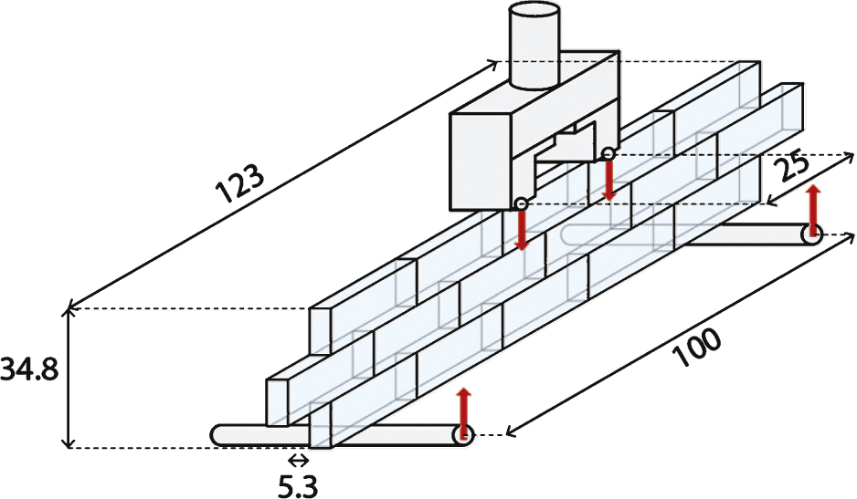
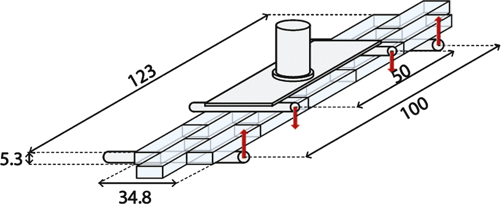
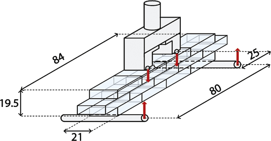
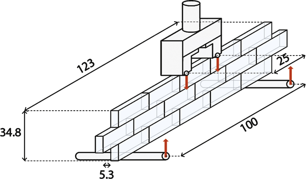
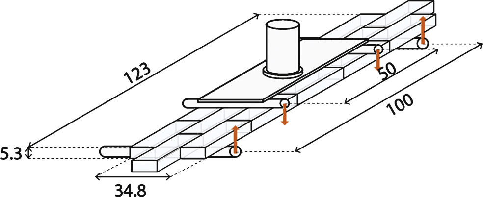
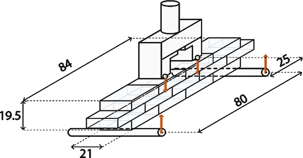
To determine the flexural strength of the glass masonry system, three prototypes were tested in four-point bending until failure in a Zwick Z100 displacement controlled universal testing machine, using a specially fabricated test frame.
All prototypes were made using annealed Poesia solid glass bricks bonded together into a beam by the selected UV-curing adhesive. The specimens had different dimensions and configurations. The initial prototypes, A and B were made using standard sized Poesia bricks (53 × 246 × 116 mm). The last prototype C was made using the final-sized bricks (65 × 210 × 210 mm). To determine both the in- and out-of-plane bending strength of the wall, the specimens were placed either standing or lying in the test frame. The dimensions, configuration and experimental set up of each specimen are summarized in Table 3.
Prior to testing, all specimens were wrapped in several layers of clear PET plastic foil as a safety precaution.
3.3Impact and vandalism test
The glass masonry facade may in actual usage be subject to impact from a variety of causes, such as the accidental impact from bicycles, skateboards, etc., or to the sustained attack with objects such as bottles, bricks, tools etc. in the case of vandalism. Therefore, a rigid body impact test and a vandalism test were performed on an experimental glass wall. The mock-up consisted of 22 glass blocks, each measuring 53 × 246 × 116 mm, which were adhesively bonded to form a wall (see Figure 10). The glass wall mock-up was mounted into a wooden frame, which was fixed to a rigid concrete wall to simulate the inertia conditions of the glass facade. The specimen was not pre-loaded in compression because such an experiment is difficult to set up in a realistic manner and would not produce a reliable result.
First, a hard body impact test was conducted on the specimen. The test was carried out using a solid concrete brick of 65 × 102.5 × 215 mm, weighing 3.4 kg. The concrete brick was placed in front of the facade, touching the target brick. At that position it was suspended with a hook from a 1.5 m long metal wire, hanging down from a wooden cantilever projecting above the mock-up (see Figure 10). The concrete brick, attached to the wire, was then swung outwards by a 45 degrees angle and released from there. The test was repeated two times from a 45 degrees angle, then another two from 90 degrees angle. Afterwards, a vandalism test was carried out on the same experimental wall using a 4 kg sledgehammer until fracture.
3.4Thermal shock test
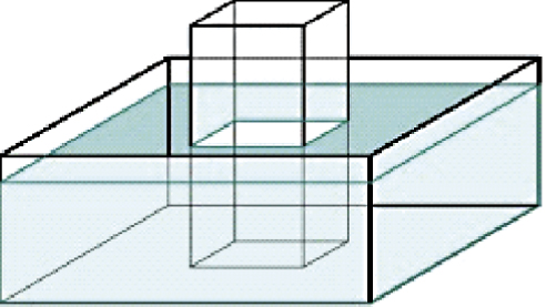
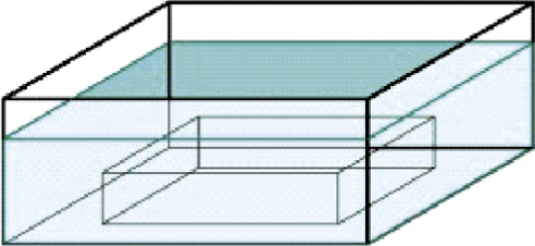
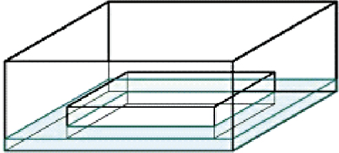
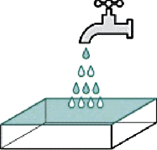
On a warm, sunny day the glass blocks can heat up significantly. In the event of rain on the same day, the warmed glass blocks will come into contact with the colder rainwater and limited thermal shock can occur. The shock intensity is related to the temperature difference between the material and the environment and the rate of heat flow from the glass. In that context, a hot-cold thermal shock is more harmful to glass than a cold-hot thermal shock, because it generates tensile stresses on the rapidly cooled surface. These stresses may be sufficient to activate pre-existing micro-cracks and lead to fracture. Therefore, to evaluate the performance of the glass blocks under peak temperature fluctuations, specimens were heated for four hours in a furnace with a constant temperature of 1) 80°C and 2) 60°C. Then they were cooled down by being immediately immersed into water of 20°C for approximately 10 minutes each. Specimens were (A) half-immersed into water, (B) completely immersed into water, (C) immersed only with one face into the water or (D) splashed on one face. The test set-ups are illustrated in Figure 11.
4Results and discussion
4.1Compression tests
The compression tests of the blocks and columns show that the compression strength of individual glass blocks and of the masonry wall as one structural unit are sufficient to meet the requirements of this design, although the compression strength values of the glass blocks are lower than the ones stated in literature. This can be attributed to the increased amount of interior defects, such as air bubbles, which occur in the casting of such thickness of glass. In a float glass production line, these inconsistencies are avoided through automatic control, but in hand-cast glass they are inevitable. The resulting nominal compressive stresses are summarized in Tables 4 and 5.
The results of the two first series (A, B) of compression tests of bricks, where no intermediary was used between glass blocks and the steel cap of the machine, presented obvious cracks in a compressive stress between 20– 30 MPa, significantly less than the value stated in literature. This is attributed to the high concentrated contact pressure between the stiff glass blocks and the stiffer steel plates of the compression machine (see Figure 12). Any unevenness in the contact surface of the two hard materials induces local peak stresses, which in a brittle material like glass propagate local cracks. This shows the critical importance of properly supporting the glass along the whole surface and not creating any stress concentration in the supports. Therefore, in the third series of compression tests, two 18 mm thick multiplex plates were used as intermediaries on top and bottom of each glass block to ensure an even load distribution (see Figure 12). This demonstrates that the glass blocks can tolerate very high compressive loads. More specifically the smallest block, measuring 210 × 105 × 65 mm, presented its first crack at only 2980 kN load, a load five times as big as the complete dead load of the Crystal House facade, while the other two blocks did not crack until the compressive machine reached its force limit of 3000 kN. This series of experiments emphasizes the importance of designing good connections that optimize the load distribution to the glass masonry wall. Poor detailing or execution can result in high local stresses that significantly reduce the overall strength of the glass structure, while connections that provide a uniform load distribution will result in much higher failure loads. The crack patterns in all broken specimens demonstrate the absence of internal residual stresses in the glass blocks. In specific, no secondary crack branching – an effect of internal residual stress – was observed in any of the specimens, even under high compression loads.
The compression tests of the four glass columns (see Figure 13) revealed significant differences in strength. This can be attributed to firstly the creation of indirect local tensile stresses due to the oblong shape of the specimens, secondly to the different configurations of the glass blocks, and thirdly and most significantly to improper bonding. Indeed, prototypes A and B that presented non-homogeneous bonding demonstrated considerably less strength, up to 50% , than prototypes C and D that were homogeneously bonded. In particular, A and B were adhesively bonded on the largest faces of the standard-sized Poesia bricks. These faces present a convex plane of approximately 0.5 mm at the centre. Thus, the bonding layer is relatively thick and inhomogeneous resulting in a weak joint in the middle of each specimen. In contrast, specimens C and D use a different configuration, where the glass blocks are only bonded on their shorter and much more even surfaces. Accordingly, stronger adhesive bonds were formed and the columns showed a much more monolithic behaviour, resulting in higher compressive strength. Although the samples’ size is limited to derive more general results, they indicate that the compressive strength of the structure is very dependent on the configuration of the blocks and the quality of the bonding surfaces.
4.2Four-point bending tests
The primary four-point bending tests (specimens A and B) indicate an in-plane flexural strength of 7.85 MPa and an out-of plane flexural strength of 9.13 MPa at failure (see Table 6). These results can be used as conservative design values, given the fact that the flexural strength of glass itself is higher. The lower values in fact occur because the beam specimens are only bonded horizontally, resulting to stress concentrations on the open vertical joints, which decreases the strength of the specimen. However, in the actual construction, the glass blocks are confined by the boundaries of the structure and therefore the vertical joints of the wall are prevented from opening and the strength is expected to be higher.
The last specimen was made utilizing glass blocks of 210 × 210 × 65 mm, but from a series that presented considerable intolerances in flatness and height, exceeding many times 0.5 mm, which, given the small thickness of the adhesive, resulted in improper bonded joints. This explains its lower flexural strength (3 MPa) and highlights once more the critical role of the accurate dimensioning of the glass blocks to the overall structural performance of the wall.
4.3Impact and vandalism test
The prototype resisted successfully all impact tests without presenting any cracks; while the concrete brick used as impactor was severely damaged. Accordingly, it is expected that the facade can withstand the accidental impact of normal objects such as bikes, bottles etc.
The vandalism test with a sledgehammer resulted in internal cracks to the aimed glass block, but no damage occurred to any of its adjacent blocks. A second, adjacent block was then hit by the sledgehammer, and the same internal cracking pattern appeared (see Figure 14). The results indicate that 1) a rapid impact force only causes local damage, which does not transfer to adjacent bricks and 2) the damaged blocks still maintain a smooth external surface, hence people do not get hurt if they touch them. It should be noted that an unavoidable by-product of the glass facade is that the glass blocks will already be in high compression due to the self-weight of the structure; thus, they are prone to fail under less load. However, the pre-compression of the blocks is not expected to significantly change the results.
The vandalism test emphasizes the significance of allowing for replacement in case a brick is damaged. A procedure of replacing a damaged brick was developed using the same specimen: first the greatest piece of the damaged block is mechanically removed until only small shards attached to the adhesive are left. The adhesive is then locally heated above 120°C with a hot air blower. This is the transition temperature where the adhesive starts to become viscoelastic and softer, allowing for easy mechanical removal of the last glass shards and of the adhesive layer itself, without damaging the adjacent blocks. A new glass block, machined down by 0.1 mm in dimensions to slide easily into the empty slot, can be then inserted (see Figure 15). Adhesive can be injected into the surrounding seams, using a syringe.
4.4Thermal shock tests
The results of the thermal shock tests are summarized in Table 7. Specimens C and D are the closest simulation of the hot facade’s resistance against summer rain, since in the event of rain, only the external surface of the blocks will be exposed to rainwater. In none of these specimens appeared any cracks. However, all specimens that were half or completely immersed into water after being heated to 60°C or 80°C presented considerable cracks in their interior due to the abrupt temperature change between the surface and the core. More specifically, both samples B developed internal cracks in all of their volume, while in specimens A cracks were generated only in the part that was immersed in water (see Figure 16). In that case, a clear, almost horizontal cut marks the waterline. In both A and B samples, the cracks continued to grow significantly after they were removed from the water. The results suggest that the blocks can withstand the elements if applied in an external building wall such as the case study, where they will be susceptible to a rapid temperature change mainly on their external surface. Nonetheless, the blocks may be susceptible to damage in locations with extreme weather conditions. If the concept is to be used in a less moderate climate than Amsterdam, it is recommended to test for thermal shock using appropriate parameters.
5Conclusions
An innovative, self-supporting glass masonry wall system, consisting of annealed soda-lime solid glass blocks bonded together by a UV-curing, colourless adhesive has been introduced in this paper. Applied on the Crystal House facade, the structural solution is a remarkable demonstration of glass’s structural performance; a self-bearing wall of considerable dimensions can be obtained that at the same time preserves an optimum level of transparency.
The experimental work done proves the structural feasibility of the particular case study. Specifically, the facade meets the structural requirements set by the engineering team and the local building authorities. The experimental results indicate that the structure acts monolithically against loading, offering compressive and flexural strength comparable to or better than the strength of typical B80 high performance concrete. In particular, the structural system applied on the Crystal House facade allows for a glass wall of considerable dimensions that can withstand its own weight without cracking or buckling. The flat geometry of the facade and its high slenderness ratio necessitate the reinforcement of the facade against lateral forces and buckling that may occur due to eccentricity induced by wind. This is done by the four 5.5 m tall buttresses on the inner side of the glass wall. In this way a completely transparent solution is achieved using the geometry of the facade, sparing the necessity of additional non-transparent steel elements.
Even though in soda-lime glass the thermal stresses occurring are much higher than for borosilicate glass, the experiments show that soda-lime glass blocks can withstand normal rapid temperature changes when applied to an external wall in a temperate climate. The impact and vandalism tests demonstrate that the Crystal House facade can remain intact against accidental impacts of objects but is susceptible to vandalism. This shows the need of a replacement method in case of a damaged element, which was successfully developed and experimentally proved.
The compression and four-point bending tests show that first, improper connections of the wall with the rest of the building and secondly, non-homogeneous bonding will greatly affect the overall structural performance of the masonry system. This emphasizes the significance of thorough connection design and skilled application, but most essentially it stresses the importance of strict tolerance specifications in the brick fabrication in order to achieve a uniform application of the adhesive. The experiments show that, to ensure a consistent and optimum structural and visual performance, the glass components’ dimension tolerances should not exceed ± 0.25 mm deviation in size and flatness (see Figure 17). On the facade as a whole, this means that the size deviations will be limited to a few millimetres. This requirement for ‘extreme’ accuracy glass blocks reveals the level of complexity of the fabrication process. Several consecutive innovative steps had to be made by Poesia Company in order to manufacture blocks that comply with the required strict accuracy in size and quality.
Overall, this work consists of pioneering research, resulting in a novel and innovative structural system with optimum transparency, proving once more the potential of glass as a structural material. Although the experiments and research presented were conducted for the specific case study, the results indicate the potential of developing a methodology for the solid glass block system, so that it can be further applied to other projects.
Acknowledgments
The project was done as research for Ashendene-Leeuwenstein BV whose permission to publish the results is gratefully acknowledged. MVRDV and Gietermans & Van Dijk are responsible for the architectural design. We thank Ashendene-Leeuwenstein BV for the 3-D impressions of the case study and Poesia Company for the images of the moulds. We also thank Rob Janssen from Siko BV for his valuable advice and assistance.
Reference
1 | Beall C(1988) Glitzy, Glowing, Glamorous Glass Block: How Does Glass Block Perform?Masonry Construction |
2 | Christoph, P., & Knut, G. (2008). Innovative Glass Joints – The 11 March Memorial in Madrid. Paper presented at the Challenging Glass: Conference on Architectural and Structural Applications of Glass, Delft, The Netherlands. |
3 | Den Ouden G(2009) LastechnologieThe NetherlandsVSSD |
4 | Dietrich N, Jerry S, Bruce K(1995) Glass BlockThomas JTwentieth-century building materials: History and conservation163167McGraw-HillNew York, NY |
5 | GlasStress Ltd. (2014). GlasStress Ltd. Retrieved 18-11-2014, from http://www.glasstress.com/ |
6 | GRANTA (2014). GRANTA Material Intelligence. Retrieved 20-11-2014, from http://www.grantadesign.com/education/ |
7 | Hannah BH(2009) Jaume Plensa: Crown Fountain as CarnivalesqueUSA: ProQuestUmi Dissertation Publishing |
8 | Hiroshi N(2012) Optical glass houseArchitectural Review4045 |
9 | Hiroshi N, NAP (2013) Residence in hiroshimaDETAIL: Translucent and Transparent2: 157 |
10 | Murray S(2013) Translucent building skins: Material innovations in modern and contemporary architectureLondonRoutledge |
11 | Pittsburgh Corning(2010) architectural Glass Block ProductsU.S.A.Pittsburgh Corning Corportation |
12 | Poesia(2013) the glass side of lifePoesiaItaly |
13 | Riewoldt (2014). Riewoldt - adhesion - cutting - die cutting/Knowledge center. Retrieved from http://www.riewoldt.de/en/knowledge-center/fundamentals-of-adhesive-technology/ |
14 | Schittich C, Staib G, Balkow D, Schuler M, Sobek W(2006) Glass Construction Manual2nd revised and expanded edition edBasel, SwitzerlandBirkhäuser |
15 | Vindico (2014). Vindico Retrieved 15/11, 2014 http://www.vindico.info/ |
16 | Wiel Architects (2014). WAA Academy of Art & Architecture. Retrieved 20-08-2014, from http://www.wielaretsarchitects.com/en/projects/academy_of_art_amp_architecture/ |
Figures and Tables
Fig.1
The transition of the light rays through multiple media in a hollow glass block results in much more distortion compared to a solid glass block.
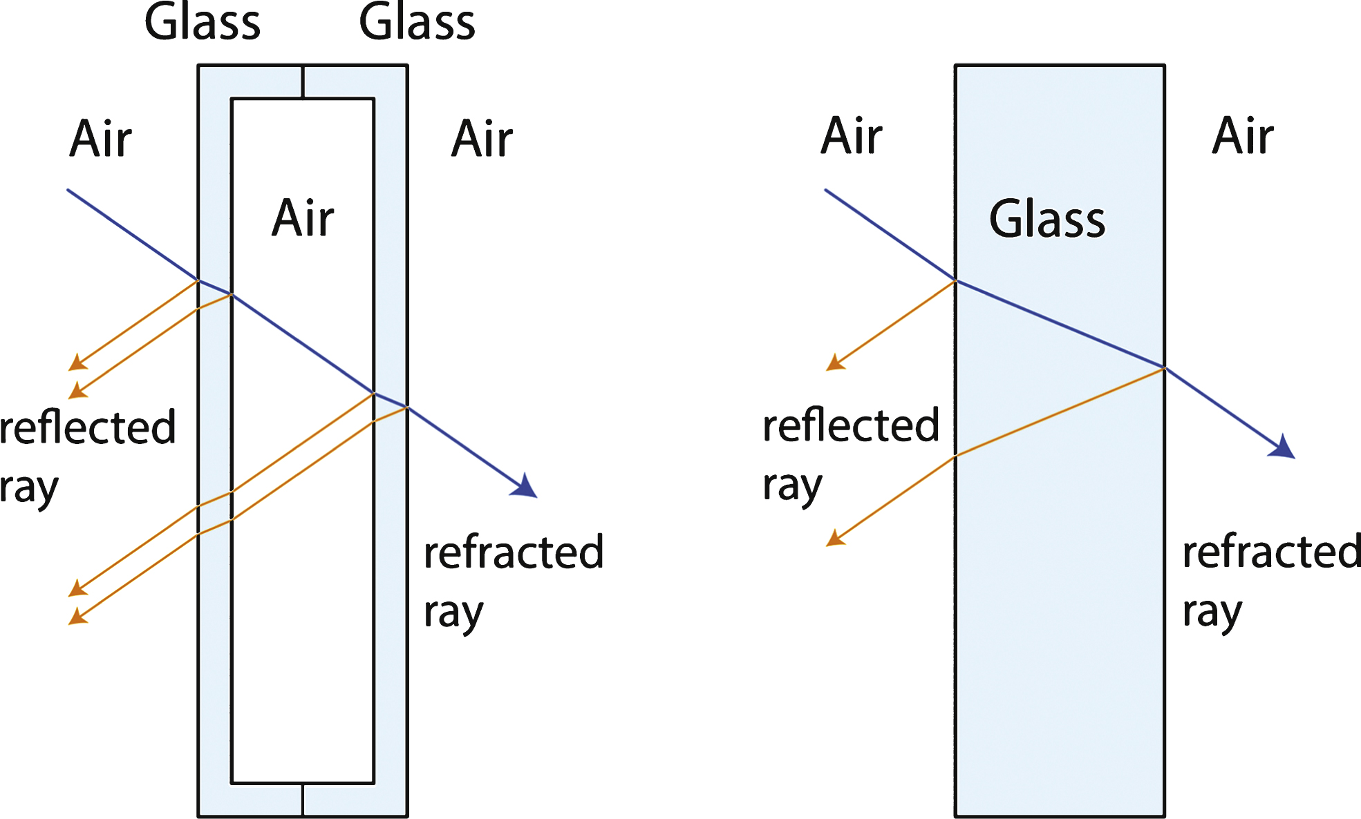
Fig.2
Prerequisites for a completely transparent, structurally efficient glass block facade.
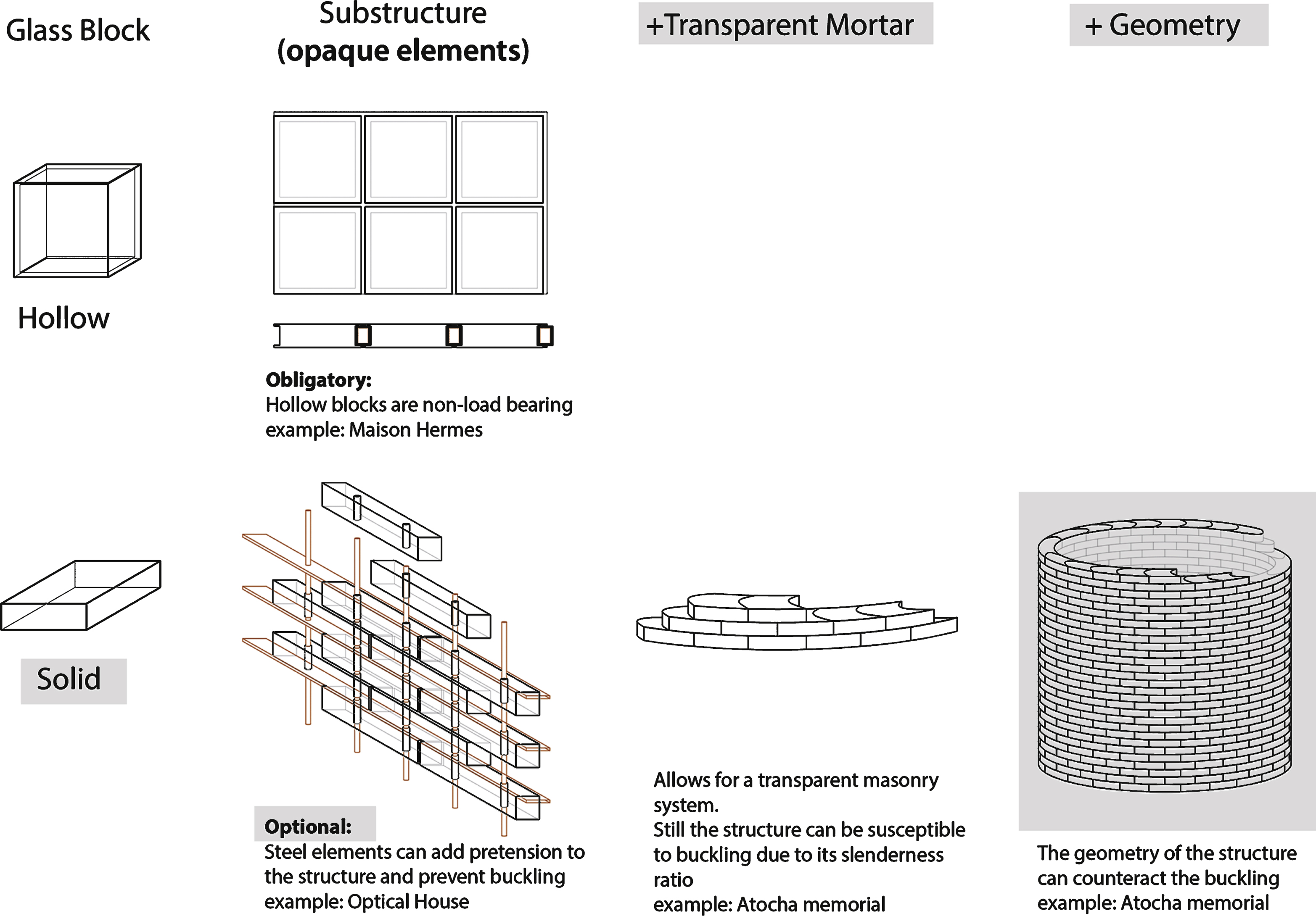
Fig.3
3-D impressions of the glass block facade for the Crystal House in Amsterdam.
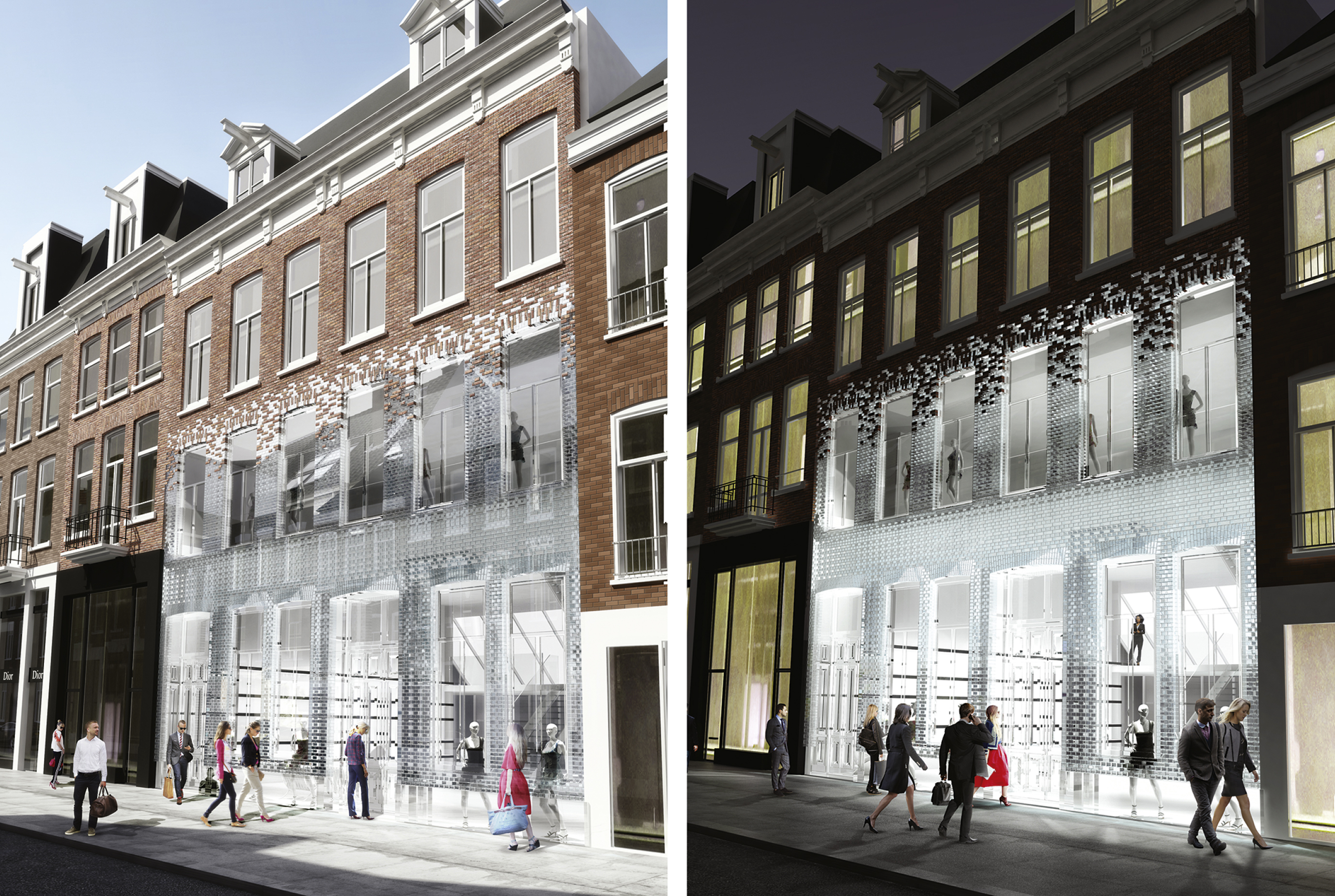
Fig.4
Schematic Illustration of the relation between the optimum strength and the thickness of adhesive (Den Ouden, 2009; Riewoldt, 2014).

Fig.5
Basic structural scheme of the proposed system.
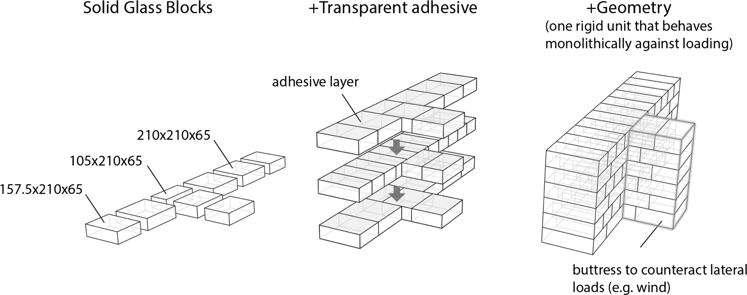
Fig.6
Top: Casting of the soda-lime glass blocks by Poesia Company, using preliminary moulds. Bottom: Final precision moulds.
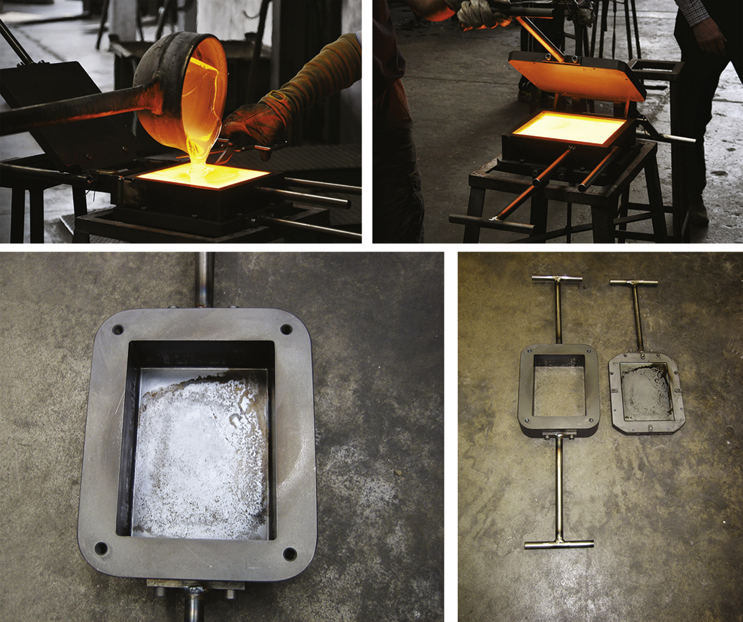
Fig.7
Photographs of the three mock-ups. The first mock-up (A) was made with larger tolerances. As a result there were significant offsets in both height and width and also open joints between blocks. Centre: Mock-up (B). Higher accuracy in the size of the blocks counteracted the offset. Nevertheless, an unevenness of up to ± 0.5 mm in flatness resulted in cavities and bubbles in the bond layer. Right: Mock up (C). All blocks meet the ± 0.25 mm tolerance, resulting in an even spread and thus homogeneous bonding with an optimum visual result with no cavities or bubbles.

Fig.8
Photographs of the final mock-up which includes the buttress’s construction by interlocking glass blocks.

Fig.9
Illustration of the three different column configurations.
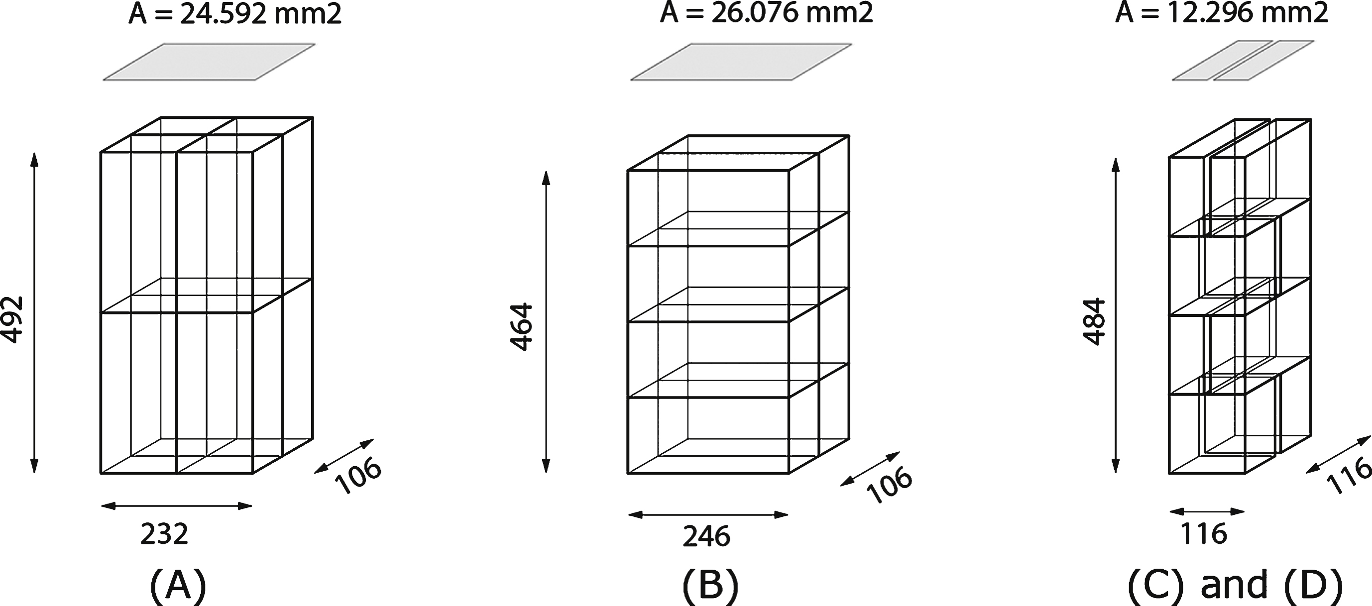
Fig.10
Impact and vandalism test set-up.
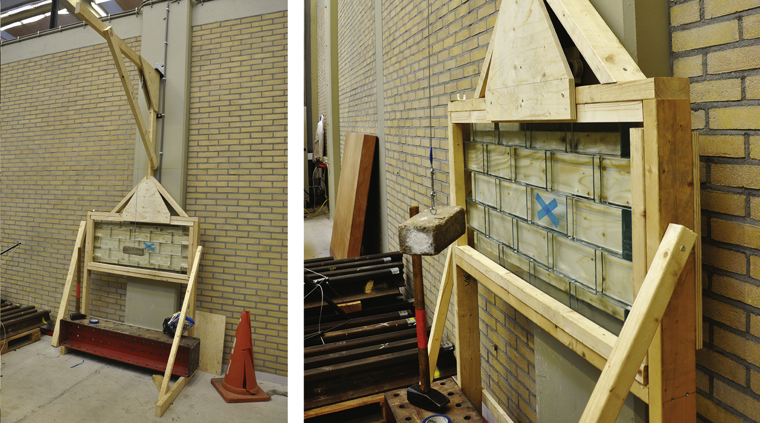
Fig.11
Illustration of the thermal shock set-ups.

Fig.12
Compression tests of glass blocks. Left: Test set-up for the two first series of blocks. Middle: Test set-up for the last series of blocks. Right: Typical initial crack pattern in specimen.

Fig.13
Compression experiment of the columns.

Fig.14
Left: Results of the first vandalism test. Right: The vandalism test was then repeated to an adjacent brick. Only the aimed block was damaged.

Fig.15
Left: The prototype before replacement. Right: The prototype after replacement of one of the damaged blocks.

Fig.16
Specimens A and B tested in thermal shock from 80 to 20°C. Left: Cracks in the specimens right after they were removed from the water. Right: Growth of the cracks in the same specimens the next day.

Fig.17
Final mock up made by glass blocks with 0.25 mm precision in dimensions.

Table 1
Properties of standardized float/cast soda-lime and borosilicate glass
| Units | Soda-lime | Borosilicate glass | |
| Thermal resistivity | [m*°C/W] | 0.909– 1.11 | 0.769– 0.909 |
| Thermal expansion coefficient | 10−6/K | 9.1– 9.5 | 3.2– 4 |
| Tensile strength | MPa | 30– 35 | 22– 32 |
| Compressive strength | MPa | 300– 420 | 260– 350 |
| Young’s modulus | GPa | 68– 72 | 61– 64 |
| Hardness | kg/mm2 | 440– 485 | 84– 92 |
| Cost | € /kg | 1160– 1370 | 3430– 5150 |
| Typical Chemical Composition | 73% SiO2 | 80% SiO2 | |
| 17% Na2O | 4% Na2O | ||
| 5% CaO | 13% B2O3 | ||
| 4% MgO | 2.3% Al2O3 | ||
| 1% Al2O3 | 0.1% K2O |
*Properties derived from the Glass Construction Manual (Schittich, Staib, Balkow, Schuler, & Sobek, 2006) and CES Edupack 2014 Program (GRANTA, 2014).
Table 2
Architectural mock ups
| Mock-up | Tolerances | Remarks | |||
| rectangularity [mm] | height [mm] | width [mm] | flatness [mm] | ||
| A | ±0.5 | ±0.5 | ±0.5 | ±0.5 | – The inaccuracy in rectangularity leads to open joints of up to 5 mm.
– Considerable offsets in both height and width of the prototype – Inconsistency in bonding surface |
| B | ±0.25 | ±0.25 | ±0.25 | ±0.5 | – No offset in height and width of the prototype – Inconsistency in bonding surface: bubbles, gaps, unsatisfactory optical result |
| C | ±0.25 | ±0.25 | ±0.25 | ±0.25 | – No offset in height and width of the prototype – Uniform distribution of the adhesive, satisfactory optical result. |
Table 3
Specimen and 4-point bending test configurations
|
Specimen A Test: In-plane bending Standing Position Specimen size: Span: 123 cm Width: 5.3 cm Height: 34.8 cm |
|
Specimen B Out-of-plane bending Span: 123 cm Width: 34.8 cm Height: 5.3 cm |
|
Specimen C In-plane bending Span: 84 cm Width: 21 cm Height: 19.5 cm |
Table 4
Results of glass blocks’ compression tests
| Specimen | Dimensions [mm] | Load where first crack became visible [kN] | Nominal stress where first crack became visible [MPa] |
| Small brick | 210 × 105 × 65 | - (A) 500 (B) | - (A) 22.7 (B) |
| Small brick with wood bases | 210 × 105 × 65 | 2977 (C) | 135 MPa (C) |
| Medium brick | 210 × 157.5 × 65 | 999 (A) 870 (B) | 30.2 (A) 26.3 (B) |
| Medium brick with wood bases | 210 × 157.5 × 65 | >3000 * (C) | >xx (C) |
| Large brick | 210 × 210 × 65 | 1248 (A) 882 (B) | 28.3 (A) 20 (B) |
| Large brick with wood bases | 210 × 210 × 65 | >3000 * (C) | >xx (C) |
*Maximum load capacity of the displacement controlled hydraulic compression machine, where the specimens were tested. No cracks were observed up to that load in these two specimens.
Table 5
Results of glass columns’ compression tests
| Specimen | Dimensions [mm] | Failure load [kN] | Nominal failure stress [MPa] |
| A | 232 × 106 × 492 | 2090 | 85 |
| B | 246 × 106 × 464 | 1296 | 49.7 |
| C | 116 × 121 × 484 | 1597 | 113.8 |
| D | 116 × 121 × 484 | 1484 | 105.7 |
Table 6
Results of 4-point bending tests
| Specimen A | Specimen B | Specimen C |
|
|
|
| Block size: 53 × 116 × 246 mm | Block size: 53 × 116 × 246 mm | Block size: 65 × 210 × 210 mm |
| Adhesively bonded only in the 53 × 116 faces (horizontal joints) | Adhesively bonded in the 53 × 116 faces (vertical joints) | Adhesively bonded in the 210 × 210 faces (horizontal joints) |
| Failure load: 44800 N | Failure load: 11900 N | Failure load: 29500 N |
| σ flex = 7.85 MPa | σ flex = 9.13 MPa | σ flex = 3.05 MPa |
Table 7
Results of thermal shock tests
| T. | A
| B
| C
| D
|
| 60°C | Interior cracks only at the part that was into the water. | Completely cracked in the interior. | No cracks | No cracks |
| 80°C | Interior cracks only at the part that was into the water. | Completely cracked in the interior. The cracks | No cracks | No cracks |
| The cracks are more severe than in 60°C. | are more severe than in 60°C. |


