Probabilistic risk analysis of local verification of Load Model 1 in Eurocode for Soil-Steel Composite bridges in Sweden
Abstract
Bridges must be designed to ensure safety for all users. At the same time, the design should be performed with an appropriate risk level. In Sweden, Soil-Steel Composite bridges (SSCB) are the most common bridge type. For SSCB, local verification of Load Model 1 in Eurocode is most often governing the design. The objective of this study was to investigate whether local verification of LM1 load case could be modified without decreasing the agreed risk level in Eurocode. Weight in motion measurements from real traffic were extrapolated with Rice formula. Monte Carlo simulations were used to simulate the 1000-year return period event to obtain the acceptable risk level as prescribed in Eurocode. The results show that the local verification of LM1 is conservative, considering the acceptable risk level in Eurocode. With a modified implementation of local verification, this paper shows that a potential saving of up to 14% in terms of economic cost and CO2-equivalents is possible. A modified implementation of local verification of LM1 in Eurocode for SSCB is proposed, which could reduce the climate impact by up to 14% associated to the construction of new SSCB in Sweden.
1Introduction
It is a well-established fact that the construction industry is responsible for a great share of the world’s used natural resources and is a large contributor to global greenhouse gas emissions. The transport infrastructure is a fundamental part of society that affects many people and greatly impacts the environment. Bridges represent an important part of that infrastructure, but also a part that has the potential to reduce its climate impact by more optimized structural design. It is crucial that bridges are designed for loads that ensure their safety; however, the design should not be too conservative since this will increase material usage and, consequently, cost and climate impact.
Sweden has a long-term goal to reach zero net emissions from CO2-equivalents by the latest 2040 [1], while the Swedish Transport Administration (STA) has defined three milestones to reach this goal: a 30% reduction by 2025, a 60% reduction by 2030 and an 80% reduction by 2035 with respect to the CO2 emissions of 2015 [2].
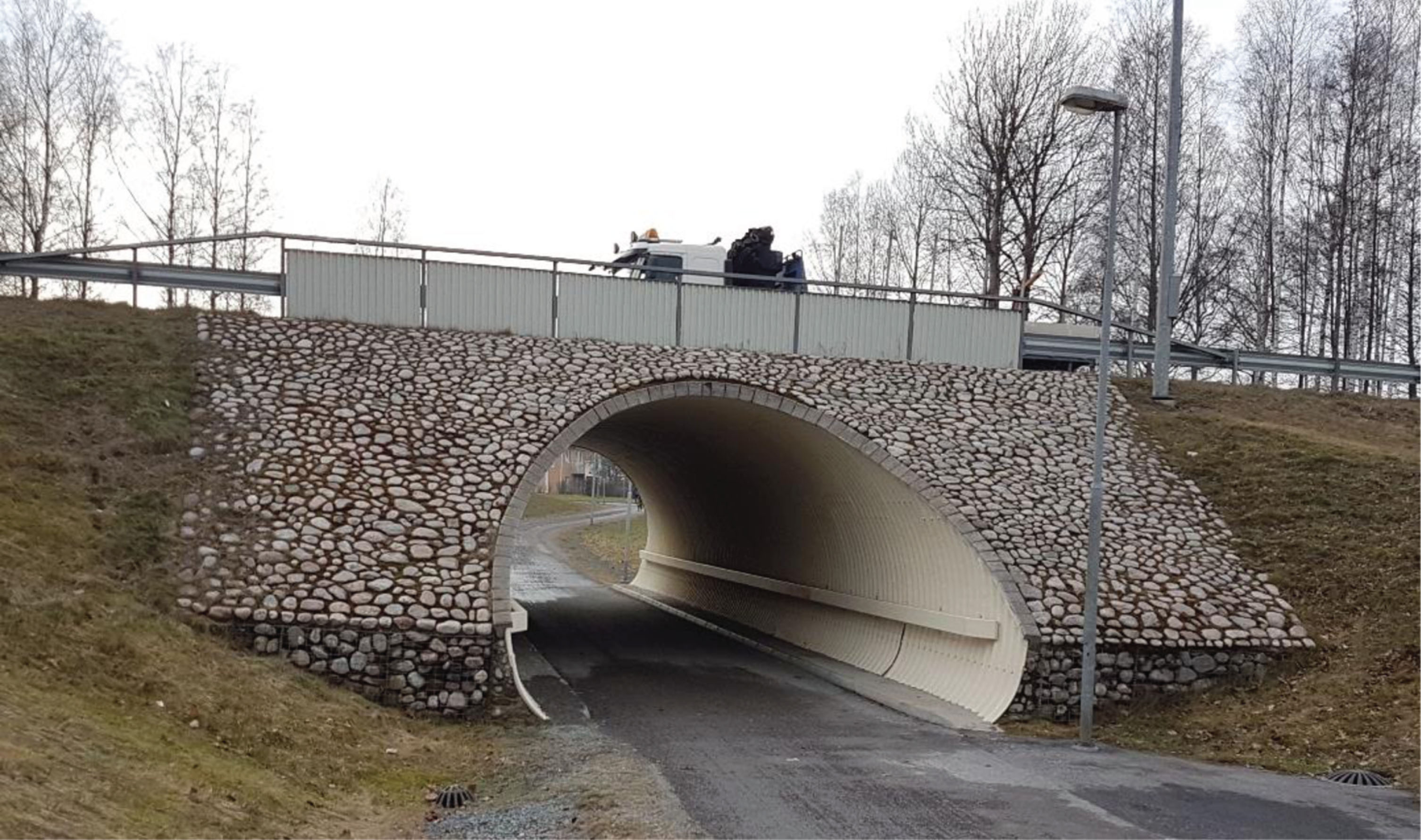
Since the implementation of Eurocode (EC) in Sweden in 2010, Soil-Steel Composite Bridges (SSCB) are the most commonly built bridge type in Sweden [3]. SSCB are flexible culverts that are made from corrugated steel plates exhibiting composite action with the surrounding soil, see example of a SSCB in Fig. 1.
Fig. 1
Soil-Steel Composite Bridge over a pedestrian walkway in Lidköping, Sweden.
From the beginning of 2010 and up to the first half of 2021, a total of 522 SSCB were built in Sweden, corresponding to 31% of all the bridges built during that period [3]. Although SSCB are often used for smaller passages, such as bridges over a creek or to cross a pedestrian road, previous research has shown that SSCB are also a viable solution for larger spans [4]. Furthermore, SSCBs are often an attractive structural solution from an economic and construction time standpoint compared to reinforced concrete slab frame bridges, which are also a common type of bridge in Sweden. Nevertheless, neither solution can be regarded as clearly better than the other from an environmental perspective, since contradictory results can be found in the literature [5, 6].
In recent years, numerous research studies have been conducted aimed at minimizing the cost and climate impact of construction through optimization of the structural design. Yavari et al. optimized slab frame bridges with regard to environmental impact [7] and investment cost [8]. Instead of optimizing with regard to environmental impact and investment cost separately, numerous studies have used multi-objective optimizations considering both economic cost and environmental impact [9–12]. Other studies have investigated the applicability and performance of different optimization algorithms [13–16]. Another way of optimizing bridges is by studying the optimal shape of the structure, which has been done through topology optimization [17–19]; all these studies have shown a potential to decrease the amount of material used in the structures, thereby also decreasing the cost and environmental impact. However, all the previously mentioned optimizations will reach a maximum in the end, and then it will not be possible to optimize the structure anymore with that method.
Another step would then be to study the load effects from the loads that the bridges are designed for and compare these to the load effects from real traffic. By carrying out a probabilistic risk-based assessment of the traffic loads on SSCB, as previously done on other bridges in [20–22], it would be possible to determine whether the current design loads can be modified and still fulfill the acceptable risk level as specified in Eurocode. By designing the bridges for the acceptable risk level, unnecessary oversizing could be prevented, leading to a potential decrease of the amount of material. However, to the best of the authors’ knowledge, none of the available studies have investigated the indirect potential optimization of material by comparing actual measured loads acting on the bridges with the loads that the bridges are designed for. This study fills this gap by studying how probabilistic risk analysis could be used to foster economic and climate (in terms of CO2-equivalent) savings for SSCB in Sweden. This study aims to compare design loads given in Eurocode with measured traffic loads in Sweden and, in turn, propose modification of local verification of Load Model 1 as recommended in Eurocode.
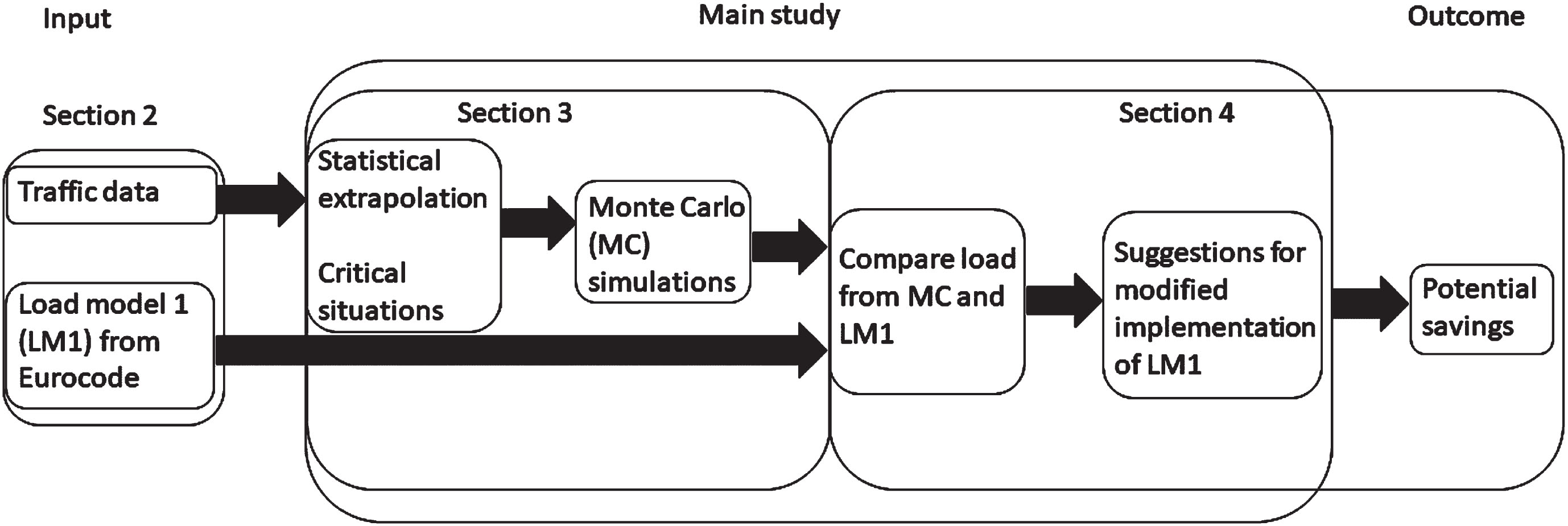
An overview of the paper is presented in Fig. 2. In section 2, the input that is used in the study is presented. In section 3, the method using Monte Carlo simulations on design critical situations is presented. In section 4, results from the Monte Caro simulations are compared to the effect from Load Model 1. The results from the comparison are then used to give suggestions for a modification of Load Model 1, which could give potential savings in terms of less material used.
Fig. 2
Overview of the paper.
2Traffic loads
This section deals with two parts, the first one presents the load models from Eurocode, and the second one presents measured traffic data (the measurement was not part of this study).
2.1Load models
According to the Swedish bridge design code [23], all new bridges in Sweden should be designed for traffic loads according to Eurocode 1, part 2 [24]. The design according to EC is based on the distribution of the 50-year maximum, and the characteristic load is calculated as the value with a 5% probability of being exceeded in this time period, or 10% in 100 years. This is approximately equivalent to the return period of the characteristic load of 1000 years according to [25–27].
The design of SSCB was made according to [28], where design criteria in Ultimate Limit State (ULS), Serviceability Limit State (SLS), Fatigue (FAT) and design checks during construction should be verified. For bridges that should be used for road traffic, Load Model 1 (LM1) and Load Model 2 (LM2) according to [24] should be considered in the design. In addition, bridges in Sweden should be designed for a set of 14 typical vehicles, “Typfordon”, according to [29]. However, these vehicles are often less restrictive than LM1 and LM2 for SSCB, which was observed by [28].
LM1 is represented by a vehicle consisting of two axles with 1.2 m between the axles and 2.0 m between the wheels. The contact area of the wheels is 0.4×0.4 m, see Fig. 3(a). For a road width > 6.0 m, EC specifies that two vehicles are to be placed next to each other with a distance of 1.0 m between the center of their closest wheels. The load magnitudes are referred to as αQiQik, where αQi is a national adjustment factor and Qik is the characteristic axle load, which is 300 kN in the first lane and 200 kN in the second lane (i = 1 and 2 respectively). LM2 is represented by a single axle load βQQak, where βQ is an adjustment factor and Qak is the characteristic axle load, which is 400 kN. The distance between the wheels is 2.0 m, and the contact area of the wheels is 0.35×0.6 m, see Fig. 3(b). The adjustment factor αQi used in Sweden is 0.9 for lane 1 and 2 [29], and the βQ factor is the same as the αQ1 which is recommended in EC.
For LM1, a load case with local verification is often the critical design case for SSCB. In this load case, two vehicles are brought closer together, with a distance of 0.5 m between the center of the wheels. With regard to the width of the wheels for LM1, this load case would represent that the two vehicles are standing with a distance of 0.1 m between the edges of the wheels as illustrated in Fig. 4. In this scenario both vehicles are driving closer to the middle of the bridge, instead of centric in their respective traffic lanes, which is the normal case for LM1.
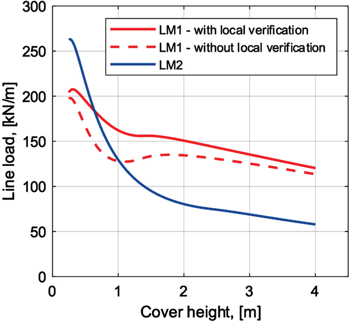
When studying the effects from LM1, with- and without local verification, and LM2 for SSCB, Fig. 5 shows that LM2 is often critical for smaller cover heights, whereas LM1 with local verification is critical otherwise. Similarly, Fig. 5 also shows that the critical load for SSCB could be reduced if the requirement for local verification was modified for these bridges.
Fig. 5
Line loads from LM1 with- and without local verification and from LM2.
2.2Measured traffic data
For this study, Weight in motion (WIM) measurements performed in Sweden during 2020 at a bridge located around 800 m west of “Ölandsbron” at the main land side were used. A total of 21 days of measurements were collected which were performed in three separate occasions, lasting seven days each. For this study, the speed, weight of every single axle and number of axles from all the heavy vehicles were used, where a heavy vehicle is considered when the registered gross weight is above 3500 kg. Table 1 summarizes the number of heavy vehicles counted during the three measurement periods. The measurement periods were chosen to represent the real traffic load during a year. It is worth repeating that the measurements were not part of this study, and the chosen periods were nothing we could influence. The measurements performed in 2020 were a follow up from a previous set of measurements carried out during 2007, the results of which can be found in [30]. For this study, information regarding the vehicles’ position in their respective traffic lanes was not available. Therefore, the probability distribution for the positions in the traffic lane from the WIM measurements performed in 2007 was adopted for this research.
Table 1
Number of heavy vehicles and their corresponding period of measurements during 2020
| Year | Period of | Number of |
| measurements | heavy vehicles | |
| 2020 | May 7–13 | 4 620 |
| 2020 | August 20–26 | 5 238 |
| 2020 | October 16–22 | 4 786 |
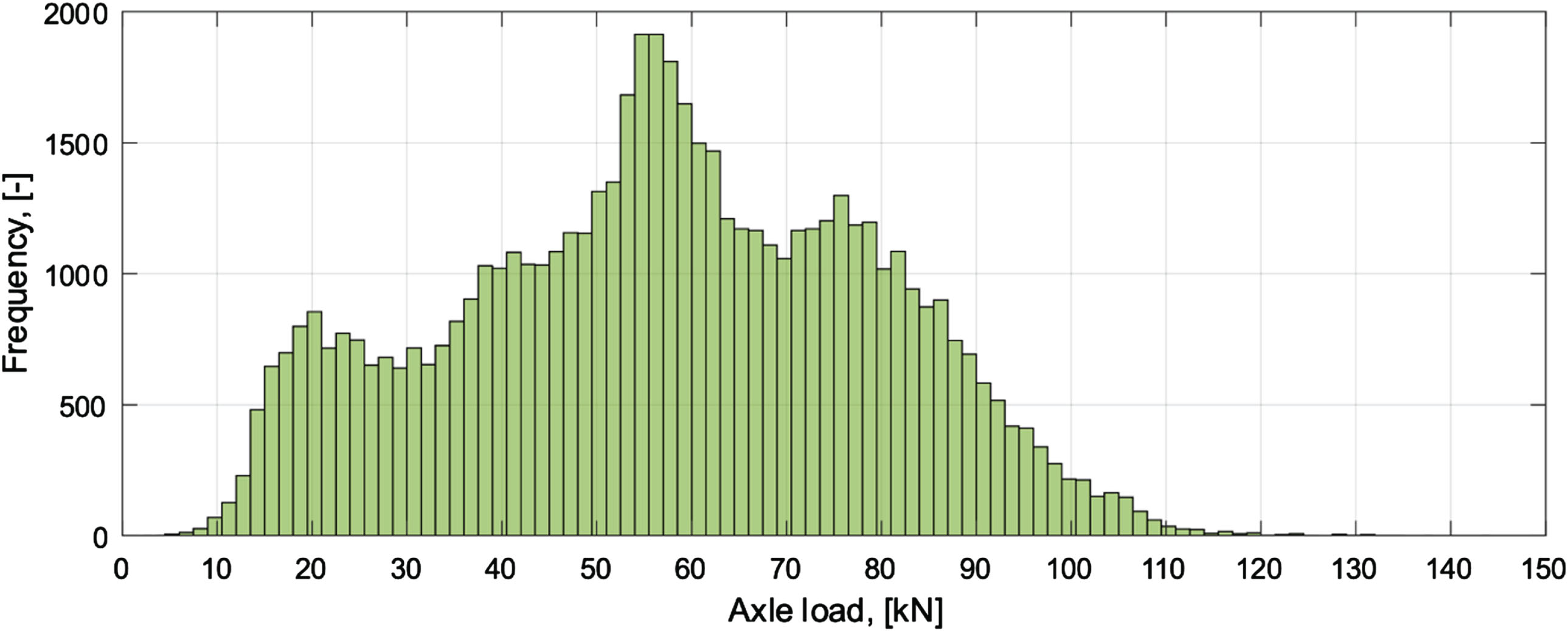
For bridges with short spans, it is more relevant to look at individual axles rather than vehicles crossing the bridge [31]. On one hand, due to the short span of many SSCBs, all the axles from longer heavy vehicles will not be located on the bridge simultaneously. On the other hand, when looking at the design of these structures, the most critical situation occurs when the heaviest axle loads are located at the center of the crown (which is the top of the pipe and also the point with the lowest cover height). Furthermore, every axle has the potential to stand close next to an axle from another vehicle, which might also represent a critical scenario for the design of SSCB. By looking at the number of vehicles and their corresponding number of axles, the number of axles in the different directions can be determined, as shown in Table 2. The distribution of axle loads for all the measured axles is presented in Fig. 6.
Table 2
Number of heavy vehicles and axles in both directions
| Number of axles for vehicles | Number of heavy vehicles towards “Kalmar” | Number of axles towards “Kalmar” | Number of heavy vehicles towards “Öland” | Number of axles towards “Öland” |
| 2 | 2 241 | 4 482 | 2 187 | 4 374 |
| 3 | 2 294 | 6 882 | 2 108 | 6 324 |
| 4 | 526 | 2 104 | 446 | 1 784 |
| 5 | 471 | 2 355 | 347 | 1 735 |
| 6 | 510 | 3 060 | 559 | 3 354 |
| 7 | 1 041 | 7 287 | 977 | 6 839 |
| 8 | 544 | 4 352 | 362 | 2 896 |
| 9 | 15 | 135 | 15 | 135 |
| 10 | 0 | 0 | 1 | 10 |
| Total | 7 642 | 30 657 | 7 002 | 27 451 |
Fig. 6
Distribution of axle loads for all the axles in the evaluation.
3Method
The study incorporates three different steps: (1) statistical extrapolation of measured loads, (2) finding the number of critical events to evaluate, and (3) performing Monte Carlo (MC) simulations for 1000-years to determine the characteristic values of the loads, which represents the same as the acceptable risk level in EC.
Considering that all of the mentioned steps are dependent on the yearly day traffic (YDT), a sensitivity analysis was performed where the results of four different YDT values were investigated.
3.1Statistical extrapolations
Due to the scarcity of traffic load measurements and their limited duration compared to the service life of a bridge, registering extreme loads occurring during its lifetime is highly unlikely. As such, load extrapolation is required in order to estimate the extreme load associated with a certain return period.
Rice formula is a common method for load extrapolation, which has been widely used by others in the past, see e.g. [26, 31–34]. The good performance of Rice formula has been highlighted in a recent study, [35], where a comparison between seven different methods was carried out. Rice formula was also found to provide robust results in the work done by [36] and was one of the methods used in the work with Eurocode according to [26, 37].
Rice formula, introduced in 1945 by Rice [38], can be used to find a parametric fit to a normally distributed stationary stochastic process. Since traffic loads can be generally assumed to follow a Gaussian distribution, Rice formula can be used to extrapolate traffic loads [32]. Rice formula counts the average number of times a stationary process exceeds a given threshold level, x > 0 during a reference period Tref as:
(1)
(2)
(3)
(4)
When all the parameters are determined through curve-fitting, the statistical extrapolation can be done analytically for a return period as:
(5)
(6)
As mentioned before, four different YDT values were considered to be able to find out how they could affect the results. However, it is worth mentioning that the heavy traffic on “Ölandsbron” is representative for the heavy traffic in the rest of Sweden [30] in terms of axle configurations and axle loads.
The first YDT value is taken from “Essingeleden” in Stockholm and corresponds to a YDT of 6060. The second value taken from the E4 highway close to Södertälje (southwest of Stockholm) features a YDT of 4040. The third value taken from the E20 highway at a position close to Brännebroa located 10 km North-East of Götene was chosen with a YDT of 2030. Finally, a value from E45 near Göta, located 53 km North of Gothenburg corresponds to a YDT value of 1530 [39]. The locations for the YDT of heavy vehicles were deliberately chosen to feature a difference of approximately 2000 heavy vehicles between the three places with highest YDT, and a narrower difference for the last location which is representative of the YDT on roads where these structures are most often used. So, for the YDT that was considered in this study, the corresponding Rt values are presented in Table 3.
Table 3
Rt values for the four different YDT
| YDT | Rt |
| 6060 | 2 211 900 000 |
| 4040 | 1 474 600 000 |
| 2030 | 740 950 000 |
| 1530 | 558 450 000 |
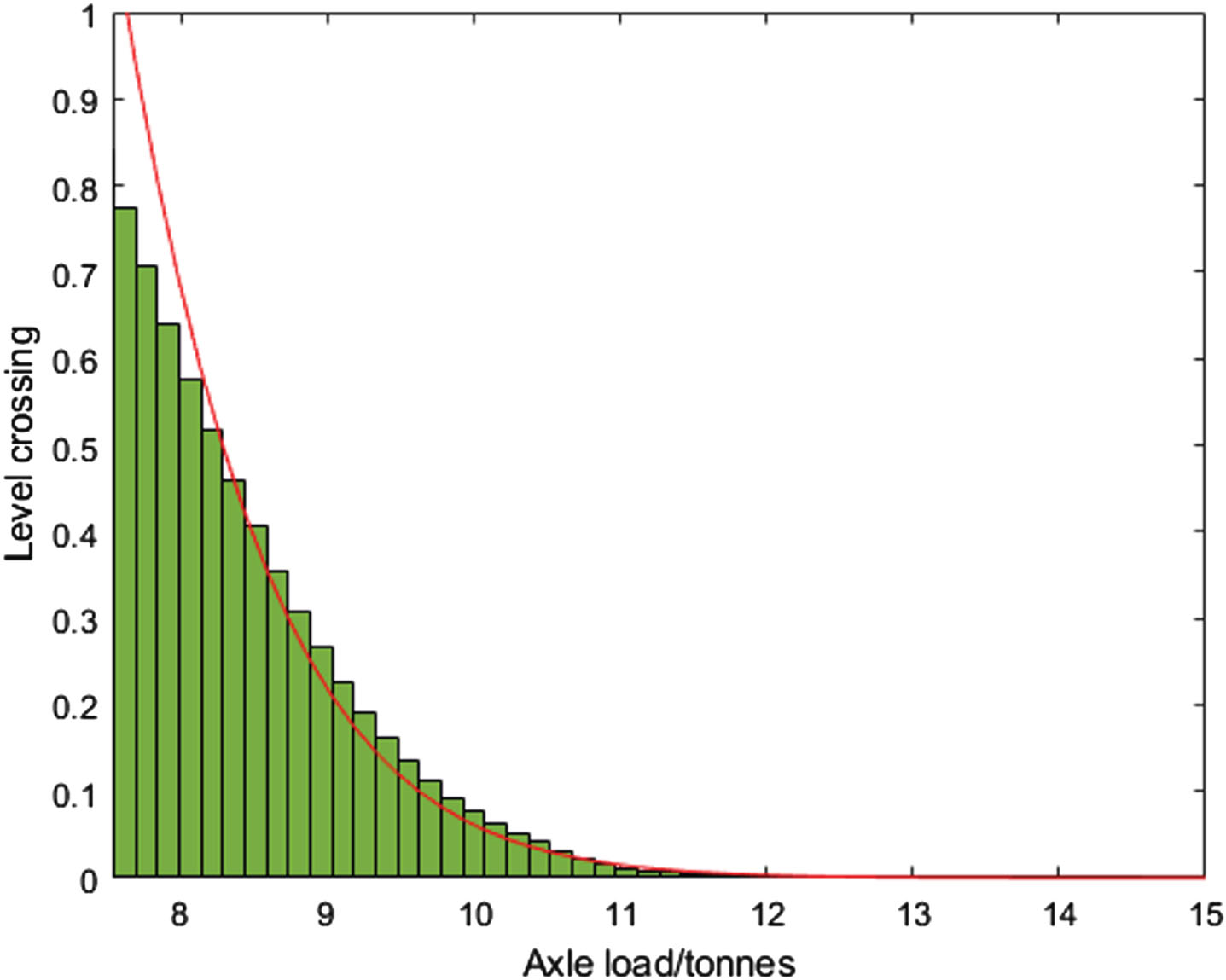
The curve fitting for the axle loads is shown in Fig. 7. The starting point and the bin width were chosen by performing the Kolmogorov test as suggested by [26], for a confidence level of 0.95. This resulted in a starting point at 7.6 ton and having 50 bins from the starting point.
Fig. 7
Curve-fitting for extrapolation with Rice-formula.
The extrapolation obtained by Equation (5) is presented in Fig. 8 as a function of the return period for the different YDT considered, whereas Table 4 shows the maximum value registered during the three measurement periods, the extrapolation for year one and year 1000, as well as the scale factor used for increasing the measured values in the rest of the analysis.
Fig. 8
Extrapolation of loads for a return period of 1000 years.
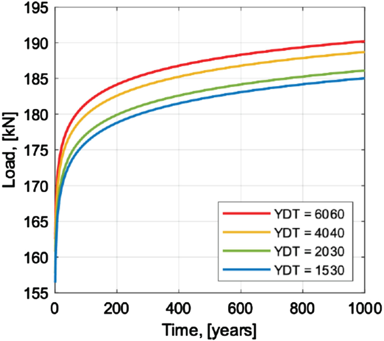
Table 4
Results from extrapolation
| YDT heavy vehicles | Maximum measured axle load [kN] | Extrapolated, one year return period [kN] | Extrapolated, 1000 years return period [kN] | Scale factor used for all the measured loads |
| 6060 | 143 | 163 | 190 | 1.332 |
| 4040 | 143 | 161 | 189 | 1.322 |
| 2030 | 143 | 158 | 186 | 1.304 |
| 1530 | 143 | 156 | 185 | 1.296 |
3.2Critical events
The critical events of interest in this study occur when two heavy vehicles are standing next to each other at the bridge. This situation may arise in two different ways, either if one heavy vehicle overtakes another heavy vehicle, or when two heavy vehicles are travelling in opposite directions and meet each other. The number of times any of these critical events arise depends on various factors, such as the influence length and the speed of the vehicles. The average span length of SSCB in Sweden is 4.28 m, where the critical part is often the crown (the top of the steel pipe). In this study, the influence length was considered as the distance between the quarter points of the average span length, resulting in an influence length of Linf = 2.14 m. To determine the number of critical events from a heavy vehicle passing another, the method applied in [30] was used. The velocity is chosen as the mean velocity in each direction, which gives the average time that a vehicle is within the critical part of the bridge as:
(7)
With the velocities of 71.2 km/h and 73.3 km/h for lane 1 and 2 respectively, gives that the average time there are vehicles in its respective lane is 0.108 s and 0.105 s.
The total time that there is a vehicle in each lane is then expressed as:
(8)
The probability that a vehicle is within the influence length in one traffic lane, however not at the same time are denoted P1 and P2, and they are expressed as:
(9)
With
(10)
Following Equations (7) – (10) for the four different YDT, with different intensity of heavy vehicles, the number of times each year that there are vehicles in both lanes is obtained.
The other possibility to get critical events is when two heavy vehicles meet each other. In the work done by [40], estimated number of meetings between heavy vehicles are compiled in a table (Table 7.3) for different traffic intensities (heavy vehicles), span length and velocities. This compilation is based on measurements performed at eight different places in Sweden during 2002 and 2003 where 278 122 vehicles were registered. Among these vehicles, 31 984 are classified as heavy vehicles. By implementing this table, it is possible to get the expected number of meetings for the influence length and the different YDT that we are interested in. The results from the number of expected critical events from the two possible situations and for the different YDT are presented in Table 5. It should be mentioned that the numbers given in Table 5 correspond to the number of meetings and overtakes by individual axles.
Table 5
Number of critical events from overtakes and from meetings between axles for different YDT
| YDT | Overtakes | Meetings |
| 6 060 | 65 939 | 80 703 |
| 4 040 | 29 306 | 35 850 |
| 2 020 | 7 399 | 8 951 |
| 1 530 | 4 203 | 5 131 |
From Table 5 it can be observed that meetings between two heavy vehicles generate more critical events than overtakes and is thereby the numbers that are used for the rest of this study.
There are other situations that could be critical, such as traffic jams and accidents near the bridge. However, since the critical events presented in Table 5 considers event from each individual axles, we mean that the chosen critical event is sufficient.
3.3Monte Carlo simulations
Monte Carlo simulations are commonly used for extreme traffic loading on bridges [25, 31, 41].
In the Monte Carlo simulations, axle loads come from the measurements that are described in section 3.1. At the location for the measurements, the road has four lanes, two in each direction. However, for simplicity, only two lanes are considered in the present study. All the heavy vehicles in their respective direction are thereby considered to be in one lane. This means that the total number of axles in one lane against “Kalmar” is 30 657. Having two lanes instead of four will generate more critical situations and is thereby considered to be acceptable.
The vehicles’ position in the lanes could be described by a normal distribution, as described in [30] and suggested in [20]. For the position in the lanes, it was assumed that vehicles drive with a centric position in the lane, with a standard deviation of 0.232 m, which was the most critical standard deviation observed in the two directions from the measurements performed in 2007 [30]. This observed value is almost the same as the standard deviation recommended in [20], where they recommend 0.24 m. The width of the lanes were assumed to be 3.0 m, which is the lane width in EC [24], and this is a bit narrower than what is suggested in [42], favoring the occurrence of critical situations.
The Monte Carlo simulation process was performed according to the following four steps, and is further described by Fig. 9 and Table 6:
Fig. 9
Simulation prerequisites.
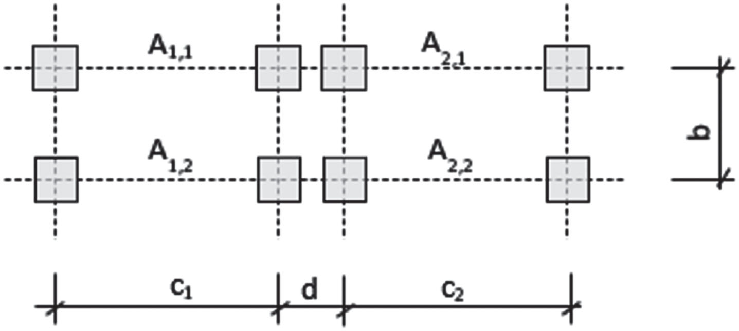
Table 6
Simulation prerequisites
| n cr | Number of critical events | Randomly drawn from a Poisson distribution described earlier |
| A1,1 = A1,2 | Axle load in lane 1 | Randomly drawn from the measurements |
| A2,1 = A2,2 | Axle load in lane 2 | Randomly drawn from the measurements |
| c1 = c2 | Distance between wheels | 2.0 m (same distance as for LM1) |
| b | Distance between axles | 1.2 m (same distance as for LM1) |
| d | Distance between vehicles | Randomly drawn from a normal distribution describes earlier |
1. The number of times that there is a critical situation, ncr, every year is randomly drawn from a Poisson distribution, with the mean value described earlier.
2. For every critical situation from 1, axle loads for lane 1 and lane 2 are randomly drawn from the measurements and increased with the scale factor given in Table 4. Each axle load is then used, as shown in Fig. 9.
3. The distance between the two vehicles, d, is randomly drawn from a normal distribution described earlier. If the distance between the center of the wheels for the two vehicles is < 0.30 m, two new positions are randomly drawn. The distance 0.30 m is considered as the width of the wheels, which is the same width as for “Typfordon” according to [29].
4. Point 1–3 is repeated 1000 times to represent 1000 year.
From the MC simulations, the number of critical situations evaluated was 80 698 693, 35 860 834, 8 945 073 and 5 127 313 for the different YDT, respectively. Since many situations will not be more critical than LM1, the resulting cases are filtered to reduce the number of evaluations. Three conditions were used to filter the number of critical situations to evaluate: (1) if the distance is > 0.65 m, (2) if one of the axle loads < 84 kN, (3) if the average load of the axles is < 137 kN. These filters were analytically tested to sort out the possible cases that could not be worse than LM1 in EC.
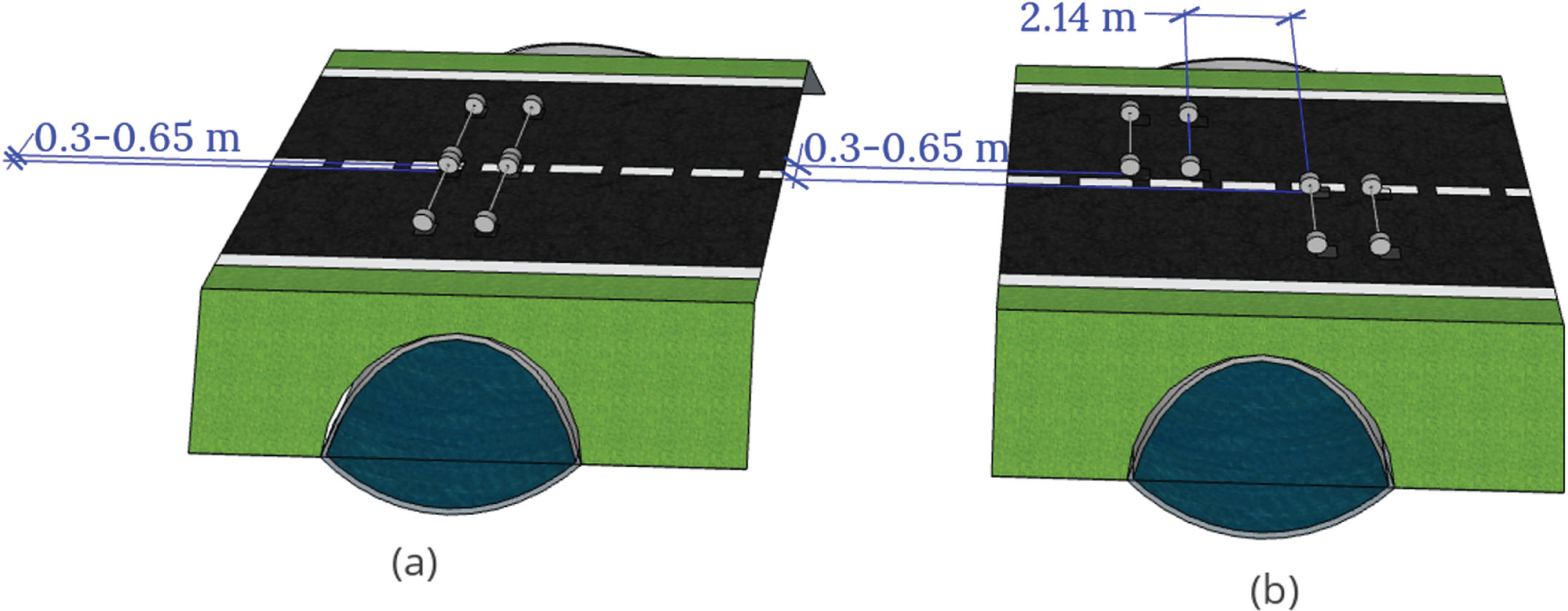
The two vehicles, with axles from the MC simulations and their corresponding distance, are driving over the bridge. Figure 10(a) represents that both vehicles are standing with one axle at the center of the crown. It is worth mentioning that for the analysis of the study, the vehicles are driving as shown in Fig. 10(a) for all the cases even though the vehicles could be placed anywhere in the influence length, which is shown in Fig. 10(b). When the vehicles are driving as shown in Fig. 10(b), there is more cover height since the vehicles are offset from the center of the crown. This is not taken into account with the applied position as shown in Fig. 10(a). It is important to mention that all axles that are received from the MC simulations are applied with the configuration as shown in Fig. 9 (same distance between axles and wheels as for LM1). For the contact area of the wheel, they have the same configuration as “Typfordon”, which is 0.2 m in the longitudinal direction and 0.3 m in the transverse direction [29]. The reason for choosing this contact area is that it better represent the contact area for a heavy vehicle, and it is also more conservative since it also allows the vehicles to stand even closer to each other compared to LM1.
Fig. 10
Position of the vehicle in the evaluation (a) and Possible positions of the vehicle after filter from MC simulations (b).
4Results and discussion
To find out if the load effect from the simulated critical cases is worse than the load effect from LM1, the equivalent line loads were compared. This was done for different cover heights and for different distances between the two vehicles in LM1. The equivalent line load can be calculated according to section 4.4.4 in [28] as:
(11)
Where hc,red is the reduced cover height and σV is calculated based on the summarized contribution of the point load from the wheels.
Table 7 shows the equivalent line load from LM1 at different cover heights and with different distances between the two vehicles, where 0.5 m corresponds to the case with local verification and 1.0 m corresponds to the normal case for LM1. The cover heights were chosen between 0.5 – 1.0 m. 0.5 m is the minimum allowed cover height according to [28] and after 1 m, the gap between local verification and the normal case for LM1 is decreasing, see Fig. 5. The axle loads are 270 kN and 180 kN in each lane respectively (αQiQik), with the adjustment factor 0.9 according to [29].
Table 7
Equivalent line load at the crown for different cover heights and different distances between the two vehicles in LM1, [kN/m]
| Cover height [m] | Equivalent line load [kN/m] | |||||
| Distance between the two vehicles in LM1 | ||||||
| 0.5 m | 0.6 m | 0.7 m | 0.8 m | 0.9 m | 1.0 m | |
| 0.5 | 196 | 183 | 176 | 172 | 169 | 168 |
| 0.6 | 188 | 174 | 165 | 159 | 156 | 154 |
| 0.7 | 180 | 167 | 157 | 150 | 146 | 143 |
| 0.8 | 173 | 162 | 152 | 144 | 139 | 135 |
| 0.9 | 167 | 158 | 149 | 141 | 135 | 130 |
| 1.0 | 163 | 155 | 147 | 139 | 133 | 128 |
What is of interest now is to compare the equivalent line loads from LM1 at different cover heights in Table 7, with the equivalent line loads from the critical cases from the MC simulations. The most critical cases from the MC simulations for the different YDT are presented in Table 8.
Table 8
Critical distances with associated axle loads for the different YDT
| YDT | Critical case | Distance [m] | Axle load 1 [kN] | Axle load 2 [kN] |
| 6060 | 1 | 0.31 | 150 | 190 |
| 4040 | 1 | 0.30 | 129 | 173 |
| 2 | 0.36 | 182 | 138 | |
| 3 | 0.42 | 169 | 164 | |
| 2030 | 1 | 0.33 | 136 | 171 |
| 1530 | 1 | 0.31 | 114 | 170 |
| 2 | 0.31 | 159 | 127 | |
| 3 | 0.38 | 129 | 170 | |
| 4 | 0.54 | 139 | 185 |
From Equation (11), the critical equivalent line loads from the MC simulations are presented in Table 9.
Table 9
Equivalent line load from the critical cases at different cover height for the different YDT, number in parenthesis is critical case from Table 7
| Cover height [m] | YDT 1530 Eq line load [kN/m] | YDT 2030 Eq line load [kN/m] | YDT 4040 Eq line load [kN/m] | YDT 6060 Eq line load [kN/m] |
| 0.5 | 166 (1) | 174 (1) | 177 (1) | 197 (1) |
| 0.6 | 150 (2) | 159 (1) | 161 (2) | 179 (1) |
| 0.7 | 138 (2) | 146 (1) | 149 (2) | 164 (1) |
| 0.8 | 128 (3) | 136 (1) | 139 (2) | 152 (1) |
| 0.9 | 121 (3) | 128 (1) | 132 (2) | 142 (1) |
| 1.0 | 117 (4) | 121 (1) | 127 (3) | 135 (1) |
Figure 11 shows the ratio between the critical equivalent line loads from the MC simulations and from LM1 at the different distances and cover heights (hc). A ratio below one indicates that the equivalent line load from LM1 is greater than that from the MC simulations. When the distance between LM1 approaches 1.0 m, the ratio also gets closer to 1.0, which means that the load effect from LM1 better represents the simulated extreme loads. It can also be observed that for the highest YDT, see Fig. 11(d) the MC simulations for the lowest cover height exceeds the equivalent line load from local verification from LM1 (0.5 m distance). It should be mentioned that the size of the wheels has a large impact on the design of SSCB. If the width of the wheels had been 0.3×0.3 m instead of 0.3×0.2, no loading case would exist that would not meet the requirements of local verification of LM1.
Fig. 11
Ratio of critical line load from MC simulation and different distances between LM1 at different cover heights (hc) for the different investigated YDT.
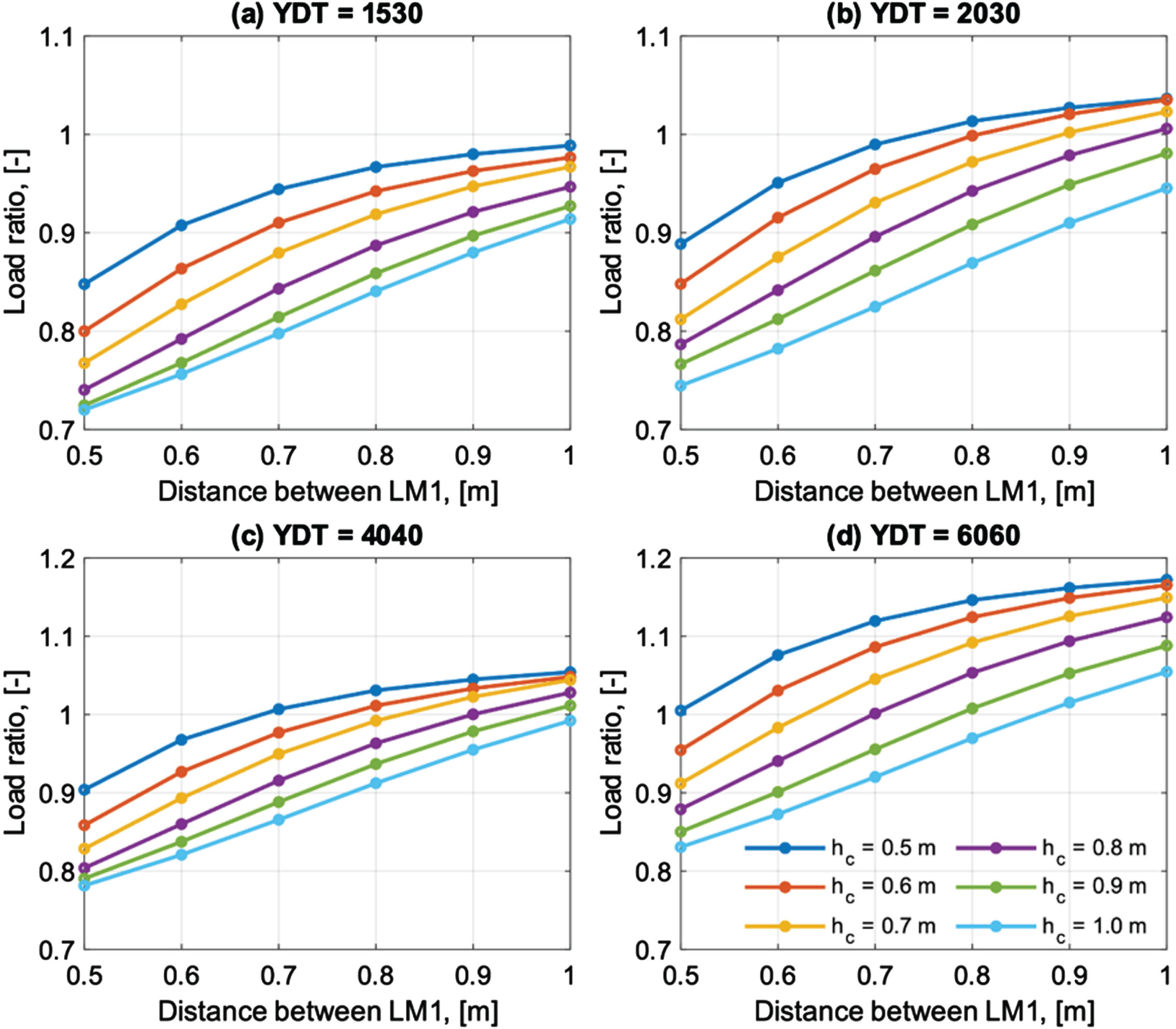
For the lowest YDT in this study, Fig. 11(a), there is no combination of distance and cover height that the ratio exceeds 1.0. This means that there is no case where the loads from the MC simulations exceed LM1.
From Fig. 11, it can be observed that a less restrictive implementation of local verification could be used for the design of SSCB without increasing the acceptable risk level in Eurocode, as long as the YDT is less than 6000. To design for loads that are closer to the acceptable risk level in EC, Table 10 presents recommendations for the implementation of local verification for the design of SSCB.
Table 10
Proposed distances between LM1 for local verification for design of SSCB at different height of cover and for different YDT from heavy vehicles
| Cover height | YDT≤1500 | 1500 < YDT≤2000 | 2000 < YDT≤4000 | 4000 < YDT≤6000 | YDT>6000* |
| 0.5 m < hc<0.6 m | 1.0 m | 0.7 m | 0.6 m | 0.5 m | 0.5 m |
| 0.6 m < hc<0.7 m | 1.0 m | 0.8 m | 0.7 m | 0.5 m | 0.5 m |
| 0.7 m < hc<0.8 m | 1.0 m | 0.8 m | 0.8 m | 0.6 m | 0.5 m |
| 0.8 m < hc<0.9 m | 1.0 m | 0.9 m | 0.8 m | 0.6 m | 0.5 m |
| 0.9 m < hc<1.0 m | 1.0 m | 1.0 m | 0.9 m | 0.7 m | 0.5 m |
| hc≥1.0 m | 1.0 m | 1.0 m | 1.0 m | 0.8 m | 0.5 m |
*Either used value or further investigation.
4.1Potential savings
The potential benefit from the results of this research is to reduce the amount of material that is used in SSCBs. In Sweden, SSCB are mostly built on roads where the YDT is in the lowest interval for this study. In the work done in [11], six different profiles, see Fig. 12, of SSCB are optimized using a Set-Based Design method. Each profile consists of several sizes within that particular shape.
Fig. 12
Studied profiles for potential savings.
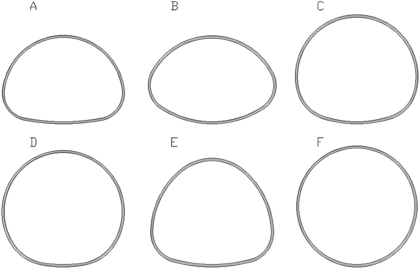
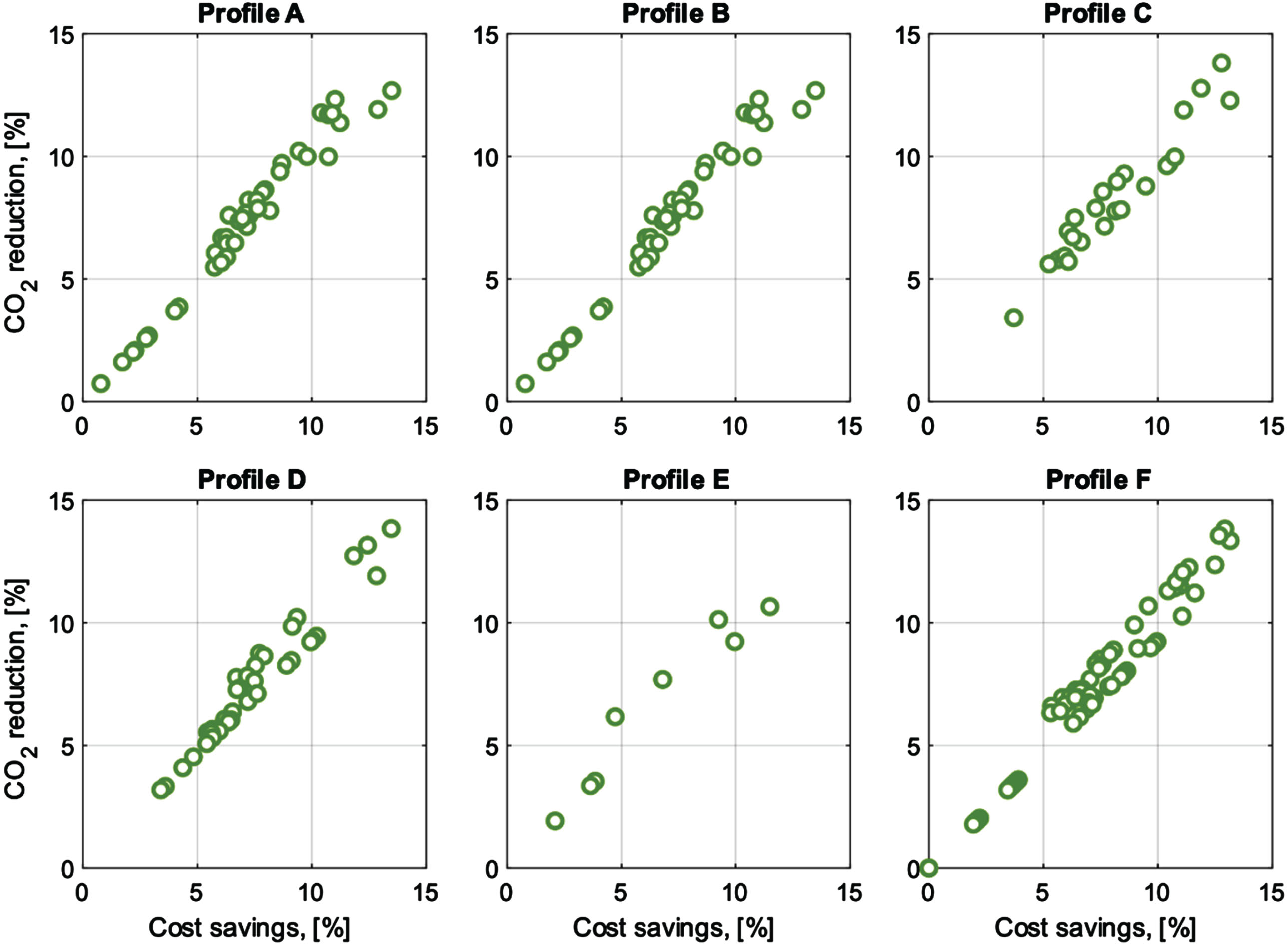
In this optimization, the optimal ratio between cover height, steel thickness and type of back-fill material is found. With the optimal ratio, the cost and CO2-equivalents are minimized. By implementing this Set-Based Design method together with the recommended distances for local verification given in Table 9, and with YDT (heavy vehicles) ≤1530, Fig. 13 shows that it is possible to save up to 14% in terms of economic cost and CO2-equivalents when designing SSCB. It is worth mentioning that the reductions shown in Fig. 13 are for SSCBs already optimized with respect to cover height and plate thickness. Profiles A–F are different profiles of the SSCBs and each marker represents different sizes of that particular shape. Note that when no reduction is possible, it means that LM1 was not originally the critical load case for this structure.
Fig. 13
Potential reduction in cost and CO2 if SSCB were designed without local verification of LM1.
5Conclusion
Soil-Steel Composite Bridges (SSCB) are Sweden’s most commonly built bridge type today. Optimizing the structure to decrease the amount of material, and thereby also the cost and environmental impact. As a complement to traditional optimization, this research has studied the probability of load case Local verification of Load Model 1 (LM1) in Euro Code, which is often the critical load case for the design of SSCBs. This load case was compared to weight in motion measurements from real traffic. The observed traffic load was extrapolated with Rice formula to represent a 1000-year value. Subsequently, using Monte Carlo (MC) simulations, the most critical cases were investigated for four different yearly day traffic scenarios, simulating the 1000-year event to obtain the same risk level as in Eurocode. The following conclusions can be drawn:
This study has shown that the requirements of local verification from LM1 could be relaxed without exceeding the acceptable risk level in Eurocode for YDT less than 6000. For higher YDT, values in Eurocode should be used or further investigations are needed.
A modification of the local verification requirements was proposed, which could lead to a reduction of the cost and CO2-equivalents of up to 14%. With the potential savings in cost and CO2-equivalents that have been shown, this could be an easy way to decrease the cost and climate impact for the most commonly built bridge in Sweden.
The results from this study could be implemented in other European countries for the design on SSCB, provided the regulations in other countries do not allow for higher axle loads than in Sweden, and that the adjustment factor for LM1 αi≥0.9, and that the number of critical events is equal to or less than the ones used in this study.
The measurements were limited to three weeks as previous studies have indicated that three weeks is a sufficiently long period [26]. Even though measurements could be extended, it seems unlikely that the length of the measurements would have a major impact on the overall results. The fact the measurements were performed during 2020, which is Covid year, could have some impact on the results. However, since the YDT are increased compared to the measured ones and the extrapolation of the loads, we believe that the results from this study are valid. The size of the wheels have significant impact on the design of SSCB, which has been shown in [28]. If the analysis had been performed with the same wheel-size as for LM1, the observed ratio would have decreased even more. The assumed influence length could be considered as conservative because it does not take increased cover height into account when the vehicles are placed offset from the center of the crown. The assumed distance between the vehicles could be considered as conservative since it assumes that the vehicles are standing next to each other so there is contact between the wheels, which would mean that the two vehicles have collided.
Acknowledgments
A special thanks to the Swedish Transport Administration and to the company Broleri for sharing the data from the measurements performed during 2020, which was used in this study. Finally, a special thanks to Associate Professor John Leander at KTH for valuable discussions and support with Rice Formula.
Funding
This study is part of an Industrial PhD project, financed by the Swedish Transport Administration, grant number TRV 2020/65121.
Conflict of interest
The authors have no conflict of interest to report.
Author contributions
Johan Lagerkvist: Conceptualization, Methodology, Validation, Writing – original draft preparation, Writing – reviewing and editing. Carlos Gil Berrocal: Conceptualization, Methodology, Validation, Writing – reviewing and editing. Fredrik Carlsson: Conceptualization, Methodology, Validation, Writing – reviewing and editing. Rasmus Rempling: Writing – reviewing and editing, Supervision, Project administration.
All authors have had access to the data.
All authors have read and agreed to the published version of the manuscript.
References
[1] | Miljömålsberedningen. SOU. 2016:21, Ett klimatpolitiskt ramverk för Sverige, https://www.regeringen.se/rattsliga-dokument/statens-offentliga-utredningar//03/sou-21/ ((2016) , accessed 4 November 2021). |
[2] | Trafikverket. TDOK 2015:0480, , Klimatkrav i planläggning byggskede underhåll och på teknisk godkänt järnvägsmateriel. (2021) . |
[3] | BaTMan Extern Portal, https://batman.trafikverket.se/externportal (accessed 3 November 2021). |
[4] | Wadi A , Pettersson L , Karoumi R . On Predicting the Ultimate Capacity of a Large-Span Soil–Steel Composite Bridge. Int J Geosynth Gr Eng. (2020) ;6: :1–13. |
[5] | Du G , Pettersson L , Karoumi R . Soil-steel composite bridge: An alternative design solution for short spans considering LCA. J Clean Prod. (2018) ;189: :647–61. |
[6] | Ek K , Mathern A , Rempling R , et al. Life cycle sustainability performance assessment method for comparison of civil engineering works design concepts: Case study of a bridge. Int J Environ Res Public Health. (2020) ;17: :1–34. |
[7] | Yavari MS , Du G , Pacoste C , et al. Environmental Impact Optimization of Reinforced Concrete Slab Frame Bridges. J Civ Eng Archit; 10. Epub ahead of print (2016) . DOI: 10.17265/1934-7359/2016.04.001. |
[8] | Majid Solat Yavari , Costin Pacoste , Raid Karoumi . Structural Optimization of Concrete Slab Frame Bridges Considering Investment Cost. J Civ Eng Archit; 10. Epub ahead of print (2016) . DOI: 10.17265/1934-7359/2016.09.002. |
[9] | Rempling R , Mathern A , Tarazona Ramos D , et al. Automatic structural design by a set-based parametric design method. Autom Constr. (2019) ;108: :102936. |
[10] | García-Segura T , Yepes V . Multiobjective optimization of post-tensioned concrete box-girder road bridges considering cost, CO2 emissions, and safety. Eng Struct. (2016) ;125: :325–36. |
[11] | Lagerkvist J , Berrocal CG , Rempling R . Climate-smarter design of Soil-Steel Composite Bridges using Set-Based Design. In: Zingoni A (ed) Current Perspectives and New Directions in Mechanics, Modelling and Design of Structural Systems. Cape Town: CRC Press/Balkema, Taylor & Francis Group, (2022) , pp. 2001–2006. |
[12] | Solat Yavari M . Slab Frame Bridges – Structural Optimization Considering Investment Cost and Environmental Impacts. KTH Royal Institute of Technology, (2017) . |
[13] | Yavari MS , Pacoste C , Karoumi R . Structural optimization of concrete slab frame bridges using heuristic algorithms. OPT-i 2014 – 1st Int Conf Eng Appl Sci Optim Proc. (2014) :140–6. |
[14] | Mathern A , Steinholtz OS , Sjöberg A , et al. Multi-objective constrained Bayesian optimization for structural design. Struct Multidiscip Optim. Epub ahead of print (2020) . DOI: 10.1007/s00158-020-02720-2. |
[15] | Carbonell A , González-Vidosa F , Yepes V . Design of reinforced concrete road vaults by heuristic optimization. Adv Eng Softw. (2011) ;42: :151–9. |
[16] | Rezaei A , Derakhshani A . Optimization of the design of soil-steel high profile arch using particle swarm optimization. In: 12 th International Congress on Civil Engineering. (2021) , pp. 1–7. |
[17] | Kazakis G , Kanellopoulos I , Sotiropoulos S , et al. Topology optimization aided structural design: Interpretation, computational aspects and 3D printing. Heliyon. (2017) ;3: :e00431. |
[18] | Briseghella B , Fenu L , Lan C , et al. Application of Topological Optimization to Bridge Design. J Bridg Eng. (2013) ;18: :790–800. |
[19] | Sobótka M . Shape optimization of flexible soil-steel culverts taking non-stationary loads into account. Structures. (2020) ;23: :612–20. |
[20] | O’Connor A , Enevoldsen I . Probability-based assessment of highway bridges according to the new Danish guideline. Struct Infrastruct Eng. (2009) ;5: :157–68. |
[21] | Bailey SF , Bez R . Site specific probability distribution of extreme traffic action effects. Probabilistic Eng Mech. (1999) ;14: :19–26. |
[22] | Markova J , Holicky M , Sykora M , et al. Probabilistic assessment of traffic loads on bridges. In: Safety, Reliability and Risk Analysis: Beyond the Horizon – Proceedings of the European Safety and Reliability Conference, ESREL 2013. (2014) , pp. 2613–8. |
[23] | Trafikverket. TRVINFRA-00226 Brobyggnad Bro och broliknande konstruktion, Allmänna krav Trafikverkets infrastrukturregelverk. (2020) . |
[24] | CEN. Eurocode 1: Actions on structures – Part 2: Traffic loads on bridges (EN 1991-2). Brussels, (2003) . |
[25] | Enright B , O’Brien EJ . Monte Carlo simulation of extreme traffic loading on short and medium span bridges. Struct Infrastruct Eng. (2013) ;9: :1267–82. |
[26] | Cremona C . Optimal extrapolation of traffic load effects. Struct Saf. (2001) ;23: :31–46. |
[27] | O’brien EJ , Caprani CC , O’connell GJ . Bridge assessment loading: A comparison of West and Central/East Europe. Bridg Struct. (2006) ;2: :25–33. |
[28] | Pettersson L , Sundquist H . Design of soil steel composite bridges, Report 112, 5th Edition, www.byv.kth.se ((2014) , accessed 30 October 2021). |
[29] | Transportsyrelsen. TSFS 2018:57 -Transportstyrelsens föreskrifter och allmänna råd om tillämpning av eurokoder, https://www.transportstyrelsen.se/TSFS/TSFS2018_57.pdf ((2018) ). |
[30] | Carlsson F , Karoumi R . Probabilistisk analys av Ölandsbron baserad på fordonens verkliga laster och sidopositioner. (2008) . |
[31] | O’connor A , O’brien EJ . Traffic load modelling and factors influencing the accuracy of predicted extremes. Can J Civ Eng. (2005) ;32: :270–8. |
[32] | Lu N , Ma Y . Evaluating Probabilistic Traffic Load Effects on Large Bridges Using Long-Term Traffic Monitoring Data. Sensors. (2019) ;19: :1–16. |
[33] | Chen W , Ma C , Xie Z , et al. Improvement of extrapolation of traffic load effect on highway bridges based on Rice’s theory. Int J Steel Struct. (2015) ;15: :527–39. |
[34] | Flint AR , Jacob B . Extreme traffic loads on road bridges and target values of their effects for code calibration. In: IABSE REPORTS. (1996) , pp. 469–78. |
[35] | OBrien EJ , Schmidt F , Hajializadeh D , et al. A review of probabilistic methods of assessment of load effects in bridges. Struct Saf. (2015) ;53: :44–56. |
[36] | Nowak M , Straub D , Fischer O . Statistical Extrapolation for Extreme Traffic Load Effect Estimation on Bridges. In: Caspeele R,Luc T,Proske D (eds) 14th International Probabilistic Workshop. Springer, (2017) , pp. 135–53. |
[37] | Zhou XY , Schmidt F , Jacob B . Extrapolation of traffic data for development of traffic load models: assessment of methods used during background works of Eurocode. In: IABMAS2012, 6th Conference on Bridge Maintenance, Safety and Management, https://hal.archives-ouvertes.fr/hal-01213632 ((2012) ). |
[38] | Rice SO . Mathematical Analysis of Random Noise. Bell Syst Tech J. (1945) ;24: :46–156. |
[39] | Trafikverket. Vägtrafikflödeskartan, https://vtf.trafikverket.se/SeTrafikinformation (accessed 3 June 2022). |
[40] | Carlsson F . Modelling of Traffic Loads on Bridges Based on Measurements of Real Traffic Loads in Sweden. Structural Engineering, Lund University, http://lup.lub.lu.se/record/25826 ((2006) , accessed 25 September 2022). |
[41] | Liang Y , Xiong F . Multi-parameter Dynamic Traffic Flow Simulation and Vehicle Load Effect Analysis based on Probability and Random Theory. KSCE J Civ Eng. (2019) ;23: (8):3581–91. |
[42] | VGU Vägars och gators utformning. |

![Definition of Load Model 1 (a) and Load Model 2 (b) according to the Eurocode [24].](https://content.iospress.com:443/media/brs/2024/20-3-4/brs-20-3-4-brs240228/brs-20-brs240228-g003.jpg)
![Illustration of the load case for local verification of Load Model 1 according to EC [24].](https://content.iospress.com:443/media/brs/2024/20-3-4/brs-20-3-4-brs240228/brs-20-brs240228-g004.jpg)


