
Structural analysis of a rehabilitative training system based on a ceiling rail for safety of hemiplegia patients
Abstract
The body-weight support (BWS) function, which helps to decrease load stresses on a user, is an effective tool for gait and balance rehabilitation training for elderly people with weakened lower-extremity muscular strength, hemiplegic patients, etc. This study conducts structural analysis to secure user safety in order to develop a rail-type gait and balance rehabilitation training system (RRTS). The RRTS comprises a rail, trolley, and brain-machine interface. The rail (platform) is connected to the ceiling structure, bearing the loads of the RRTS and of the user and allowing locomobility. The trolley consists of a smart drive unit (SDU) that assists the user with forward and backward mobility and a body-weight support (BWS) unit that helps the user to control his/her body-weight load, depending on the severity of his/her hemiplegia. The brain-machine interface estimates and measures on a real-time basis the body-weight (load) of the user and the intended direction of his/her movement. Considering the weight of the system and the user, the mechanical safety performance of the system frame under an applied 250-kg static load is verified through structural analysis using ABAQUS (6.14-3) software. The maximum stresses applied on the rail and trolley under the given gravity load of 250 kg, respectively, are 18.52 MPa and 48.44 MPa. The respective safety factors are computed to be 7.83 and 5.26, confirming the RRTS’s mechanical safety. An RRTS with verified structural safety could be utilized for gait movement and balance rehabilitation and training for patients with hemiplegia.
1.Introduction
Gait refers to ambulatory movements that involve locomotion from one place to another, which involves maneuvering of various joints and the hip and continuous movement of muscles for propelling the body’s center of gravity forward [1]. Hence, gait is one of the most fundamental human body movements for executing daily activities. Owing to the changing social structure and the resulting aging of societies, the elderly population with weaker lower-extremity musculature and musculoskeletal systems is growing while the number of people with disabilities owing to various accidents and other factors is increasing. The majority of the foregoing populations experience difficulties with gait. Locomobility challenges limit the social engagement of the elderly and disabled, thus leading to a falling index of quality of life in these populations despite quality of life being essential for them [2].
The body weight support system (BWS) that allows a patient to support his or her body weight in step-wise fashion, depending on their physical condition, is an important intervention that assists individuals with gait disabilities in their gait rehabilitation. The literature reports that Visintin applied a new gait training method to stroke patients using BWS and treadmill simulations [3], while Hesse investigated the effects of partial BWS as well as treadmill gait training in hemiplegic patients [4, 5]. Working with patients with Parkinson’s disease, Miyai studied the effects of BWS along with treadmill training [6]. Werner compared the effects of a treadmill gait training scheme for subacute stroke patients that incorporated gait training equipment and BWS [7]. Of note, treadmill gait training involves gait movements to be executed on a motorized treadmill where the position of the trainee is fixed within a designated space and achieving natural gait movements is difficult. In that sense, treadmill gait differs greatly from over-ground gait. Numerous studies have compared kinematic factors to verify differences in joint angle between treadmill and over-ground gaits, kinetic factors to verify differences in forces (joint torque, etc.), and other related factors [8, 9, 10]. Of particular note, a number of studies have targeted patients with stroke or incomplete spinal cord injuries, comparing the effects of BWS-based treadmill gait training and over-ground gait training [11, 12, 13].
Hidler developed a ceiling-rail-based, zero-G, over-ground gait and balance rehabilitation training system [14]. The developed system is currently subject to various research efforts in clinics in the U.S. which target metabolism, muscle use patterns, etc. in patients with stroke-induced hemiplegia or incomplete spinal cord injuries [15, 16]. The developed system, however, is connected to a power cable in order to allow motor operation, and thus suffers limitations in space use. For problem solving, Kim conducted basic research on the design of a cable-free, battery-operated, on-rail over-ground gait training system [17, 18, 19]. The use of a battery, however, limited the maximum allowable dynamic load (weight support) to 68 kg.
This study aims to design a gait and balance rehabilitation training system using a rail platform connected to a power cable in order to allow extended range of locomobility, including indoor hallways. Furthermore, the study aims to examine the verification of mechanical safety of the system under a static gravity load of 250 kg.
2.System setup
2.1Overview of the rail-type rehabilitation training system
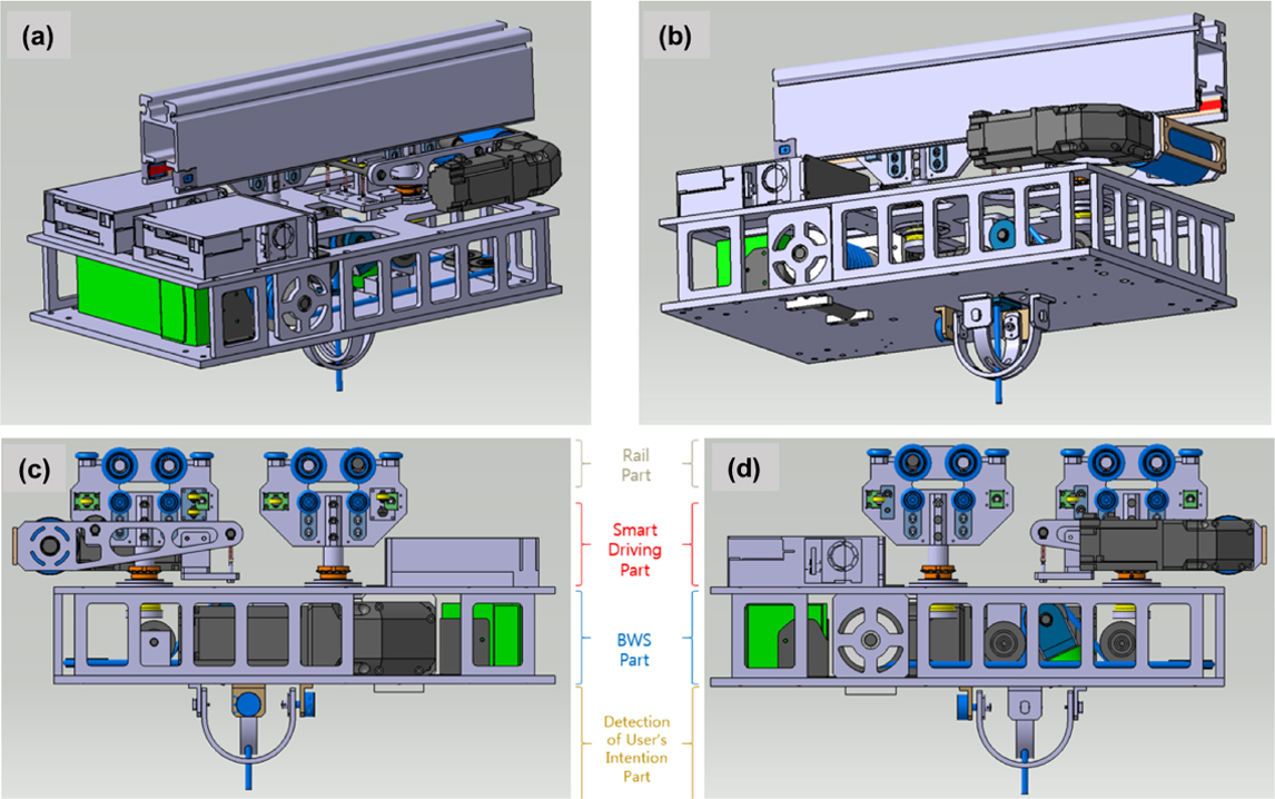
The rail-type rehabilitation training system (hereinafter the RRTS) is a gait and balance training system using rails that are installed into the ceiling structure. As shown in Fig. 1, the RRTS consists of a rail unit to be installed into the indoor ceiling structure; a trolley unit that offers an automated smart drive and body weight support (BWS) for rehabilitation training; and a harness unit to be worn by the patient. Specifically, the RRTS includes smart driving which assists the patient with his/her forward and backward driving; the BWS is connected via cord to a harness worn by the patient for controlling BWS steps; and a brain-machine interface that measures and estimates the direction of the user’s movement/ locomobility and measures real-time weight information. Figure 1a and b shows a drawing of an RRTS design that offers smart driving and BWS functionality. The gait rehabilitation system has dimensions of 565 mm (length)
Figure 1.
Design of the gait rehabilitation system.
2.2Tunnel-type rail design
As shown in Fig. 1, the tunnel design allows the drive rollers to be positioned on the rail. As a portion of the rail is inserted into the ceiling structure, the smart driving unit connected to the rail is fixed directly onto the surface of the ceiling. This configuration allows for easy installation even onto a low ceiling. The mentioned rail design is complete, and takes into consideration frame removal and bending manufacture needed for the bent section as well as the subsequent mass production of the developed design. Furthermore, curve drive simulations were performed to ensure smooth driving not only in the linear driving section but in the curved driving section, as well. The radius of curvature of the designed rail was established at between 720 and 1,000 mm to ensure that the radius of curvature can be accommodated by narrow hallways found in clinical institutions.
2.3Design of the smart driving unit
The smart driving unit (hereinafter the SDU) is capable of forward and backward maneuvering movements from the rail and is composed of (a) the main driving part, including the main roller connected to the driving motor and (b) the assistive driving part that supports manual driving according to the operation of the main driving unit.
The main roller connected to the main driving unit motor is designed such that the gap between the underside of the rail and the main driving unit is adjusted by a tension coil spring to ensure consistent contact between the underside and the unit. The main driving part and the assistive driving part each have four linear-driving rollers and four curve-driving rotary guide rollers; hence, together there are in total 16 rollers. The selected linear driving rollers are able to withstand a load of 35 kg in the direction of gravity whereas the selected rotary guide rollers can each endure 8 kg of loading in the horizontal direction. In other words, a 280 kg load in the direction of gravity and a 64 kg horizontal load can be withstood by the design. The dimensions took into consideration the weight of the entire system to be applied onto the tunnel-type rail and that of the patient.
As illustrated in Fig. 1c and d, the connection between the smart drive part and the BWS adopts a rotation connector configuration composed of ball bearings (to secure against vibration, etc.) and thrust bearings (to ensure smooth curved driving of the SDU) in order to ensure a rotary connection to the main and assistive driving parts.
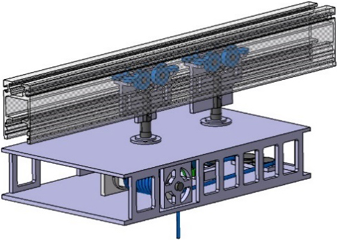
Figure 2.
Simplified model apparatus of the rail and the driving part.
2.4BWS unit design
The design of the RRTS ensures the security of left-right as well as front-rear balance by minimizing the total weight of the RRTS and placing the key parts on both sides. The BWS consists of the BWS motor and the brain-machine interface. The former is connected to the winch drum and allows the mitigation of body-weight loading through vertical movement of the harness worn by the user. The latter is capable of estimating the direction of intended movement of the user and measuring his/her weight on a real-time basis. The wires to be wound around the winch drum are connected to the four rollers, which are in turn connected to the harness to be worn by the user. The BWS motor can lift a maximum load of 360 kg using a 40:1 gear ratio.
3.Method of structural analysis
3.1Simplified model of the RRTS
The tunnel-type rail design utilizes a light-weight rail configuration to ensure mass production of the design, and forms a 1-m-long rail model. This study investigated a structure capable of withstanding a support load of 250 kg considering the SDU connected to the rail, the trolley including the BWS, and the weight of the user. As shown in Fig. 2, a simplified version of the model was constructed for structural analysis. In this simplified model, linear hexahedral elements of type and quadratic tetrahedral elements of type were used, and total number of nodes and elements are 899,191 and 660,879, respectively. Furthermore, safety factors were computed for the rail unit that statically supports trolley and user body weight and with emphasis on the trolley frame that supports the load of the user only.
Table 1
Material properties of the driving part
| Property | SUS304 | S45C | AL6063 | AL5052 |
|---|---|---|---|---|
| Young’s modulus, | 193 GPa | 205 GPa | 68.9 GPa | 70.3 GPa |
| Poisson’s ratio, | 0.29 | 0.29 | 0.33 | 0.33 |
| Density, | 8,000 kg/m | 7,850 kg/m | 2,700 kg/m | 2,680 kg/m |
| Yield strength, | 215 MPa | 343 MPa | 145 MPa | 255 MPa |
| Tensile strength, | 505 MPa | 569 MPa | 186 MPa | 290 MPa |
3.2Material properties
The materials adopted for the unit frame and rollers utilized for the simplified modeling of the SDU were stainless steels (S45C, SUS304) while the materials used for the remaining components (including the rail) are aluminum alloys (AL6063, AL50502). Table 1 summarizes the applied properties of these materials.
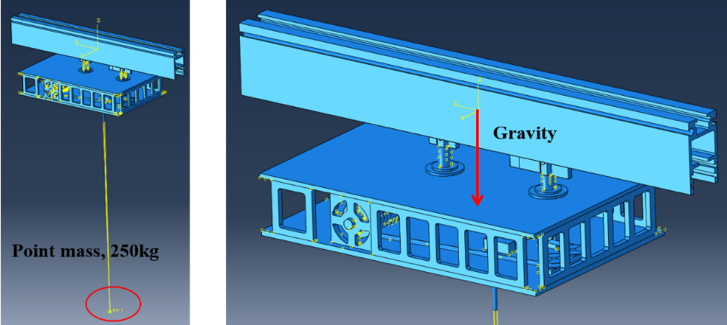
Figure 3.
Load conditions for the driving part.
3.3Conditions for structural analysis
The load conditions applied to structural analysis of the RRTS included gravitational acceleration, which was implemented to apply self-weight owing to the effects of gravity. Furthermore, for increased analysis efficiency, a total of 250 kg of loads (hypothesizing 50 kg for the SDU system weight and a maximal value of 200 kg for the user body weight) were simplified using the point mass, as shown in Fig. 3, with weighting implemented.
Figure 4 illustrates the boundary conditions: the region where the rail was inserted into the ceiling structure was fixed by the guide connector on each side of the top of the rail.
4.Results of structural analysis
4.1Structural analysis results for SDU
A 250 kg gravity support load was applied for analysis taking into consideration the total load of the RRTS and the maximum load of the user.
Figure 5 shows the results of the deflection of the system brought on by the applied loading conditions. The results showed no change in the deflection of the underside of the rail. As the maximum deflection analyzed was 1.88 mm, it was ruled that there was no distortion in the unit for a 250-kg load.
Table 2
Results of structural analysis in the driving part
| Item | Result | Safety factor | |
|---|---|---|---|
| Deflection (mm) | 1.88 | – | |
| Max. stress (MPa) | Rail | 18.52 | 7.83 |
| Roller for driving | 150.0 | 1.43 | |
| Assistive driving | 48.44 | 5.26 | |
Figure 4.
Boundary conditions of the driving part.
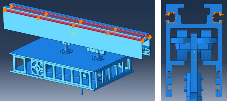
Figure 5.
Deflection results for the rehabilitation training system.
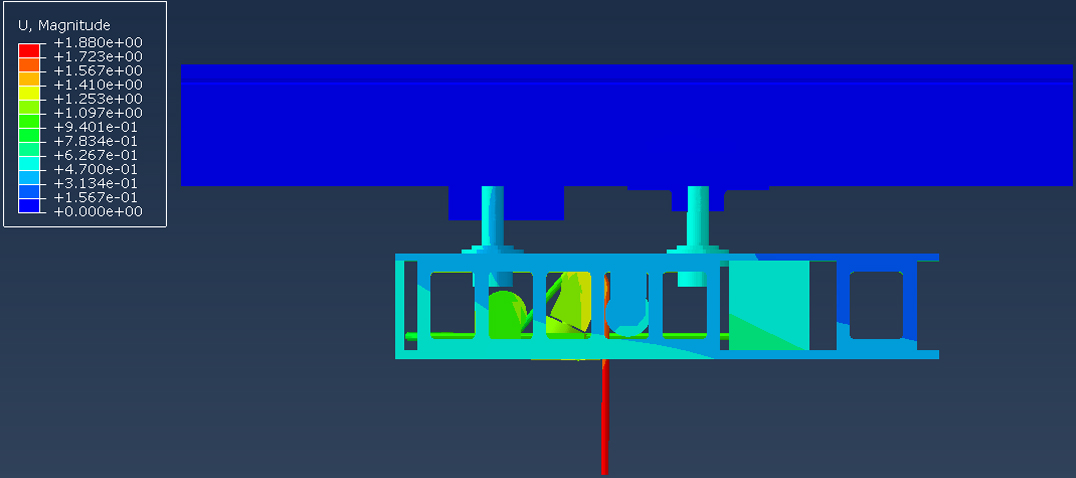
Figure 6.
Results of stress contours in the rail part.
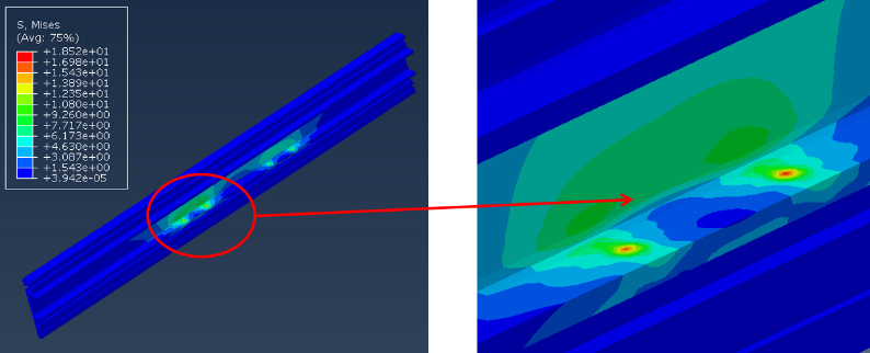
Figure 7.
Results of stress contours in the smart driving part.
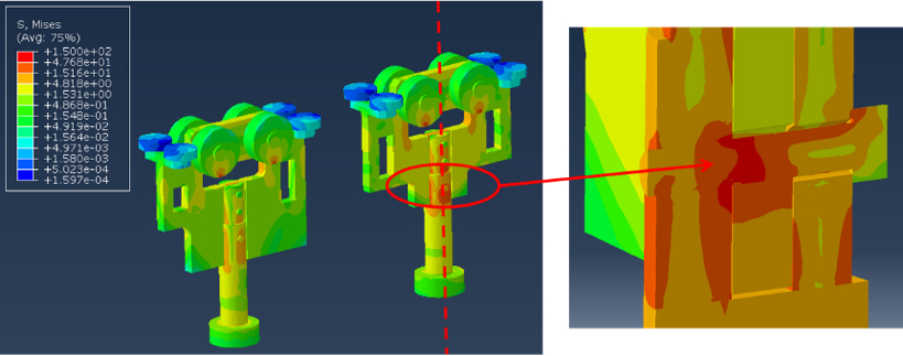
Figures 6 and 7 illustrate the results of stress analysis on the rail and the driving part. When a 250-kg support load was applied in the direction of gravity, the majority of the stresses on the rail were found to have been applied to the main/assistive roller connector of the SDU (Fig. 5). The maximum stress applied to the underside of the rail was calculated to be 18.52 MPa. The mechanical safety factor was computed using Eq. (1) while the safety factor for the rail was calculated to be 7.83. The stress distributions of the SDU’s main and assistive drive parts were obtained as shown in Fig. 7. The maximum stress and the safety factor on the axis of the main drive part were calculated to be 150 MPa and 1.43, respectively.
Figure 8.
Result of deflection contours in the plate of the BWS.
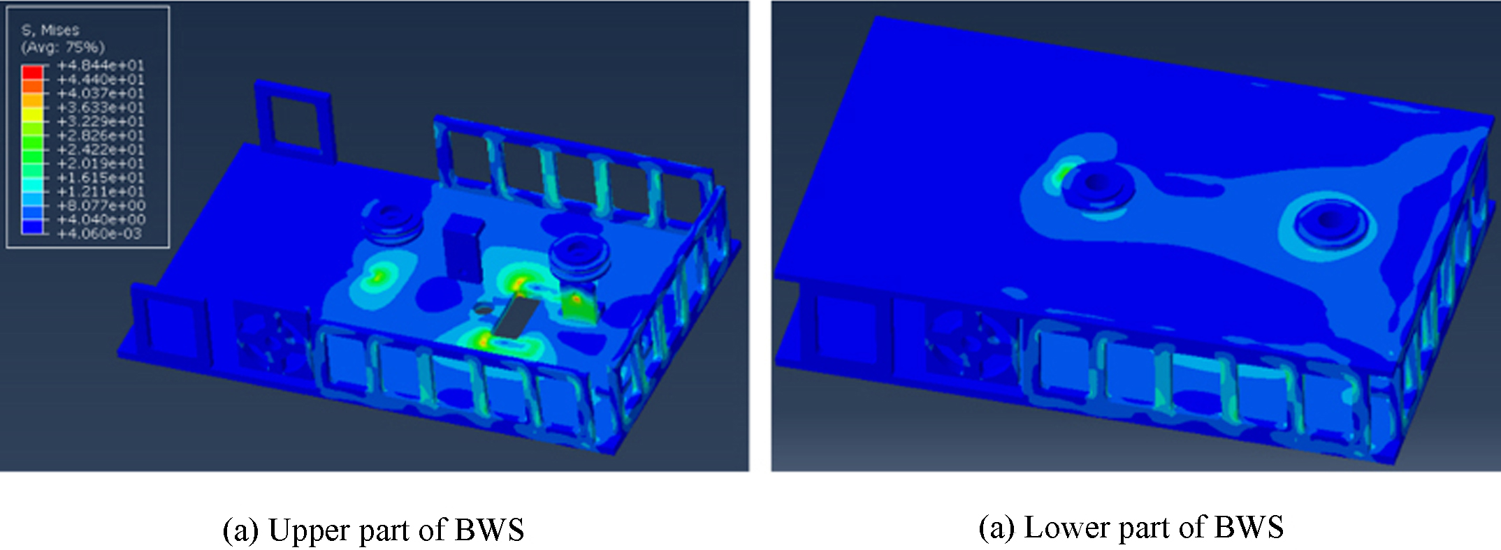
When a load of 250 kg was applied through the wires of the BWS in the direction of gravity, the concentration of stresses was confirmed to occur in the lower plate of the BWS, with the last roller that connects to the winch drum (Fig. 8) as the focal point. The maximum stress value for the BWS was estimated to be 48.44 MPa, and the calculated safety factor for the allowable strength criterion was 5.26. The foregoing results were understood to indicate that, even when the maximum allowable load of the user was applied, the trolley could still fully support the unit.
Figure 9.
Apparatus of the first prototype of the gait rehabilitation system.
Considering the load of the RRTS and the maximum load of the user, Table 2 summarizes the safety factors (yield strength/max. stress values, Eq. (1)) based on the maximum stress load of each section of the system and those based on the allowed strengths of the parts where the maximum stress was applied. Since all of the calculated safety factors were found to be greater than 1, ranging between 1.43 and 7.83, the system’s integrity is believed to have been secured.
(1)
5.Discussion
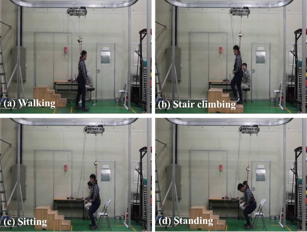
The body-weight support function, which helps to decrease load stresses on a user, is important to people with gait disorder. The rehabilitative training system based on a ceiling rail for weight supporting of hemiplegia patients was designed and the mechanical safety performance of this system frame under an applied 250-kg static load is verified through structural analysis in this system. Based on the results of structural simulations performed on the rail and on the trolley (SDU and BWS), the system’s integrity was judged to have been secured even when a maximum of 250 kg of loading was applied in the direction of gravity. Based on this assessment, the system was constructed (Fig. 9) and tested for users. Figure 9 shows a user who was a healthy adult weighing 85 kg wearing the harness in dynamic motion, that is, walking, stair climbing, sit-to-stand and stand-to-sit motion. With up to 30–50% of his load (body weight) supported by the system, the user was instructed to walk, ascend and descend steps, sit, and stand. As shown, the safety of the RRTS was verified during the actual movement tests conducted by the user.
6.Conclusion
This study designed a rail-type rehabilitation training system (RRTS) for hemiplegic patients in order to offer them gait and balance rehabilitation training. Static safety performance was examined for the rail unit and the trolley (including the smart drive part or SDU and the body-weight support or BWS) of the system. Considering the respective weights of the RRTS and the user, structural analysis simulations were conducted to test if this system can withstand up to 250 kg, at which time the allowable strength-based safety factors were estimated to range between 1.43 and 7.83, confirming the structural safety of the system. Based on the design concept verified through the simulations described, a real-life prototype was manufactured and subjected to testing of its smart driving and BWS functionality. The test results confirmed that the system operated safely. The RRTS, whose clinical utility was confirmed by this study, is expected to function as an effective rehabilitative and training system for hemiplegic patients who suffer from gait/ambulatory disorders. Effectiveness assessment and evaluation involving lower-extremity movements is recommended for future studies that could target not only healthy adults but relevant patients, as well.
Acknowledgments
This study was supported by a grant (NRCTR-EX16005/NRCTR-EX17005) of the Translational Research Center for Rehabilitation Robots, Korea National Rehabilitation Center, Ministry of Health and Welfare, Korea and supported by Basic Science Research Program through the National Research Foundation of Korea (NRF) funded by the Ministry of Education (2015R1D1A1A01059525).
Conflict of interest
None to report.
References
[1] | Perry J, Thorofare S, Jon D. Gait analysis: Normal and pathological function. J Pediatr Orthop (1992) ; 12: (6): 815. |
[2] | HelpAge. Global AgeWatch index (2014) . |
[3] | Visintin M, Barbeau H, Korner-Bitensky N, Mayo NE. A new approach to retain gait in stroke patients through body weight support and treadmill stimulation. Stroke (1998) ; 29: : 1122-1128. |
[4] | Hesse S, Bertellt C, Schaffrin A, Malezic M, Mauritz KH. Restoration of gait in nonambulatory hemiparetic patients by treadmill training with partial body-weight support. Arch Phys Med Rehabil (1994) ; 75: : 1087-1093. |
[5] | Hesse, S, Bertelt, C, Jahnke MT, Schaffrin A, Baake P, Malezic M, Mauritz KH. Treadmill training with partial body weight support compared with phyiotherapy in nonambulatory hemiparetic patients. Stroke (1995) ; 26: : 976-981. |
[6] | Miyai I, Fujimoto Y, Ueda Y, Yamamoto H, Nozaki S, Saito T, Kang J. Treadmill training with body weight supprt: Its effect on Parkinson’s disease. Arch Phys Med Rehabil (2000) ; 81: : 849-852. |
[7] | Werner C, Frankenberg SV, Treig T, Konrad M, Hesse S. Treadmill training with partial body weight support and an electromechanical gait trainer for restoration of gait in subacute stroke patients a randomized crossover study. Stroke (2002) ; 33: : 2895-2901. |
[8] | Alton F, Baldey L, Caplan S, Morrissey MC. A kinematic comparison of overground and treadmill walking. Clinical Biomechanics (1998) ; 13: (6): 434-440. |
[9] | Riley PO, Paolini G, Croce UD, Paylo KW, Kerrigan DC. A kinematic and kinetic comparison of overground and treadmill walking in healthy subjects. Gait & Posture (2007) ; 26: : 17-24. |
[10] | Lee SJ, Hidler J. Biomechanics of overground vs. treadmill walking in healthy individuals. J Appl Physiol (2008) ; 104: : 747-755. |
[11] | Hesse S, Konrad M, Uhlenbrock D. Treadmill walking with partial body weight support versus floor walking in hemiparetic subjects. Arch Phys Med Rehabil (1999) ; 80: (4): 421-427. |
[12] | Dobkin B, Apple D, Barbeau H, Basso M, Behrman A, Degorge D, Ditunno J, Dudley G, Elashoff R, Fugate L, Harkema S, Saulino M, Scott M. Weight-supported treadmill vs over-ground training for walking after acute incomplete SCI. Neurology (2006) ; 66: (4): 484-493. |
[13] | Miller EW, Quinn ME, Seddon PG. Body weight support treadmill and overground ambulation training for two patients with chronic disability secondary to stroke. Phys Ther (2002) ; 82: : 53-61. |
[14] | Hidler J, Brennan D, Black I, Nichols D, Brady K, Nef T. ZeroG: Overground gait and balance training system. J Rehabil Res Dev (2011) ; 48: (4): 287-298. |
[15] | Fenuta AM, Hicks AL. Muscle activation during body weight-supported locomotion while the ZeroG. J Rehabil Res Dev (2014) ; 51: (1): 51-58. |
[16] | Fenuta AM, Hicks AL. Metabolic demand and muscle activation during different forms of bodyweight supported locomotion in men with incomplete SCI. Biomed Res Int (2014) ; 2014: : 1-10. |
[17] | Kim K, Kim JW, Kim JJ, Choi W, Choi JW, Chong WS, Kim SH, Yu CH, Kwon TK, Song WK. Study of the design of an over-ground gait training system. Proceedings of the KSPE Autumn Conference (2014) ; 655. |
[18] | Kim JJ, Kim K, Kim JW, Choi W, Seo YS, Kim JN, Chong WS, Song WK. Design of the training system for gait and balance capability. Proceedings of the KSPE Spring Conference (2015) ; 956-957. |
[19] | Kim JJ, Kim K, Seo YS, Kim JW, Kim JN, Chong WS, Yu CH, Kwon TK, Song WK. Structural analysis of the gait rehabilitation system of a rail type for body-weight support function. J Korean Soc Preci Eng (2016) ; 31: (3): 1-9. |


