
Hybrid velocity switching and fuzzy logic control scheme for cable tunnel inspection robot
Abstract
This paper describes a hybrid anti-swing control scheme of an inspection robot in tunnels for power transmission cables. The hybrid control scheme consists of velocity switching and fuzzy logic control, so that the robot can be operated smoothly without causing excessive swings in acceleration or deceleration motion. In order to ensure control system robustness for greatest movement in the tunnel, fuzzy logic control is used for horizontal anti-swing control. Velocity switching is adopted for incline anti-swing control, in order to obtain sufficient damping as well as a fast response. The stability of the hybrid system has been analyzed. The experimental results present the practicability and effectiveness of the proposed method.
1Introduction
At present, electric power cable tunnels have been built under the city for cost-effective transmission, as shown in Fig. 1(a). However, inspection becomes dangerous, because the temperature, toxic gas, insects and high-voltage cables threaten the safety of workers. Therefore, a tunnel inspection robot should meet the needs of good mobility and high reliability for working in such conditions.
There are several types of robots that have been applied to tunnel inspection [7–9, 11] Montero et al. [16] surveyed most tunnel inspection robots. The main drawback is that the workers are required to be in the same location as the robot and a tunnel must be closed for inspection. However, the proposed inspection robot system is mounted on the tracks in the cable tunnel, which allows the robot to work autonomously without closing the cable tunnel.
In this paper, the unprecedented inspection robot is developed as shown in Fig. 1(b). The robot is equipped with several cameras to perform visual environmental monitoring and recognition in the cable tunnel. Meanwhile, wireless communication facilities, gas and smoke sensors are adopted.
The robot is hung on the tracks and driven by one motor. Thus, the locomotion causes the robot to swing during movement. Due to the negative effects induced by the swing motion, this paper focuses on solving the swing problem using hybrid control.
This paper proposes the method to control the robot in order to allow it to move smoothly without excessive swing during acceleration or deceleration. The controller must be designed to overcome residual oscillation caused by accelerated or decelerated mot-ion. Moreover, the incline movement procedure is more difficult to control, so that the controller requires the sufficient damping of the load swing and a fast response time. Therefore, the anti-swing control scheme is divided into two parts: horizontal anti-swing control and incline anti-swing control.
Since the swing of the load depends on the acceleration of the motor, many researchers have concentrated on generating reference trajectories to minimize the swing angle. These trajectories are typically obtained by using optimization techniques or input shaping. This consists of a sequence of acceleration and deceleration pulses which are generated so that there is no residual swing [16]. However, given that the high requirement of anti-interference for an inspection robot working in a complex environment, those controller studies are open-loop, which is sensitive to external disturbances and parameter variations and, as a result, did not meet system requirements for this robot. Moreover, this process usually requires a zero-swing angle at the beginning of the process, which is not feasible in practice. Alternatively, closed-loop control is less sensitive to disturbances and parameter variations, thus many researchers have investigated anti-swing control through feedback [6, 13, 22]. Ridout proposed a controller which feeds back the load position and the load swing angle [3]. The feedback gains are calculated by trial and error, which makes the process cumbersome for a wide range of operating conditions. Chung Choo Chung et al. proposed a nonlinear controller to regulate the swinging energy of the pendulum for a cart and pendulum system [4]. The controller is usually designed to achieve the two tasks. The first task is a tracking controller designed to make the controlled plan follow a reference trajectory [14, 21]. The second task is an anti-swing controller [2, 23]. The tracking controller can be obtained from optimal open-loop techniques or input shaping techniques [10]. Also, it can consist of either a proportional-derivative controller [5], or a fuzzy logic controller [1]. Castillo et al. described the application of Ant Colony Optimization (ACO) and Particle Swarm Optimization (PSO) for the optimization of a fuzzy logic controller [15]. Precup et al., proposed an improved fuzzy control system using iterative feedback tuning (IFT) [17]. Similarly, the anti-swing controller is developed according to different methods. Masoud used delayed-position feedback [25], whereas M.A. Ahmad used FLC [12]. The closed-loop control methods are roughly divided into two categories: conventional control schemes and intelligent control schemes. While the inspection robot system is nonlinear and uncertain, an accurate mathematical model cannot be obtained directly. Therefore, the intelligent control schemes such as fuzzy logic control which fit take uncertainty account are ideal, but these schemes can only solve the horizontal anti-swing control problem, and are not suitable to address the incline anti-swing control problem.
To solve the horizontal anti-swing and incline anti-swing problems, fuzzy logic control is adopted to eliminate the swing angle and ensure system robustness. While the requirement for torque in incline movement is given, the velocity switching control [20] is used during incline movement, providing sufficient damping and a fast response time [24]. In this paper, the hybrid velocity switching and fuzzy logic control schemes have been researched to increase the robustness of control and improve system performance.
2Dynamics of the robot systems
The model of the inspection robot considered in this paper is shown in Fig. 2, where x, θ, F and f represent the robot position, swing angle, driving force and friction, respectively; and M and m represent the mass of the robot and the load, respectively. The length of the link bar is l meters.
The mass and stiffness of cantilever are neglected; thus, the robot and load can be considered as point masses and are assumed to move in a two-dimensional, x-y plane. The coordinates of the trolley and load are (x M , y M ) and (x m , y m ).
(1)
The kinetic energy of the system can be formulated as follows:
(2)
The potential energy is represented as follows:
(3)
The Lagrangian function L = T-V is expressed asfollows:
(4)
The dynamic system model can be obtained asfollows:
(5)
Assume that cosθ = 1, sinθ = 0 when θ is small, and that:
(6)
Equation (5) can be simplified as follows:
(7)
Let
(8)
3Hybrid control scheme design
In this section, an anti-swing hybrid control scheme will be designed. Velocity switching and fuzzy logic control are employed to address incline swing and horizontal swing problems, respectively. Both will then be extended into a hybrid control scheme with rigid switching conditions between the horizontal and incline movement.
3.1Fuzzy logic controller
In this paper, an accepted velocity trajectory is used as a reference trajectory, and a velocity-track fuzzy controller is designed. A sub-block diagram of a fuzzy logic controller is shown in Fig. 3, in which r (t) is the velocity reference trajectory; x (t) represents the horizontal position of the robot; θ is the swing angle; and k 1, k 2, k 3 and k 4 are scaling factors for three inputs and one output of the fuzzy logic controller.
Triangular membership functions are chosen for the derivative of the robot position error, swing angle, the derivative of the swing angle and force input. A normalized universe of discourse is used for the three inputs and one output of the fuzzy logic controller. Scaling factors k 1, k 2 and k 3 are chosen to convert the three inputs of the system and activate the rule base effectively, while k 4 is selected to activate the system to generate the desired output. To simplify a rule base, the derivative of robot position error, swing angle, the derivative of swing angle and force are partitioned into five primary fuzzy sets as follows:
Robot position error derivative = {NM NS ZE PS PM}
Awing angle = {NM NS ZE PS PM}
Awing angle derivative = {NM NS ZE PS PM}
Force = {NM NS ZE PS PM}
The fuzzy logic controller was designed with 30 rules as a closed-loop control strategy for suppressing the swing effect during horizontal movement. The control rules are shown in Table 1. The control surface is shown in Fig. 4.
3.2Velocity switching control
While the requirement for torque during incline movement is given, the velocity switching control is adopted during incline movement. The velocity switching control features sufficient damping and a fast response time, so that the swing angle can be eliminated quickly. Therefore, this ensures the safety of the robot while crawling up the incline. In the constant-velocity zone, the swing angle is a cosine wave; the value of A can be easily calculated according to the following steps.
Taking any two time values t 1 and t 2, that the following can be obtained:
(9)
Since sin 2 ((α + β)/2) + cos 2 ((α + β)/2) =1,
(10)
Switching from v0 to the revised velocity v x eliminates the swing angle when the load reaches the lowest point (Fig. 2). If the direction of the robot and load are identical, the revised velocity will be v 0 + v, where v represents the velocity increment. If the direction of the robot and load are different, the velocity increment will be v 0 - v. The velocity switching control does force the swing angle to tend toward zero.
The velocity increment v must be calculated. When the load reaches the highest point, the potential energy of the load is mgl (1-cosA). When the load reaches the lowest point, according to conservation of energy:
Thus, the increment velocity v is expressed as:
3.3Hybrid control scheme
Both control approaches described above will be extended into a hybrid control scheme. The model of the inspection robot system is divided into two parts: the continuous part and the discrete part. The continuous part consists of the horizontal movement and incline movement, while the discrete part consists of switching conditions. A model of the hybrid system is shown in Fig. 5.
The horizontal or incline movement subsystem will alternate under switching conditions. The amplitude of swing is chosen as the switching condition variable. The turning point of the amplitude k is obtained off-line through experiments. The obtained state flow diagram is shown in Fig. 6.
The discrete variable on and continuous variable×(meaning A) codetermine the switching point. When x ≥ k and on = 0, it transitions from horizontal movement to incline movement; when x < k and on = 1, it transits from incline movement to horizontal movement.
3.4Stability of the hybrid control system
In the discussion of the stability of a hybrid control system, a definition of stability must first be introduced. A hybrid control system is stable if hybrid control primitives and deliberative logic will satisfy the following conditions:
– A continuous state within each mode is stable in the sense of the Lyapunov relative to an equilibrium point.
– The mechanism of mode transition is such that when a transition takes place to some mode q i , its associated states are within the region belonging to q i .
– The hybrid state remains bounded away from the forbidden regions while the system remains in any particular mode.
The schemes developed for mode sequencing are used to ensure that the 2nd condition holds; there are no restrictions on hybrid flow during transitions, for the modes have no such forbidden regions. Therefore only the 1st condition must be proved for the hybridsystem.
To satisfy the 1st condition, it is sufficient to realize that the problem is to verify whether the control primitive u q is appropriate to meet the control objective and stabilization. A Lyapunov stability argument is used to meet this condition. To facilitate the discussion, The Lyapunov-like function is defined below.
Definition 3.1. (Lyapunv-like function). A Lyapunov-like function for a hybrid system and equilibrium point
– Positive definiteness:
– Negative semi-definite first derivative: for x ∈ Ω i
(11)
To meet the 1st condition, it is sufficient that such a V q (x) exists for each mode under the action of the control primitive u q .
With the equilibrium point at the zero-swing angle location, the Lyapunov candidate function is expressed as follows:
(12)
V (0) =0, x ≠ 0 ⇒ V (x) >0, V (x) >0, V (x)→ ∞ as ∥x∥ → ∞
Equation (12) can be used to analyze all vector fields for this problem by appropriately changing the value of the constant A.
Now, regarding system states:
(13)
–
– Mode 1: Horizontal movement
During horizontal movement, the specified control u 1 is used as shown in Fig. 8. The curve of x 1, x 2, and x 3 can also be obtained from Fig. 8 so that the result is as follows:
(14)
The primitive guarantees the robot moves on the horizontal rail without causing excessive swing.
–
– Mode 2: Incline movement
In this mode, the curve of x 2 indicates that x 2 > 0, since x 1 > 0, the following is obtained:
(15)
This primitive reduces the swing angle of the robot during incline movement.
Therefore, the stability of the hybrid control system has been verified. The aforementioned discussion verifies the feasibility of the hybrid control system from an analytical perspective. To understand the real response of the system correctly, such technologies must be implemented during test cases that reflect the characteristics of the controllers. The implementation details and some experimental results have been reported below.
4Experiments
The proposed hybrid control scheme has been implemented on the inspection robot. Redi et al. have implemented an active noise control (ANC) process and algorithm on digital signal processors for real-time experiments in an ANC system [18]. The proposed system was implemented in a cost-effective manner. In order to measure the physical parameters during movement, an incremental encoder mounted behind the servo motor and the 9DoF Razor IMU (shown in Fig. 7(b)) have been adopted. The hybrid controller has been implemented on the Arduino ® UNO platform as shown in Fig. 7(a). The data is streamed to a computer with time stamps. The system parameters are as follows: l = 1.00 m, M = 2.5 kg, m = 5 kg, μ = 0.2 and g = 9.8 m/s 2.
An extra velocity trajectory is used as input reference trajectory, shown as a dotted line in Fig. 8. The input tracking capability and swing angle reduction of the velocity-track fuzzy controller are examined. When the robot is running on a horizontal portion of rail, the response of the velocity-track fuzzy control is shown in Fig. 8.
As demonstrated by the figures, the robot velocity closely follows the velocity reference trajectory. The steady-state robot position trajectory of 55 m is achieved within the rise and setting time of 30 s and 40 s, respectively. It is noted from the swing angle response with a maximum residual of ±0.06 rad and after the velocity reference trajectory decrease to 0, that the swing angle stays below 0.002 rad. Therefore, the fuzzy logic controller can eliminate the residual swing angle, and the velocity of the cart tracks the reference trajectory well.
When the robot arrives at the uphill incline portion of the rail, after the acceleration motion of robot, the corresponding response of the velocity switching control is shown in Fig. 9.
The initial swing angle is 0.08 rad, and then it tends toward zero, staying between –0.01 rad and 0.002 rad. The residual angle is effectively eliminated after accelerated motion. This verifies the effectiveness of the velocity switching control during incline movement.
The response of the entire movement process, including the horizontal and incline portions, is shown in Fig. 10.
The robot velocity tracks the velocity reference trajectory well, and the swing angle is eliminated effectively. The input tracking capability of the robot and swing angle reduction have been achieved with a hybrid control scheme, and the proposed hybrid control scheme performs well during the process of movement.
5Conclusion
A hybrid velocity switching and fuzzy logic control scheme for a cable tunnel inspection robot is presented. Due to the single wheel structure, the inspection robot can oscillate during the movement process. Therefore, a hybrid control scheme is designed to achieve horizontal anti-swing control and incline anti-swing control. The hybrid control scheme was developed based on fuzzy logic control and velocity switching control, to effectively eliminate horizontal swing and incline swing. Experimental results have verified that effective input tracking capability and swing angle reduction have been achieved with the proposed control scheme.
Acknowledgments
This work is supported by Scientific Research Plan Projects for Higher Schools in Hebei Province (Grant No. QN2015338), the National Natural Science Foundation of China (Grant No. 61105083), Program for New Century Excellent Talents in University (Grant No. NCET-11-0634), the Fundamental Research Funds for the Central Universities (Program No. 12ZX16) and the Program of the Co-Construction with Beijing Municipal of China (Program No. GJ2013005).
References
1 | Al-Mousa AA, Nayfeh AH, Kachroo P (2003) Control of rotary cranes using fuzzy logic Shock and Vibration 10: 81 95 |
2 | Khatamianfar A, Savkin AV (2014) Control Applications (CCA), 2014 IEEE Conference on, IEEE, Juan Les Antibes A new discrete-time approach to anti-swing tracking control of overhead cranes 790 795 |
3 | Ridout A (1989) Anti-swing control of the overhead crane using linear feedback, Journal of Electrical and Electronics Engineering Australia 9: 17 26 |
4 | Chung CC, Hauser J (1995) Nonlinear control of a swinging pendulum Automatica 31: 851 862 |
5 | Omar HM (2003) Control of gantry and tower cranes, Ph. D Virginia Polytechnic Institute and State University |
6 | Omar HM, Nayfeh AH (2005) Anti-swing control of gantry and tower cranes using fuzzy and time-delayed feedback with friction compensation Shock and Vibration 12: 73 89 |
7 | González J, Martınez S, Jardon A, Balaguer C (2009) Robot-aided tunnel inspection and maintenance system Proceedings of the 26th International Symposium on Automation and Robotics in Construction 420 426 Austin, Texas, U.S |
8 | Victores JG, Martínez S, Jardón A, Balaguer C (2011) Robot-aided tunnel inspection and maintenance system by vision and proximity sensor integration Automation in Construction 20: 629 636 |
9 | Loupos K, Amditis A, Stentoumis C, Chrobocinski P, Victores J, Wietek M, Panetsos P, Roncaglia A, Camarinopoulos S, Kalidromitis V (2014) Robotic intelligentvision and control for tunnel inspection and evaluation-The ROBINSPECT EC project, 2014 IEEE International Symposium on Robotic and Sensors Environments (ROSE), IEEE 72 77 Timisoara, Romania |
10 | Sorensen KL, Singhose W, Dickerson S (2007) A controller enabling precise positioning and sway reduction in bridge and gantry cranes Control Engineering Practice 15: 825 837 |
11 | Liu LS (2014) A Smart Tunnel Inspection Robot for the Detection of Pipe Culverts Applied Mechanics and Materials 614: 184 187 |
12 | Ahmad M, Hambali N, Ishak H (2009) Hybrid input shaping and PD-type Fuzzy Logic control scheme of a gantry crane system, Control Applications (CCA) & Intelligent Control, (ISIC), 2009 IEEE, IEEE, Saint Petersburg 1051 1056 |
13 | Nalley MJ, Trabia MB (2000) Control of overhead cranes using a fuzzy logic controller Journal of Intelligent and FuzzySystems 8: 1 18 |
14 | Serrano ME, Scaglia GJE, Godoy SA, Mut V, Ortiz OA (2014) Trajectory tracking of underactuated surface vessels: A linear algebra approach, Control Systems Technology IEEE Transactions on 22: 1103 1111 |
15 | Castillo O, Martínez-Marroquín R, Melin P, Valdez F, Soria J (2010) Comparative study of bio-inspired algorithms applied to the optimization of type-1 and type-2 fuzzy controllers for an autonomous mobile robot Information Sciences 192: 19 38 |
16 | R. Montero, J.G. Victores, S. Martínez, A. Jardón, C. Balaguer, Past, present and future of robotic tunnel inspection, Automation in Construction, Volume 59, November 2015, Pages 99–112.(http://www.sciencedirect.com/science/article/pii/S0926580515000229) |
17 | Precup RE, Tomescu ML, R00dac MB, Petriu EM, Preitl S (2012) and C-A Drago06, Iterative performance improvement of fuzzy control systems for three tank systems Expert Systems with Applications 39: 8288 8299 |
18 | Yacoub RR, Bambang RT, Harsoyo A, Sarwono J (2014) DSP Implementation of Combined FIR-Functional Link Neural Network for Active Noise Control International Journal of Artificial IntelligenceTM 12: 36 47 |
19 | Garrido S, Abderrahim M, Giménez A, Diez R, Balaguer C (2008) Anti-swinging input shaping control of an automatic construction crane, Automation Science and Engineering IEEE Transactions on 5: 549 557 |
20 | Anwar T, Al Juamily A (2014) Adaptive Trajectory Control to Achieve Smooth Interaction Force in Robotic Rehabilitation Device Procedia Computer Science 42: 160 167 |
21 | Schaper U, Dittrich C, Arnold E, Schneider K, Sawodny O (2014) 2-DOF skew control of boom cranes including state estimation and reference trajectory generation Control Engineering Practice 33: 63 75 |
22 | Hao X, Mei X, Gajdusek M, Damen AAH (2008) Anti-vibration control of contactless planar actuator with manipulator International Journal of Applied Electromagnetics and Mechanics 311 327 |
23 | Wu X, He X, Sun N, Fang Y (2014) American Control Conference (ACC), 2014 2821 2826 A novel anti-swing control method for 3-d overhead cranes IEEE ortland, OR |
24 | Xie X, Li J, Swartz CH, Depriest P (2014) Improving Response-Time Performance in Acute Care Delivery: A Systems Approach IEEE Transactions on Automation Science & Engineering 11: 1240 1249 |
25 | Masoud ZN, Nayfeh AH (2003) Sway reduction on container cranes using delayed feedback controller Nonlinear dynamics 34: 347 358 |
Figures and Tables
Fig.1
(a) Underground cable tunnel; (b) the cable tunnel inspection robot system.
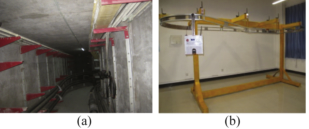
Fig.2
The model of cable tunnel inspecting robot systems.
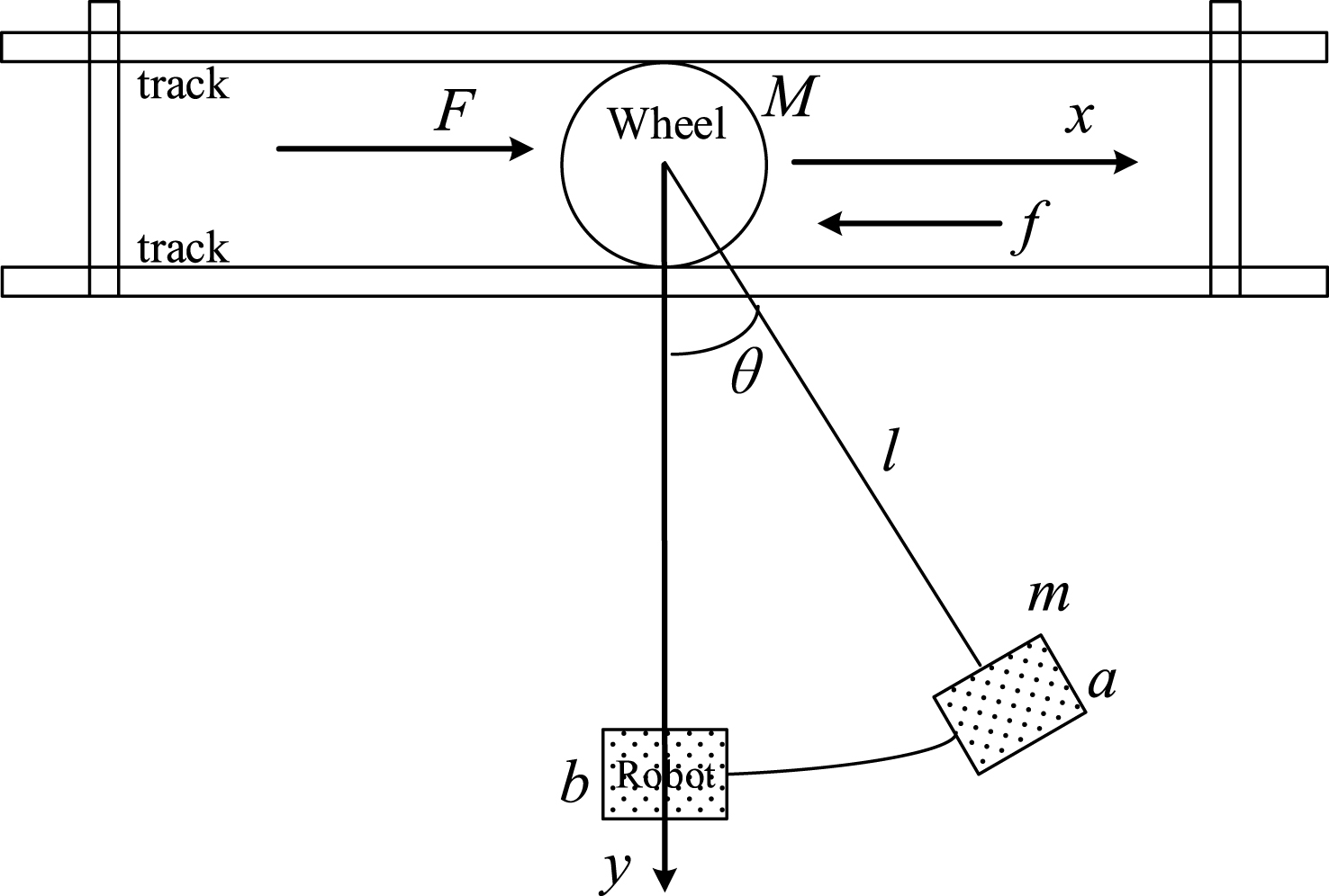
Fig.3
Fuzzy logic control structure.
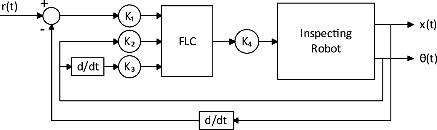
Fig.4
Control surface.
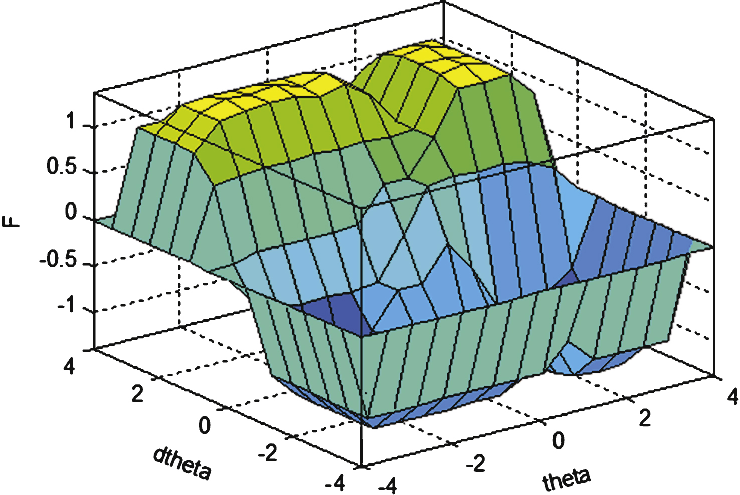
Fig.5
The model of hybrid system.
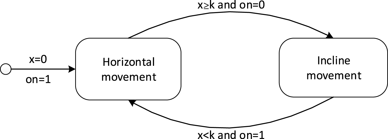
Fig.6
Stateflow design diagram.
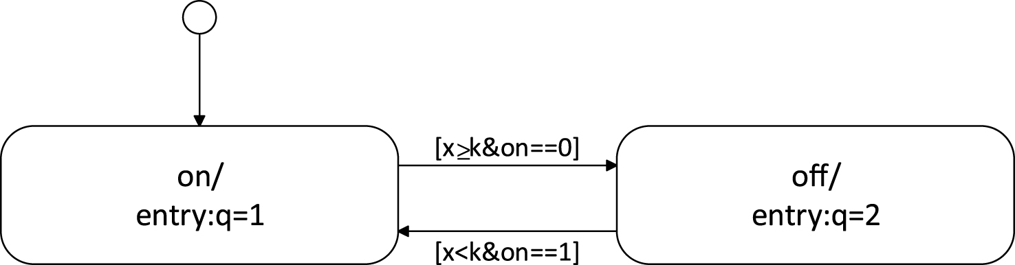
Fig.7
Hardware platform and IMU sensor.
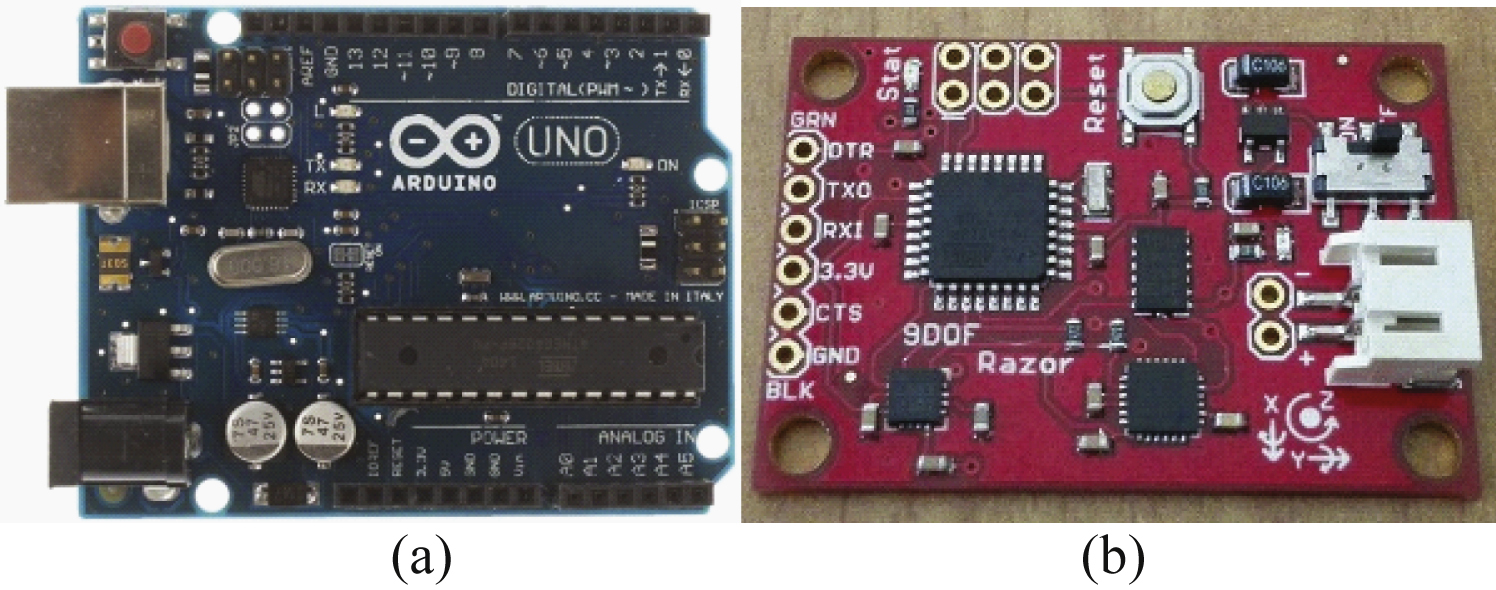
Fig.8
Response of velocity-track fuzzy control.
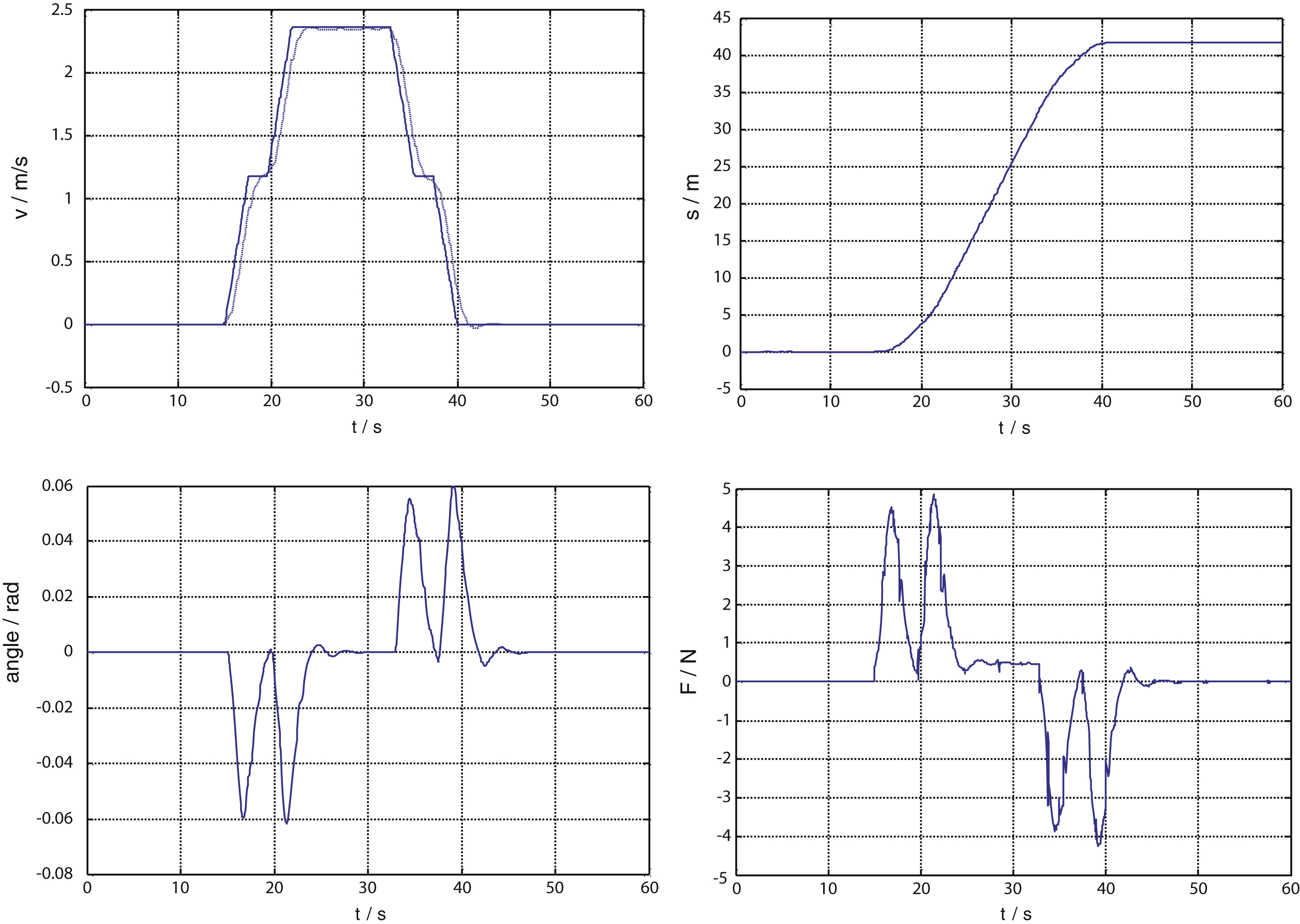
Fig.9
Response of velocity switching control.
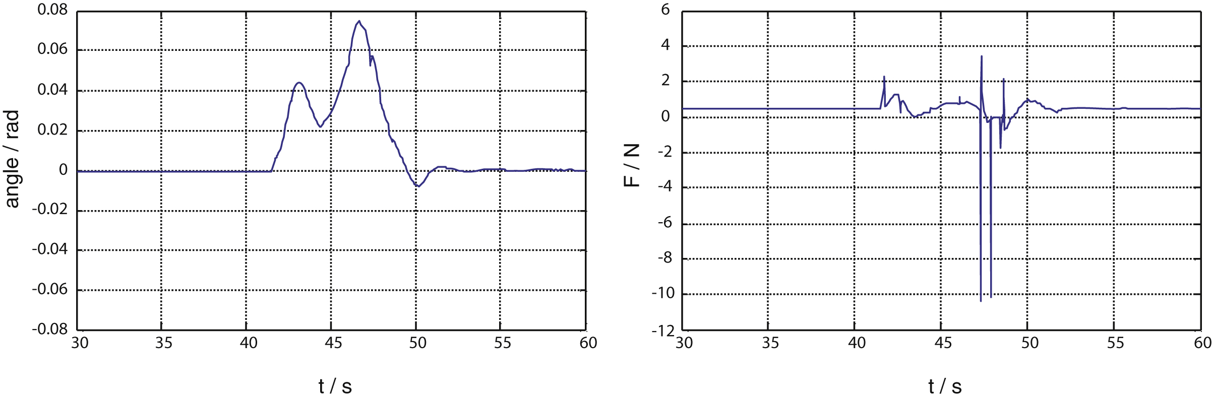
Fig.10
Response of the horizontal and incline movements.
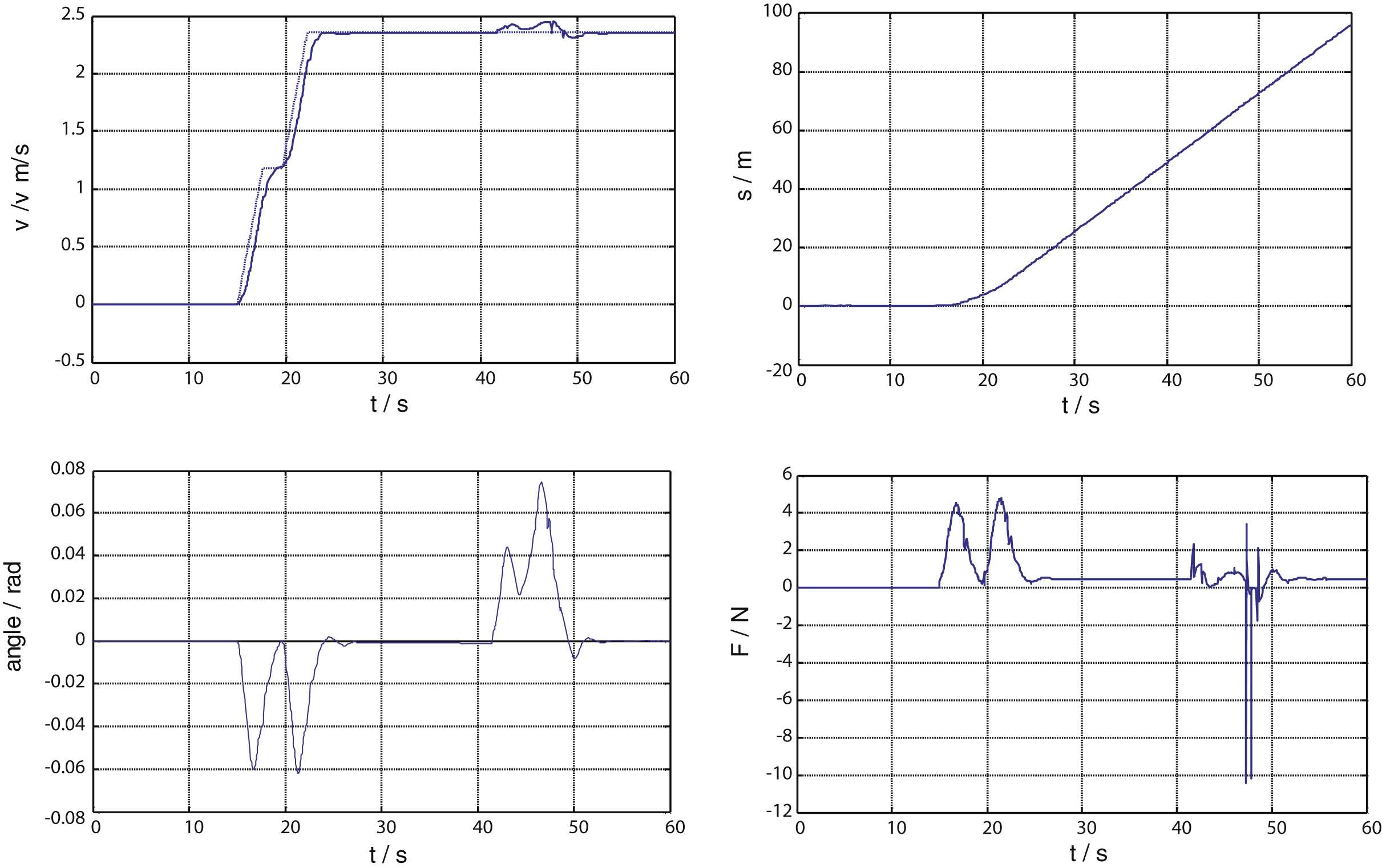
Table 1
Control rules
| F | NB | NS | ZE | PS | PB | |
| dΔx | NB | NS | ZE | PS | PB | |
| F | θ | |||||
| NB | NS | ZE | PS | PB | ||
| dθ | NB | NB | NB | NB | NS | NB |
| NS | NB | NS | NS | NS | NB | |
| ZE | NS | NS | ZE | PS | PS | |
| PS | PS | PS | PS | PS | PB | |
| PB | PB | PB | PB | PS | PB |


