Assessing the performance of an advanced integrated facade by means of simulation: The ACTRESS facade case study
Abstract
The growing demand for both building energy efficiency and indoor environmental comfort is leading to a substantial evolution of the traditional concept of the building envelope. The future building skin is required to be responsive and dynamic, actively regulating the flows of heat, light, air and water from outdoor to indoor and vice versa, in order to effectively respond to ever-changing climatic conditions, occupant comfort and energy efficiency requirements. In the framework of a decade-long research activity on Advanced Integrated Facade, AIF, a new Multifunctional Facade Module called ACTRESS has been conceived: the ACTive, RESponsive and Solar envelope is designed to play different roles through its ability to change its thermo-physical behaviour in order to suit the different environmental conditions. This paper briefly illustrates the ACTRESS MFM concept and its functional strategies, focusing on the simulation and the assessment of the performance of such a dynamic envelope. The numerical study was conducted in order to evaluate the potential energy savings achievable with such a facade and to evaluate different functional strategies and options. The evaluation of the performance in terms of energy savings was done at both component and whole-building level. Moreover this work presents an example of the applicability of Building Performance Simulation tools to the design of an innovative and dynamic facade system, discussing the capability of BPS software in simulating and evaluating the performance of such systems. The results show that the ACTRESS MFM can effectively reduce the total primary energy consumption of an office building up to 55% compared with a reference facade complying with national regulations. On the other hand modelling assumptions and simplifications are needed in order to evaluate the performance of such a system with BPS software, representing a barrier to the design and the adoption of advanced facade systems in the building industry.
1Introduction
“An environmental diode, a progressive thermal and spectral switching device, a dynamic interactive multi-capability processor acting as a building skin […], trading energy surplus for energy need […], adapting itself to provide best possible interior conditions […].” (Davies, 1981)
This is what Mike Davies, Roger Stirk Harbour partner architect, envisioned, more than forty years ago, on the basis of the latest technological developments in the field of material engineering. At that time, currently well-developed technologies using photovoltaic effect, photo, thermo and electro-chromic effect were just at their outset, but already inspiring architects and the building industry. Although Davies’ vision of ‘polyvalent wall’ could seem now much closer, as much more technological development and research has been carried out since then, how far are contemporary building envelopes from the environmental diode concept? And how far have design tools been developed in order to help designers at delivering and evaluating the performance of these concepts?
Nowadays the stricter environmental regulation for building energy efficiency brings designers back to a situation similar to the one that generated such a vision. In fact the idea of the environmental diode was partly generated by the designers’ attempt to answer with building envelope designs that were more conscious of the increased cost of energy caused by the 70’s oil crisis. The relevant interests generated by the facade is due to the key role that the building envelope plays in controlling the energy and mass flows from outdoor to indoor (and vice versa) and the possibility offered by the facade for solar energy exploitation. In fact there was a growing awareness that indoor environmental comfort could not be achieved, in an energy efficient way, demanding the whole need for indoor climate control to heating, ventilation and air conditioning (HVAC) systems, but that an energy conscious design of the building envelope was needed, in order to decrease the energy use of the HVAC systems, providing at the same time a comfortable indoor environment, in contrast with the uncomfortable indoor conditions and high energy consumptions created by modernist fully glazed building skins.
One of the first steps towards Davies concept was the introduction of Double Skin Facade (DSF), which became very popular in the nineties (Oesterle, Lieb, Lutz & Heusler, 2001). The superposition of a second external transparent skin, to the first one, materialized an air cavity, which could be exploited in different ways (i.e. thermal and sound insulation, ventilation, thermal buffering and sun shading purposes) (Compagno, 2002; Saelens, 2002; Knaack, Klein, Bilow & Auer, 2014). According to how the airflow and/or the shading devices are operated and managed, the facade can dynamically adapt to changing outdoor environmental conditions and occupant requirements, and be optimized for heating, cooling and/or lighting purposes (Poizaris, 2006). Moreover the introduction of DSFs allowed the designer to rethink the facade as part of the HVAC system itself (Stec & Van Passen, 2000) in order to reduce the energy consumption of the building.
Nowadays the EPBD recast (EPBD 31/2010) requires all new construction to be nearly Zero Energy Building (nZEB) by 2020 (2018 for public buildings). In order to achieve the nZEB objective, new concepts and technologies that can further improve the energy efficiency in buildings need to be developed and adopted by the building industry. IEA– ECBCS Annex 44 (2009) on Responsive Building Elements (RBE) demonstrated that the limitations given by the existing technologies could be overcome by revisiting the concept of the building as a ‘static’ system. In fact, especially as far as temperate climates are concerned, the requirements posed by the nZEB target cannot be simply fulfilled by means of an increased thermal insulation and air tightness of the building envelope. For that a ‘responsive’ and ‘dynamic’ behaviour is required, with the aim to continuously change the interaction between the building elements (e.g. walls, roof, windows etc.) and the outdoor (and indoor) environment, on different time scales (i.e. seasonal, diurnal, hourly and instantaneous). Among the RBE concepts, identified by the IEA-ECBCS Annex 44, Advanced Integrated Facades (AIFs) are probably one of the most promising technologies (Quesada, Rousse, Dutil, Badache & Hallé, 2012a, b). This picture is supported by the fact that important players in the field of the facade have started to develop advanced integrated modular facade systems (Multifunctional Facade Modules – MFMs). These are almost ‘self-sufficient’ building skins that present a dynamic behaviour, incorporating different technologies (e.g. ventilation systems, decentralized heating/cooling units, heat exchangers, energy supply devices, energy storage, lighting equipment, shading devices, ventilated cavities) and interacting with the other building services in order to reduce the energy consumption and maximize the indoor comfort conditions (Favoino, 2010).
Another step towards the adaptive building envelope concept was done, thanks to new developments in material science applied to the building envelope, by introducing in the building skin new materials and devices with adaptive and responsive features, as well as energy producing materials and devices, like photovoltaics. These new materials are often referred to as ‘smart’ or ‘intelligent’. Ritter (2007) defined as ‘smart’ those materials that show reversibly changeable physical properties in response to some physical (thermal, optical, mechanical) or chemical influence. Among these are electro, thermo and photo-chromic, thermoelectric and thermostrictive materials, Shape Memory Alloys (SMA) and Phase Change Materials (PCM). While Aschehoug, Andresen, Kleiven and Wyckmans (2005) refer to ‘intelligent’ to describe any material or device that has the ability to adjust to changing of boundary conditions due to a subsystem that is able to sense and control the device. In fact the adaptive or responsive feature itself does not assure effective operations, consequently increasing energy efficiency and occupant comfort. In fact to reach an effective performance, different components of an advanced facade need to adjust to changing environmental conditions synergistically, cooperating together and with other building services. This is a non-trivial task, as conflicts and trade-offs need to be addressed in order to provide energy efficiency and a comfortable environment at the same time. Different examples of climate adaptive building skins using smart materials and/or intelligent devices could be found in Loonen, Trcka, Cóstola and Hensen (2013) and in Favoino (2010).
Even if it is intuitively understandable that a higher performance is achievable by using a building skin which is able to adapt to changing environmental conditions and occupants’ comfort requirements, designing and operating such a complex system is a challenging task. Moreover the quantification of the performance of the different components, and of the facade as a whole, is required on a real time basis when operating it. These issues imply two sets of problems. The first one concerns the definition of the performance of dynamic components, as ‘static’ features like U-values and g-values are no longer meaningful for this kind of building envelopes. The second one concerns the correct simulation of the performance of such systems in order to effectively design and operate them. Using Building Performance Simulation (BPS) enables to simulate all the possible configurations of the large number of components included in the facade, given a set of boundary conditions (environment and occupants) across the boundaries of multiple physical domains (thermal, luminous, acoustic etc.). By doing so, the virtual model of the building created within the software can be used to predict building performance for different purposes (i.e. research, design, diagnosis, operation), provided that the tool is used in the right way. While the first set of problems has already been explored for some AIF designs (i.e. double skin facade by DiMaio & Van Paassen (2001) and Corgnati, Perino & Serra, 2007), the application of BPS in relation to adaptive building envelope is still largely unexplored (Loonen, Singaravel, Trcka, Cóstola & Hensen, 2014). In fact, inspired by Davies’ vision, many new concepts of multifunctional and adaptive facades have been developed (Favoino, 2010; Loonen et al., 2013), their adoption in the building industry is restricted by many barriers, one of them being the inadequacy of BPS tools in representing their performance (Loonen et al., 2014).
In the frame of a research activity aimed at the development of a solar and active building skin of the future, a new concept of MFM has been conceived and a prototype realized to experimentally assess its energy and comfort performances. The new facade module, named ACTRESS – ACTive, RESponsive and Solar – was conceived starting from a decade-long first-hand experience and a literature survey (Goia, Perino, Serra & Zanghirella, 2010).
The main aim of this paper is to quantify the energy performance of the ACTRESS MFM facade when it is integrated in the building; this is achieved by means of building performance simulation. The secondary aim is to map and analyse the limitations of current BPS tools in the evaluation of this kind of innovative AIF technologies, integrating adaptive building envelope components. To this last aim the ACTRESS MFM can serve as a case study, given the high level of integration and the adaptive behaviour of some of its components, and the complexity of its operating strategies.
In the second section of the paper the ACTRESS MFM and its operating strategies are detailed. In Section 3 the software framework for building performance simulation of the ACTRESS MFM is presented, while in Section 4 the expert modelling needed for the dynamic component in the MFM is described. In the fifth section the metrics to assess the components’ thermal performance and the energy performance of the building integrated ACTRESS MFM are detailed, and the results are presented in the sixth section. Finally the limitations and requirements for BPS at modelling this kind of advanced integrated building envelope are discussed.
This numerical study was done to verify and optimize the design of the ACTRESS module prior to prototyping. This case study, although not representing all the panorama of possible AIF and MFM designs, and all the panorama of BPS tools, can give a valuable insight in the methods, possibilities and restrictions of BPS, related to the evaluation of the performance of more advanced, integrated and responsive facades.
2The ACTRESS multifunctional facade module
2.1ACTRESS MFM design and components
Starting from first-hand research experience on AIFs and a literature survey, a new facade module has been conceived, named ACTRESS – Active, Responsive and Solar – facade module (Favoino, Goia, Perino & Serra, 2014).
The main goal of the ACTRESS facade module is to overcome the limitation given by the current AIF technologies and to assess the effects of an adaptive Multifunctional Facade Module (MFM) on building energy savings and indoor environmental quality. The aim of the MFM is to realize an (almost) self-sufficient building skin that integrates different components and interacts with other building equipment to maximize the energy and environmental performance by adjusting to changing environmental conditions and occupants’ requirements. In order to develop an effective/efficient MFM system that represents a step forward in the field of AIFs, the weak spots of present-day AIF technologies have been used as a starting point during the concept phase (Goia et al., 2010; Favoino et al., 2014).
The ACTRESS MFM has been designed as a prefabricated unit of one storey high, of total frontal dimensions 1500 mm x 3500 mm. It is made of two different sub-systems (Fig. 1): a Transparent Sub-Module (TSM) and an Opaque Sub-Module (OSM). Conventional AIFs present a large transparent surface, usually equipped with a Double Skin Facade (DSF) (Aschehoug, 2009; Poizaris, 2006). Opaque surfaces are usually avoided or reduced to a minimum extent. On the contrary, MFM prototypes usually adopt a different balance between transparent and opaque surfaces. After some preliminary investigation, carried out by numerical analysis with the software EnergyPlus (Goia, Haase & Perino, 2013), results showed that a 1:1 ratio is a good balance between the glazed and opaque envelope surface in order to minimize energy consumption for heating, cooling and lighting in temperate climates. This strategy allows the heat capacity of the building skin to be increased and the total heat transfer coefficient of the MFM to be decreased, compared to highly glazed MFMs and AIFs.
The OSM is constituted by an Opaque Ventilated Facade (OVF), equipped with four axial fans for the mechanical (fan-assisted) ventilation of the cavity (dimensions of the cavity: 600 mm width x 120 mm depth x 3400 mm height). Airflow within the cavity can be managed according to the desired integration with the building services and operation, as explained in paragraph 2.2. The outer surface of the OSM is made of three glass laminated PV panels (amorphous silicon PV, nominal power = 29 W, G-value = 0.27, U-value = 5.0 W/m2K) for power production within the MFM. The back of the cavity is made of a multi-layer opaque wall panel. Along with some gypsum-board layers, providing mechanical resistance to the opaque sandwich, a highly insulating VIP layer (thickness of the VIP panel = 25 mm, λ = 0.005 W/mK) is included. It is coupled with two layers of Phase Change Materials (PCMs). The two PCM layers are placed between the VIP and the indoor environment. An Electrically Heated Foil (EHF) is positioned in between the two PCM layers for PCMs on-demand activation (heating strategy). The transparent sub-system is made of two glazing systems. The larger bottom one is a triple low-e coated glazing with Argon (U-value = 1.0 W/m2K, g-value = 0.3). The outer cavity of the triple-glazing hosts a high reflective, low-e coated venetian blind, to control the solar and light transmission. The smaller top one is a triple-glazing, whose outer cavity is filled with aerogel (λ = 0.009– 0.012 W/mK). This material improves the performance of the glazing in terms of thermal resistance and allows exploitation of natural light avoiding glare discomfort (due to its translucent appearance).
In Figure 1 the concept design of the MFM is shown together with a prototype realized for experimental assessment of its performance in real world environmental conditions. First results from the winter experimental campaign are presented in Favoino et al. (2014).
2.2Operating strategies
The MFM has been designed to enable different adjustments in respect to ever changing climate and indoor comfort requirements, on a seasonal, daily and hourly basis. Moreover the module enables different interactions with the HVAC system.
In particular the OVF, within the OSM, can be operated as a Supply Air (SA), Thermal Buffer (TB) or Outdoor Air Curtain (OAC) facade (Poizaris, 2006), depending on the season, the building location, the orientation of the facade and on the degree of integration between the facade module and the building services.
When talking about the OSM, the following operating strategies have been proposed:
• In winter, the ACTRESS MFM could work both as a SA facade (1, Fig. 2) or to provide a thermal buffer TB (5, Fig. 2) to reduce respectively either ventilation losses and heat losses, or heat losses only;
• In summer, the ACTRESS MFM could perform as an OAC facade, in order to remove the unwanted solar gains during summer (5, Fig. 2). OAC mode could be performed by means of Natural Ventilation (NV) or is Mechanically Ventilated (MV) when higher solar irradiance heats the facade (1, Fig. 2). The decrease of the temperature of the PV layer caused by the ventilated cavity of the OSM will reduce the power losses of the PV due to the temperature effect, thus improving their performance (2, Fig. 2).
As far as the power produced by the PV panels and the role of the PCMs are concerned, the following hypotheses about the operations have been considered:
• In winter, the power generated (2, Fig. 2) can be used to heat, by means of the Electric Heating Foil (EHF), the PCM contained into the sandwich wall panel. PCMs would then act as a solar Latent Heat Thermal Energy Storage LHTES (4, Fig. 2). PV generated energy could also balance the energy used to operate the shading devices and the lighting system in the enclosed room (3, Fig. 2);
• In summer, the PV panels could provide additional power to activate the fans for the mechanical ventilation of the OSM (3 and 1, Fig. 2). The extra current can be released to the electrical system, since no power storage devices have been adopted in summer mode. PCMs could operate in summer as a ‘simple’ and ‘passive’ indoor environmental climate moderator (i.e. smoothing the peak temperatures of the indoor air and reducing the cooling loads) (4, Fig. 2).
The lower part of the TSM (in particular the venetian blind in the cavity of the TGU) can be operated in winter in order to avoid glare whilst maximizing the entering solar heat gain; in summer to avoid glare, minimize the solar energy entering the environment and maximize the amount of natural light through the glazed portion of the facade and view to the occupant.
The control of the facade during mid-season is one of the hardest tasks as far as the building management system is concerned. Different strategies either characterizing the summer or winter mode could be necessary during the same day, so that the management system should be able to simulate the energy and comfort performance of the facade and decide which operating condition to adopt depending on climate conditions. The detailed design of the control system for the MFM is out of the scope of this paper; therefore it will not be presented.
3Building performance simulation of ACTRESS MFM facade
A major challenge faced during the design process of this kind of building envelope components is the lack of integrated design tools that could enable the effective prediction of the thermo-physical behaviour of the MFM, together with the energy performance of a building that adopts this technology (Loonen et al., 2014; Goia & Cascone, 2014). Commercially available software products are either too much specific (like most of the CFD codes and FEM codes) or too much generic (like whole building performance simulation tools, whole-BPS tools). The first typology of software could be used to obtain detailed information on the behaviour of some sub-components, but is not suitable to obtain the overall picture of the performance of the AIF as a system. On the contrary, whole-BPS tools are useful for assessing the overall performance of the building in terms of energy consumptions and occupants comfort, but present serious limitations when complex components (like an AIF, or an adaptive building envelope system in general) need to be described and integrated into the model. As a result energy assessment obtained by means of whole-BPS tools can be quite far from the actual performance of a building that integrates AIFs and RBEs, giving at the same time very limited information about single MFM components performance. Moreover whole-BPS tools are rarely integrated with Building Information Modelling (BIM) tools, thus making the modelling and performance evaluation a costly and laborious process and subject to modellers’ assumptions and errors (Bazjanac, 2008).
The assessment of the performance of the ACTRESS MFM facade, in terms of whole building energy performance and components thermal performance, can be used as a case study in order to evaluate the ability of BPS tools at assessing the performance of an advanced MFM and to investigate the main requirements and limitations of these tools for this purpose.
The energy performance of the ACTRESS MFM and of its components was investigated through a numerical analysis, carried out with the help of two integrated software tools: Autodesk REVIT (BIM tool) and IES VE (whole-BPS tool).
A BIM parametrical model was developed with REVIT for the ACTRESS MFM together with the prototype manufacturer in order to provide sufficient flexibility in the architectural design and manufacturing of the facade, and supporting information to the other stakeholders in the facade design process, among the other facade consultants and Building Energy modellers (Voss, Jin & Overend, 2013). Full details of the ACTRESS BIM modelling could be found in Favoino (2010). A pre-assessment of different commercial BPS tool capabilities at evaluating AIF energy performance based on Crawley, Hand, Kummert and Griffith (2008) indicated IES VE as one of the most complete BPS tools available on the market to be validated for this task, while differently from other validated whole-BPS tools it was interoperable with BIM software in general and with Autodesk Revit in this particular case. Figure 3 details how the ACTRESS MFM was divided into different subcomponents for modelling and performance evaluation purposes in the two different software systems. It was later verified that the two software systems were not fully interoperable on a certain level of information, determining a waste of resources in an accurate modelling of the ACTRESS facade in REVIT. The level of interoperability between Revit and IES VE is only related to geometry information (surfaces and volumes), while all the different OSM and TSM sub-components (air cavity and opening, wall layers, blind etc.) and material properties were not imported into IES VE (Favoino, 2010), therefore re-modelling of lost information was required in the two different software systems.
As far as the ACTRESS energy modelling and performance evaluation activity is concerned the main limitation of IES VE software was represented by the lack of accurate models regarding the OSM sub-module, in particular to the OVF and to the LHTES system facing the indoor environment. Therefore equivalent dedicated models were required for both components and some off-line calculations were needed in order to assure an accurate modelling and to integrate the operations of some components. The modelling assumptions for the components of the OSM (OVF and LHTES) and the method for the energy performance evaluation is detailed in the next sections and mapped in Figure 3.
4Modelling of ACTRESS MFM
4.1Opaque ventilated cavity
Different methods are available to accurately model cavity ventilation in double skin facades, according to the level of accuracy needed, the kind of ventilation and the different elements integrated in the cavity. According to Hensen, Bartak and Drkal (2002) the simulation of the air flow in the cavities can be done by means of Computational Fluid Dynamics (CFD) or of the Airflow Network Method (ANM). The CFD code is able to perform many tasks that the network modelling will never achieve. However, due to the complexity of the CFD simulation, the amount of calculation power needed, the restricted steady state boundary conditions, the absence of movable shading device in the air cavity in the ACTRESS case and the nature itself of the performance assessment needed, its use is not necessary at this design stage. Furthermore ANM is much more easily integrated into whole building energy simulation models, although much progress has been made in the coupling of CFD and whole building energy simulation models (Zhang, Lam, Yao & Zhang, 2013). For ANM modelling different approaches are possible. Saelens (2002) performed an investigation of the accuracy change with stepwise enhancement of the network model, from the simplest case of a single zone model, to the more complex case of the cell centred control volume method with the convective and radiative flows treated separately. According to Saelens (2002) the best ANM is based on a cell centred control volume method, in which the cavity is vertically subdivided and in which the temperature of the cavity control volume is represented by a bulk temperature. It is assumed that enthalpy flows only occur along the vertical direction, this restricts the use of this model to multiple-skin facades with roller cavity blinds only, or no cavity shadings.
In this case the ANM control volume method was used in order to model the OVF cavity ventilation. An additional room, vertically subdivided, was created for the cavity, and its geometry had to be modified in relation to the calculation method used by IES VE for natural ventilation. In particular it adopts a cell centred control volume method, where the control volume is the thermal zone defined in the software, represented by a bulk temperature. The calculation of the airflow between two connected zones is based on the flow characteristics of openings that are small in relation to the spaces they connect (IES VE ltd., 2010). Therefore in order to achieve a good model reliability, adjustments to the opening dimensions and cavity thickness were necessary. In particular, the sectional area of the cavity was set accounting for the frictional resistance of the cavity walls and obstructions using the Colebrook-White equation for rough duct in turbulent regime:
(1),
(2),
In reality, the frictional resistance is evenly distributed along the duct, but in MacroFlo, as in all the simulation tools adopting the ANM model, it has to be aggregated into a discrete opening, connecting the two thermal zones. In order to achieve a good model a subdivision of the cavity in different interconnected zones, vertically separated, is necessary. The subdivision of the cavity consisted in dividing the ACTRESS ventilated cavity in five sub-volumes (Fig. 5), in order to measure the bulk air temperature at the air cavity inlet and outlet, as well as a bulk surface temperature for each one of the 3 PV panels of the outer glazing confining the cavity. To calculate the equivalent cavity opening area we can refer to the flow conservation principle:
(3),
(4)
Therefore the ventilated cavity thickness is increased from 12 to 28 cm in order to account for the capacity losses due to the frictional and obstruction resistance of the cavity.
As far as MV is concerned, four fans were placed at the cavity exhaust section, with a peak capacity of 94,5 l/s, according to data from manufacturers. When the fans are powered, both mechanical and natural ventilation are accounted for into the cavity. The opening schedule of the cavity inlet and outlet for natural ventilation follows the occupation schedule, while as far as mechanical ventilation is concerned, since the fans are directly powered by the PV, the minimum solar irradiance (Gfan) able to power a fan at peak capacity was calculated (i.e. Gfan = 20 W/m2). For values higher than Gfan each fan is progressively powered at peak load, while for lower values the capacity is proportionally modulated.
4.2The LHTES system
The LHTES system is composed by the two PCM layers with the interpose EHF, which is heated by the PV harvested energy during winter, while it is separated from the air cavity by the VIP panel (Figs. 1 and 3).
As far as the PCM layer is concerned, few commercially available software products allow, as part of the standard routine, to model directly a PCM integrated with whole building energy simulation. The key feature of PCM is to absorb energy as latent heat rather than sensible heat over a small range of temperatures; hence, a PCM exhibits few temperature rises when in the melting process. Different modelling problems need to be solved in order to correctly simulate the PCM behaviour, i.e. hysteresis between latent heating and cooling cycles, different melting and freezing peak temperatures and variation of the heat capacity with temperature, sub-cooling phenomena (Zalba, Marín, Cabeza & Mehling, 2003). Nowadays different validated models are available but few of them are implemented on commercial software (AL-Saadi & Zhai, 2013; Castell, Medrano, Castellón & Cabeza, 2009).
In this case no building envelope integrated PCM model exists in IES VE, since it is not possible to set the specific heat capacity of a material as a function of the temperature, and the latent heat storage of the PCM cannot be modelled unless simplifying assumptions are taken. According to Ibanez, Lazaro, Zalba and Cabeza (2005) and Kendrick and Walliman (2007) it is possible to simulate the PCM layer with no need to model the state change within the material, although with some limitations. Both authors model the PCM as an ‘active layer’, whose temperature and heat transfer rate is controlled by means of a fluid, water or air, having the same temperature of the melting temperature of the PCM. This model is able to simulate only ultra-pure PCMs, that is PCMs not showing a region of temperatures where melting takes place, but a unique defined temperature. According to (Ibanez et al, 2005; Castell et al., 2009), good agreement with experimental data is achievable with such a model, provided that laboratory characterization of the material properties is done, and provided that the PCM is pure paraffin.
The ‘active layer’ method, or so-called ‘conditioned cavity method’ (Kendrick & Walliman, 2007), has been adopted to model the PCM layer in IES VE. In this method, a virtual cavity, that simulates the PCM layer, is maintained at a set-point temperature (which corresponds to the nominal melting temperature of the chosen PCM) by means of an ideal HVAC system. Controlling the airflow-delivered energy according to the total heat capacity of the PCM layer is very time consuming, as an iterative process is required. This restrains the simulation to no more than one month, as a schedule controlling the fictitious HVAC management system needs to be set for each different day. That is why it was chosen, in order to perform a yearly simulation, to control the air temperature inside the active layer always at the PCM melting temperature. When such an approach is adopted, an infinite latent heat storage capacity is assumed for the PCM layer, requiring further verification to ensure a good reliability of the results. This verification implies an energy balance to be performed on the PCM: i.e. the sum of the ‘conditioned cavity’s’ heating and cooling loads, on a daily basis, needs to be equal or lower than the actual latent heat storage capacity of the PCM. Or, in other words, the areas below the heating (red line in Fig. 4) and cooling (blue in Fig. 4) power profiles of the fictitious HVAC system simulating the PCM, are required to be equal or lower than the PCM total latent heat capacity on a daily basis, taking into account the balance between the two areas of the previous day as well. The heating loads represent the heat which is supplied from the PCM to the room, while the cooling loads represent the heat which is absorbed by the PCM from the room. In fact if the amount of heat supplied or released to the conditioned cavity exceeds the total latent heat capacity of the PCM designed, it means that the real temperature of the PCM should be higher than the equivalent model simulated. This verification can also be used as a design tool to estimate the optimal quantity of PCM to be used, in fact the energy balance of the PCM layer is a way to verify that the amount of PCM designed is sufficient to provide the required performance. The proper approach that provides the foundation of the conditioned cavity method implies the modelling of an infinitesimal volume cavity, whose wall surfaces have a (almost) null thermal resistance (at least lower than 10–4 m2KW–1) and no heat capacity (the sensible heat capacity is neglected and the entire latent heat capacity is accounted for in the cavity loads); the cavity boundaries themselves exhibit a thermal resistance equal to the one of the PCM layer.
The ‘conditioned cavity method’ approach can be used during summer operation, with the PCM used as a passive storage media (LHTES), or during winter operation, in which the PCM stores the energy harvested by the PV (Solar LHTES). In winter operation also the energy harvested by the PV must be included in the daily energy balance of the PCM required by the ‘conditioned cavity method’. This energy balance on the fictitious layer of the PCM cannot be done in IES VE, so that an off-line calculation is performed.
5Energy performance assessment methodology
The energy performance of the ACTRESS MFM module is evaluated on two levels: at component level and at whole building level (Fig. 3, bottom part). At component level the indicators to measure the thermal performance of dynamic facade sub-components are evaluated (OVF and LHTES) according to the different possible operating strategies. The thermal performance of the TSM components is not detailed in this section, as it can be easily done in terms of thermo-optical properties of the glazing system itself (which is already detailed in Section 2.1). At whole building level the total primary energy consumption of an office reference room adopting the ACTRESS facade (including OSM and TSM, with different operating strategies of the OSM) is compared to an office with a reference facade.
5.1Component thermal performance assessment
Besides the overall building energy demand, the performance of the single components of the ACTRESS MFM needs to be evaluated. As far as the OVF is concerned, different ventilation strategies are assessed and compared: Thermal Buffer (TB), Natural Ventilation (NV) and Mechanical Ventilation (MV). Natural stack ventilation (NV) is used in heating mode, for TB or to preheat outside air (SA strategy); NV and MV is used in cooling mode, to remove the excess heat from the facade (OAC strategy). In the mid-season both strategies can be used, and the performance and the correct control strategies are evaluated for both cases. The performance of the ventilated cavity was estimated by means of dynamic parameters (DiMaio & Van Paassen, 2001 and Corgnati et al., 2007), i.e. the ‘dynamic insulation efficiency’ ɛ, and the ‘preheating efficiency’ η.
The dynamic insulation efficiency ɛ measures the ratio between the amount of heat load removed by the cavity ventilation QR and the total heat load impinging the facade QIN, being a measure of how the facade is able to remove the unwanted external heat gains in the indoor environment in the cooling season:
(5),
(6),
In the OSM, the PCM layer is coupled with an EHF in order to have an ‘on-demand activation’ available during winter (Solar LHTES), while it can be used ‘passively’ during summer, reducing the cooling load in the building (LHTES). In winter the EHF is powered primarily from the PV panels placed on the outer surface of the OSM, but connection with the electrical grid can be available. A complete evaluation of the LHTES system is carried out according to the energy balance of the PCM needed to implement the ‘conditioned cavity method’, i.e. the daily energy balance between heating and cooling energy in the PCM ‘conditioned cavity’ is not violated (cfr. Section 4.2). During summer heating and cooling energy of the PCM ‘conditioned cavity’ are accounted in the energy balance, while in winter the PV converted energy is included as well. The performance of the system as well as the accuracy of the model is measured by the time percentage of the PCM being in the melting phase; the higher this percentage the more reliable the model and the more effective the LHTES design is in summer and in winter.
5.2Whole building energy performance assessment
The overall building specific primary energy demand, EP [kWh/m3y], of an office equipped with the ACTRESS facade module was estimated and compared against the one of an office equipped with a reference facade. The two identical 30-m2 office rooms (6 m × 5 m × 3,5 m) were located in Turin (Lat. 45°N, Long. 7.65°E), Italy. The ACTRESS facade (four modules are used to cover the entire office room elevation) faces South and the other walls are adiabatic (i.e. the office room is adjacent to other identical rooms on all the other surfaces, except the exposed facade). The facade of the reference office room is made of a heavy-weight wall and presents the same glazed area as the ACTRESS one (Fig. 4). The main physical properties of the reference envelope comply with local building regulations for the climatic zone of Turin (Uopaque = 0,35 Wm–2K–1, Uwindows = 1.97 Wm–2K–1). The internal heating loads are 20 Wm–2 (including people, lighting and appliances) and 2 Wm–2 in a non-occupation period, considering an occupation density of 0.1 person/m2. The occupation period is 8:30– 6:30 pm, Monday to Friday. The indoor temperature set-point is 21°C during winter and 26°C in summer (with 14°C and 40°C night set-back respectively), with 1.4 l/s per person as primary ventilation.
6Results
6.1Opaque ventilated facade thermal performance
The performance of the following cavity ventilation strategies of the OSM is evaluated: Thermal Buffer, Air Supply in Natural Ventilation mode and Outdoor Air Curtain in Natural and Mechanical Ventilation mode. The comparison between the exhaust air temperatures under the different ventilation strategies (Fig. 6) shows a relevant reduction of the cavity central air bulk temperature of nearly 20°C comparing TB and MV ventilation. This reduction affects the energy performance of the facade during both cooling and heating season and the PV efficiency. In fact the PV modules’ temperatures are reduced up to 10°C in winter and in mid-season, and up to 15°C in summer, when MV is adopted rather than NV. Moreover, if compared to a non-ventilated PV panel placed on a wall, the peak temperature is reduced to about 40– 50°C. Comparing the ACTRESS PV system and a conventional PV module without any integrated ventilation (Fig. 7), both in the heating and cooling season, it can be observed that the ventilation improves the PV efficiency up to 10% , with an average value of 5% . MV shows a better performance than all other ventilation strategies, both in the cooling and the heating season, increasing PV efficiency of 2% compared to NV and 3% to TB, on the average (Fig. 7).
Figure 8 shows the cumulated frequency (during the occupation period) of the dynamic insulation efficiency of the two ventilation modes in OAC strategy (cooling and mid-season). It measures the amount of heat that is removed from the facade by means of the ventilation. During the cooling season, the facade is able to reduce the entering heat gain by more than 60% , on the average (50% of the occupation period), while MV profiles an average improvement of 10% compared to NV.
The cumulated frequency analysis for the heating season (Fig. 9) quantifies the effectiveness of the cavity in preheating the air during winter. In TB mode, the air is confined into the cavity; therefore, even with a very high preheating efficiency (30% of the time higher than 100% ), no air can be supplied to the indoor environment, but the heat losses can be consistently reduced in this way. On the contrary, in NV mode the preheating efficiency is not sufficient to supply the air directly into the indoor environment (preheating efficiency higher than 100% ), but if used as Supply Air for the HVAC system it is able to provide nearly 20% of the heating plant load during wintertime. The best ventilation strategy during the heating season will be evaluated looking at the overall energy consumption during the heating season of the office room, as the preheating efficiency alone is unable to measure the reduction of heat losses through the envelope and by means of ventilation, in terms of total energy consumption.
During the mid-season heating and cooling loads often occur within the same day. For this reason the cumulated frequency distribution is analysed for both parameters ɛ and η. Figures 9 and 10 reveal that the preheating efficiency increases during the mid-season with respect to winter (in NV mode with SA strategy), as the outdoor air temperature and the solar irradiance are higher than in winter. When η reaches an adequate value (e.g. η ≈100% ), it is possible to supply fresh air to the indoor environment directly from the cavity. A dedicated control is necessary to prevent an increase in the cooling loads from occurring (e.g. when η⪢ 100 % and cooling demand is present).
6.2LHTES thermal performance
In order to select the optimal quantity and type (nominal melting temperature, TPCM) of the PCM to be used in the ACTRESS facade module, several simulations were run to test the performance of the following nominal melting temperatures: TPCM = 23°C, 25°C, 26°C and 27°C.
The results of the simulations performed to select the proper amount and the nominal melting temperature of the PCM (and to test the model reliability) are shown in Figure 11 (cooling season, ‘passive’ use of PCM). The TPCM = 25°C is able to completely absorb (nearly 100% of the time) the factitious heating/cooling load of the virtual cavity, if at least 2.5 kg/m2 are used. This combination represents the optimal configuration of the system, as a PCM with a higher TPCM has a worse behaviour than the optimal solution (it is not completely melted for a longer period); a PCM with a lower TPCM is always melted as the sum of the heating/cooling daily energies exceeds the latent heat storage capacity of such a PCM.
As it is explained in paragraph 3.1 a measurement of the model reliability is also a proper method to select the best performing PCM melting temperature related to a certain strategy (use of PCM in a passive or active way), so that the best melting temperature choice in summer is 25°C, with a temperature set point of the HVAC system in the room of 26°C. A higher or lower PCM melting temperature would result in a higher PCM quantity required for good model reliability and effective PCM design. In Figure 12, a detailed analysis on the behaviour of the optimal solution is shown for different seasons. It can be noticed that, during the occupational period, the 2.5 kg/m2 PCM is maintained within the melting range for about 91% , 95% and 97% of the time in summer, mid-season and winter, respectively.
The coupling between the PCM layer and the PV power production has been investigated during the winter season only, since the aim of this system is to store a certain amount of energy available during the daytime for heating purpose (heating season, ‘active’ use of PCM). The influence of the different amount of PCM (MPCM) with different PV panel surface was investigated too, i.e. MPCM from 0.5 kg/m2 to 4 kg/m2 (in steps of 0.5 kg/m2), in combination with three possible PV panel surfaces (i.e. SPV = 1.67 m2, 2.50 m2, 3.34 m2).
Considering the optimal summer design solution (PCM with TPCM = 25°C, MPCM = 2.5 kg/m2), on seasonal basis, it can be noticed that the PCM layer is able to store, by means of latent heat, 82% of the energy produced by a 1.67 m2 PV surface, which is 50% of the total ACTRESS surface (Fig. 13). If the PV surface would be increased (i.e. SPV = 2.50 m2, or 3.34 m2, 50 and 100% additional equivalent area respectively, to be placed on the roof), a lower percentage of the PV-converted energy could be stored within the PCM layer (nearly 75% and 40% , respectively). If MPCM = 4 kg/m2 would be used instead, the entire amount of energy generated by the 1.67 m2 PV surface could be stored, in the latent heat capacity of the PCM layer.
The evaluation of the proper amount of PCM against the PV surface is mainly based on three parameters, which relationship is rarely linear, so that the step-wise variation of PCM amount or of PV surface is not proportional to the variation of the time percentage in the melting phase. The three main variables affecting these curves are the daily amount of latent heat storage potential available for energy storage in the PCM layer, the amount of solar energy converted by the PV, and the indoor conditions (internal loads and solar free gains) affecting the amount of heat that could be discharged daily from the PCM.
6.3Whole building energy performance (PE)
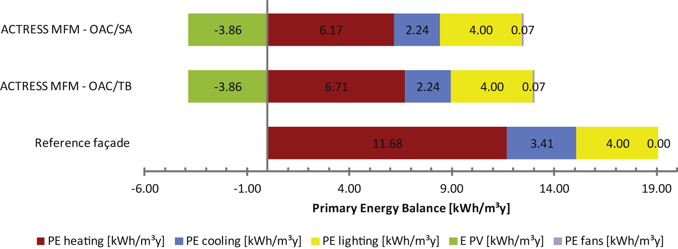
The total and the break-up primary energy consumption of the office equipped with the ACTRESS facade and with the reference facade are compared in Fig. 14. Adopting the Outdoor Air Curtain strategy during summer and TB in winter, the overall reduction of the primary energy demand EPTOT is 52% , i.e. from 19.1 kWh/m3y to 9.1 kWh/m3y. A considerable decrease in heating loads EPh is also observed (almost 53% ); this can be associated to the use of PV energy to activate the PCM, together with the reduce of heat losses due to the Thermal Buffer strategy in the OSM. Furthermore, it is remarkable how the electric consumption for lighting and appliances, on an annual basis, can be nearly completely covered (ca. 95% ) by the solar energy converted by the PV with the designed area of 1.67 m2 (the energy released into the PCM layer and the energy required for the cavity fans are already included in the energy balance). The possibility to exploit the air that is preheated by the OSM cavity as a supply air for the HVAC system (during winter and mid-season) was assessed by means of a dedicated simulation. With this configuration, a further reduction in the PETOT can be achieved (from 9.1 kWh/m3y to 8.5 kWh/m3y), resulting in a total energy saving of about 55% in comparison to the reference room just by substituting the reference building envelope with the ACTRESS MFM.
7Limitations of BPS tools for AIF energy performance evaluation
Modelling an advanced MFM concept integrating different RBE components, in order to evaluate the benefit from the building energy consumption point of view, is a non-trivial task. This is demonstrated by means of the ACTRESS case study. In fact different aspects of the BPS tool used, that could be easily generalized to other BPS tools, can be listed as either a barrier or an advantage to model an AIF. These aspects can be classified in four main issues: 1) interoperability, 2) model abstraction, (2a) geometrical and 2b) thermo-dynamical), 3) post processing of results, 4) building systems integration and controls. From the present case study these issues are detailed as follows:
1) Loss of information and lack in backward interoperability are related to the first class of issues. When converting the geometrical BIM model to the whole building energy model different information is lost. This relates to bi- and tri-dimensional details of openings and windows, to building envelope build-up and to material thicknesses and properties. This resulted in double input definition in the two different software systems. Moreover a change in the building energy model (i.e. ventilated cavity thickness, Window to Wall Ratio, layer thicknesses etc.) is not translated into a change of the BIM model (backward interoperability). Therefore a design variation of the MFM module in the building energy model (i.e. thickness of the cavity, area of openings, WWR etc.) requires re-modelling the MFM system in the BIM software.
2a) The level of detail of a MFM model needs to be simplified from a geometrical point of view: only surfaces are defined, distinguished between opaque, transparent surfaces and openings, while any detail of tri-dimensional geometry is lost; the volume of the ventilated cavity needs to be divided into smaller interconnected volumes, in order to have a vertical temperature distribution in the ventilated cavity; the thickness of the volumes of the ventilated cavity and the area of the openings between the volumes need to be adapted in order to compensate for thermo-physical model assumptions (Section 4.1). All geometrical abstractions could be reflected into inaccuracies of the model (i.e. error in the vertical temperature distribution in the cavity and thus in the heat exchange across the ventilated cavity, lack in evaluating the thermal bridges effect of the openings on the air entering the ventilated cavity etc.).
2b) No material properties could be varied according to a control function, or as a function of other model input/output variables, this is limiting the possibility to model dynamic/responsive building envelope elements. Therefore a surrogate model was needed for this case for the PCM layer, and the accuracy of this surrogate model was assessed in a post-processing stage. The integration of PV with other active systems could not be modelled directly (i.e. fans of the ventilated cavity, PCM), but pre- and post-processing of inputs and results are needed. The model for the ventilation used by the software was not able to reproduce the dynamics of the cavity ventilation of a double skin facade, unless the geometry of the cavity is divided into smaller volumes and adapted in order to compensate for modelling approximations. Anyway in no case the approach presented could be used if cavity-shading devices were present.
3) No metrics for assessing the performance of advanced facades (i.e. η, ɛ) could be calculated directly into the software, although many outputs were generated and presented. In fact a time consuming post-processing task was required, in order to calculate the meaningful performance metrics needed. This issue could be easily solved by allowing algebraic operations, using the outputs and inputs of the simulation in the results’ interface subroutine.
4) Although the building envelope system simulated was not traditional, the capability of the software of easily integrating different systems, operating modes and controls with a graphical user interface is a big advantage. In fact different control rules and strategies were easily implemented: cavity ventilation of the MFM rule-based opening and closing of vents according to cavity/indoor/outdoor temperatures; rule-based operation of TSM cavity shading devices according to indoor/outdoor temperatures and incident solar radiation; integration between natural and mechanical ventilation; variation between TB, SA and OAC strategy.
A big effort is needed to design and evaluate the performance of a MFM module, for whole building integration. This is not only due to the physiological level of model simplification required when representing a physical system with Computer Aided Engineering tools, but also to the inadequacy of current BPS tools at representing more innovative and integrated building envelope components and systems. This inadequacy, though, does not necessarily mean inability. In fact in some cases, as demonstrated with this work, it is possible to properly model more advanced building envelope systems, although assumptions and simplifications may be needed. These represent a higher risk of inaccuracy in correctly designing and operating this kind of integrated building envelope systems, therefore representing a barrier to their adoption by designers, building industry and thus clients.
In order to overcome the issues presented, whole-BPS commercial tools could focus on addressing the following limitations:
1) backward interoperability and more exchange of information between CAD/BIM software and BPS tools;
2) availability of different validated physical models for different purposes (i.e. different ventilation models for different cavity configurations), or allowing co-simulation with other software;
3) possibility to change materials properties according to changing boundary conditions or state of the material (i.e. temperature), in order to model dynamic and responsive materials, elements and systems;
4) higher level of integration between building service systems, and between building service systems and building envelope, as well as more integrated controls;
5) possibility to actively use outputs as new inputs for control of active systems, and more flexibly allowing calculation using outputs and inputs in the BPS tool environment;
Some of these issues (2, 3, 5) are already being addressed in more advanced BPS tools, usually used in academia for research purposes (Ellis, Torricellini & Crawley, 2007; Pang, Bhattacharya, O’Neill, Haves, Wetter & Bailey, 2008; Zhang et al., 2013).
8Conclusions
The numerical evaluation of the energy performance of the ACTRESS, ACTive RESponsive and Solar, MFM was presented in this paper. This is an innovative multifunctional facade module conceived by the TEBE group of the Polytechnic University of Turin. The purpose of this work was two-fold: to evaluate the energy performance of ACTRESS design and to evaluate the issues and requirements of whole-BPS tools related to the performance simulation of advanced integrated facades.
As far as the ACTRESS energy performance is concerned the assessment carried out by means of dynamic energy simulation, showed a good level of integration of the different components within the module operating strategies. In fact the design improved the single components energy performance, achieving a high result as regards overall energy consumption. The ACTRESS module showed a high performance in terms of dynamic insulation efficiency, pre-heating efficiency and ability to reduce heat losses; furthermore the integration of PV modules with the cavity ventilation improved the electric conversion efficiency of the PV; the integration of PV and PCM into the LHTES system is demonstrated as crucial during the winter season in reducing heating energy demand during winter; different design options for the LHTES were analysed during winter season, taking into account the amount of PCM and the amount of PV surface available, and during summer, as far as the amount of PCM and melting temperatures are concerned.
The ACTRESS potential in reducing the overall building energy demand was evaluated in comparison with an office building adopting a traditional facade complying with local national standards. By replacing the reference building envelope with the ACTRESS MFM more than 50% of the total primary energy can be saved if TB strategy is adopted, and up to the 55% if SA strategy is adopted. The highest reduction in the primary energy consumption can be found in the heating primary energy demand, as a result of the integration between the ventilated cavity and the LHTES system. The electric energy consumption of the fans, the lighting system and the PCM stored energy can be completely supplied by the PV produced electricity with a PV surface of 50% of the facade module. Future work is needed to compare the numerical results with the experimental characterization carried out on the ACTRESS prototype.
The whole modelling and performance evaluation process by means of the BPS tool was mapped and analysed in order to evaluate the requirements and limitations of BPS tools at evaluating advanced integrated facade performance. It was demonstrated that whole-BPS software is hardly able to provide designers with suitable tools in order to design and evaluate innovative facade components and solutions. The main limitations of the software tool used are presented and discussed; these can be classified into interoperability, model simplifications, control integration and post-processing of results. These limitations could represent a source of error and inaccuracy, and expert modelling is often required. In fact accurate modelling of innovative and integrated solutions still needs tips, shortcuts and assumptions not usually known unless supported by extensive literature review and experience; these represent a source of error and can jeopardize the energy simulation reliability and accuracy if not provided with solid building physics knowledge and supported by verification. Future work will deal with mapping requirements and limitations related to the specific issues described in this paper, from the perspective of different BPS tools instead of from the point of view of a specific innovative facade design.
Acknowledgments
The ACTRESS facade concept was conceived in the framework of the PRIN 2007 by the research group lead by Professor Perino in the Energy Department of the Polytechnic University of Torino, Italy. The development of some sub-components (advanced glazings and PCM panels) has been done in the framework of the POLIGHT projects ‘SMARTGLASS’ and ‘SI2’. The author is grateful to Professor Marco Perino and Professor Valentina Serra for providing the concept design of the system and the support given for the numerical evaluation.
References
1 | AL-Saadi SN, Zhai Z (2013) Modeling phase change materials embedded in building enclosure: A review 659 673 |
2 | Aschehoug, Ø., Andresen, I., Kleiven, T., & Wyckmans, A. (2005). Intelligent Building Envelopes - Fad or Future? In Proceedings of the 7th Symposium on Building Physics in the Nordic Countries, Reykjavik, Iceland. |
3 | Aschehoug, O., & Perino, M. (2009). Annex 44–IEA–ECBCS Report, EXPERT GUIDE–PART 2: RBE. http://annex44.civil.aau.dk/ |
4 | Bazjanac V (2008) Impact of the US national building information model standard (NBIMS) on building energy performance simulation Lawrence Berkeley National Laboratory |
5 | Castell, A., Medrano, M., Castellón, C., & Cabeza, L. F. (2009). Analysis of the simulation models for the use of PCM in buildings. In the 11th Effstock Conference Proceedings, Thermal Energy Storage for Efficiency and Sustainability 2009. Stockholm, Sweden. http://talon.stockton.edu/eyos/energy_studies/content/docs/effstock09/Posters/125.pdf |
6 | Compagno A (2002) Intelligente Glasfassaden: Material, Anwendung, Gestaltung=Intelligent glass facades: Material, practice, design Basel Switzerland Birkhäuser |
7 | Corgnati SP, Perino M, Serra V (2007) Experimental assessment of the performance of an active transparent façade during actual operating conditions Solar Energy 81: 8 993 1013 |
8 | Crawley DB, Hand JW, Kummert M, Griffith BT (2008) Contrasting the capabilities of building energy performance simulation programs Building and Environment 43: 4 661 673 |
9 | Davies M (1981) A wall for all seasons RIBA Journal 88: 2 55 57 |
10 | DiMaio F, Van Paassen AHC (2001) Modelling the air infiltrations in the second skin façade Proceedings of the 4th IAQVEC Conference Changsha, China 873 880 |
11 | Ellis PG, Torcellini PA, Crawley DB (2007) Simulation of energy management systems in EnergyPlus Proceedings of Building Simulation Beijing, China |
12 | EPBD 31/2010, Directive on Energy Performance of Buildings Recast, European Parliament and European Council, Brussels. |
13 | Favoino, F. (2010). Zero energy building: Evaluation of innovative ACTRESS façade through dynamic energy simulation. MSc thesis report, Politecnico di Torino, Italy. |
14 | Favoino F, Goia F, Perino M, Serra V (2014) Experimental assessment of the energy performance of an advanced responsive multifunctional façade module Energy and Buildings 68: 647 659 http://dx.doi.org/10.1016/j.enbuild.2013.08.066 |
15 | Goia F, Perino M, Serra V, Zanghirella F (2010) Towards an active, responsive, and solar building envelope Journal of Green Building 5: 4 121 136 10.3992/jgb.5.4.121 |
16 | Goia F, Cascone Y (2014) The impact of an ideal dynamic building envelope on the energy performance of low energy office buildings Energy Procedia 58: 185 192 |
17 | Goia F, Haase M, Perino M (2013) Optimizing the configuration of a façade module for office buildings by means of integrated thermal and lighting simulations in a total energy perspective Applied Energy 108: 515 527 |
18 | Hensen JLM, Bartak M, Drkal F (2002) Modeling and simulation of double-skin facade systems ASHRAE Transactions 108: 2 1251 1259 |
19 | Ibanez M, Lazaro A, Zalba B, Cabeza ML (2005) An approach to the simulation of PCMs in building applications using TRNSYS Applied Thermal Engineering 25: 1796 1807 |
20 | IES VE ltd (2010), MacroFlo Calculation Methods, Virtual Environment 6.0. http://www.iesve.com/downloads/help/Thermal/Reference/MacroFloCalculationMethods.pdf |
21 | Kendrick C, Walliman N (2007) Removing unwanted heat in lightweight buildings using phase change materials in building components: Simulation modelling for PCM plasterboard Architectural Science Review 50: 3 265 273 |
22 | Loonen RCGM, Trcka M, Cóstola D, Hensen JLM (2013) Climate adaptive building shells: State-of-the-art and future challenges Renewable & Sustainable Energy Reviews 25: 483 493 |
23 | Loonen RCGM, Singaravel S, Trcka M, Cóstola D, Hensen JLM (2014) Simulation-based support for product development of innovative building envelope components Automation in Construction 45: 86 95 |
24 | Knaack U, Klein T, Bilow M, Auer T (2014) Façades: Principles of construction Basel, Switzerland Birkhäuser |
25 | Oesterle E, Lieb RD, Lutz M, Heusler W (2001) Double-Skin Façades-Integrated Planning Munich, Germany Prestel |
26 | Pang, X., Bhattacharya, P., O’Neill, Z., Haves, P., Wetter, M., & Bailey, T. (2011). Real-time Building Energy Simulation using Energy Plus and the Building Controls Virtual Test Bed. In Proceeding of the 12th IBPSA Conference (pp. 2890-2896). |
27 | Poizaris, H. (2006). Double Skin Facades: A Literature Review, A report of IEA SHC Task 34 ECBCS Annex 43, Department of Architecture and Built Environment, Division of Energy and Building Design, Lund University, Lund Institute of Technology. |
28 | Quesada G, Rousse D, Dutil Y, Badache M, Hallé S (2012a) A comprehensive review of solar facades. Opaque solar facades Renewable and Sustainable Energy Reviews 16: 5 2820 2832 |
29 | Quesada G, Rousse D, Dutil Y, Badache M, Hallé S (2012b) A comprehensive review of solar facades. Transparent and translucent solar facades Renewable and Sustainable Energy Reviews 16: 5 2643 2651 |
30 | Ritter A (2007) Smart materials in architecture, interior architecture and design Basel, Switzerland Walter de Gruyter |
31 | Saelens D. (2002). Energy Performance Assessments of Single Storey Multiple-Skin Facades. PhD thesis, Laboratory for Building Physics, Department of Civil Engineering, Catholic University of Leuven, Belgium. |
32 | Stec W, Van Paassen AHC (2000) Integration of the Double Skin Façade with the buildings, Energy in Built Environment, Energy Technology The Netherlands TU Delft, Delft |
33 | Voss E, Jin Q, Overend M (2013) A BPMN-based process map for the design and construction of façades Journal of Facade Design and Engineering 1: 1 17 29 |
34 | Zalba B, Marín JM, Cabeza LF, Mehling H (2003) Review on thermal energy storage with phase change: Materials, heat transfer analysis and applications Applied Thermal Engineering 23: 3 251 283 |
35 | Zhang R, Lam KP, Yao S, Zhang Y (2013) Coupled EnergyPlus and computational fluid dynamics simulation for natural ventilation Building and Environment 68: 100 113 |
Figures and Tables
Fig.1
ACTRESS module concept and prototype realized on the roof of Politecnico di Torino, Italy.
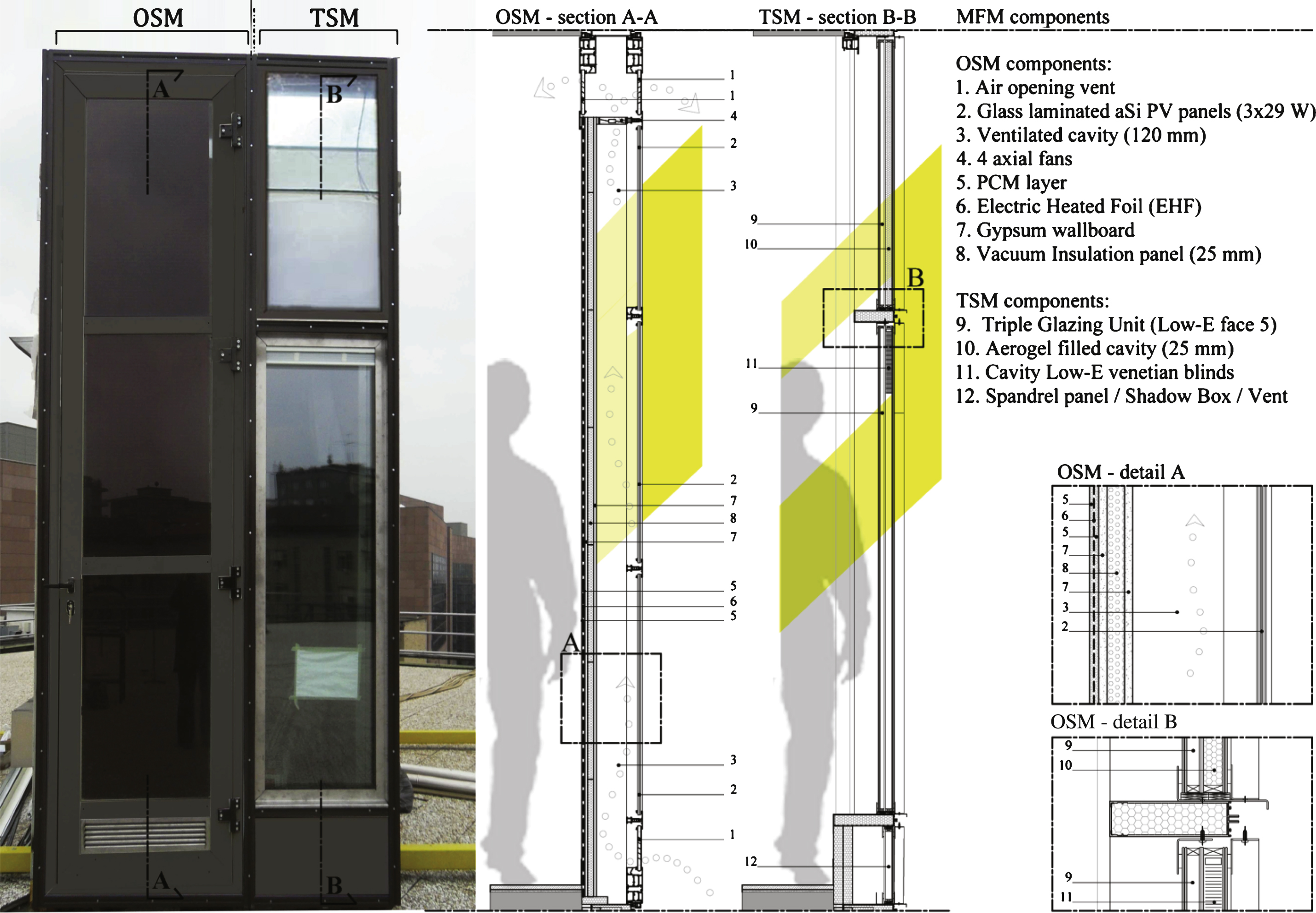
Fig.2
ACTRESS operating modes (summer and winter day, summer and winter night).
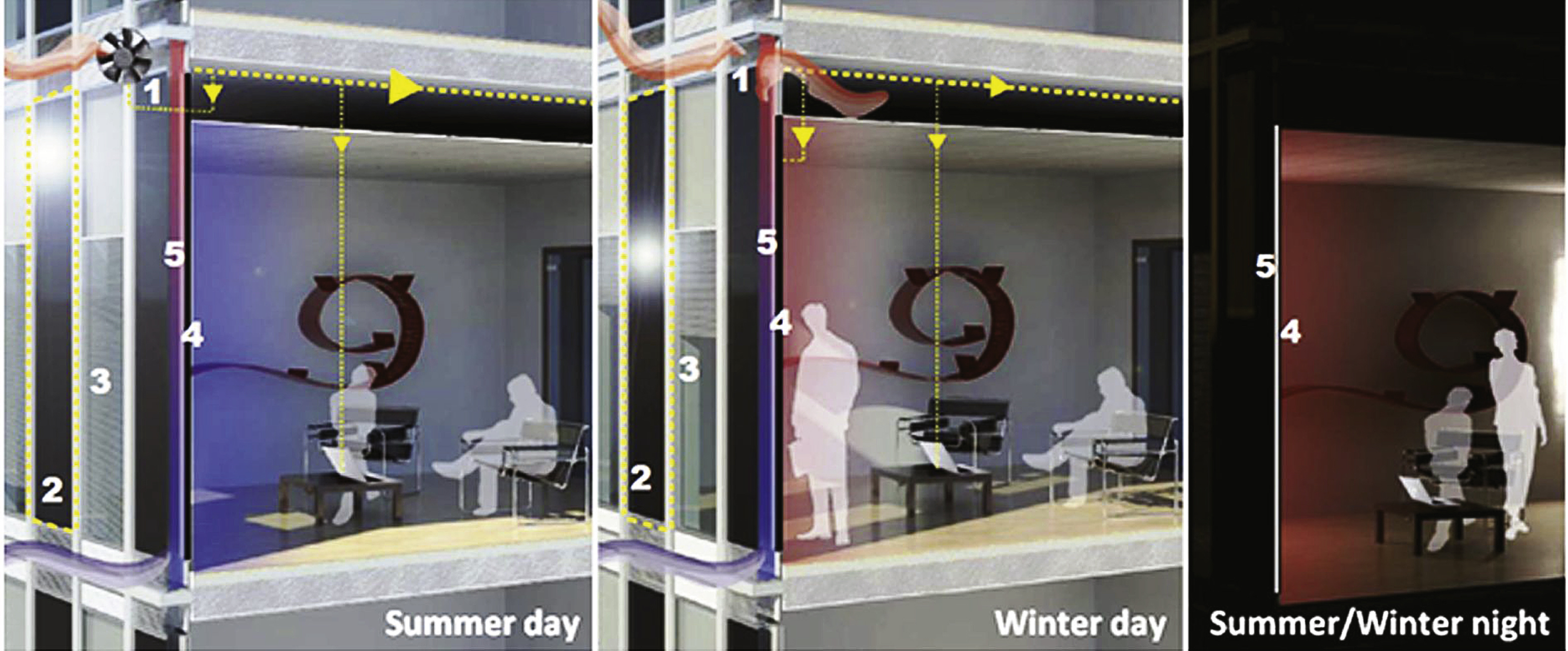
Fig.3
ACTRESS MFM components and modeling flow-chart.
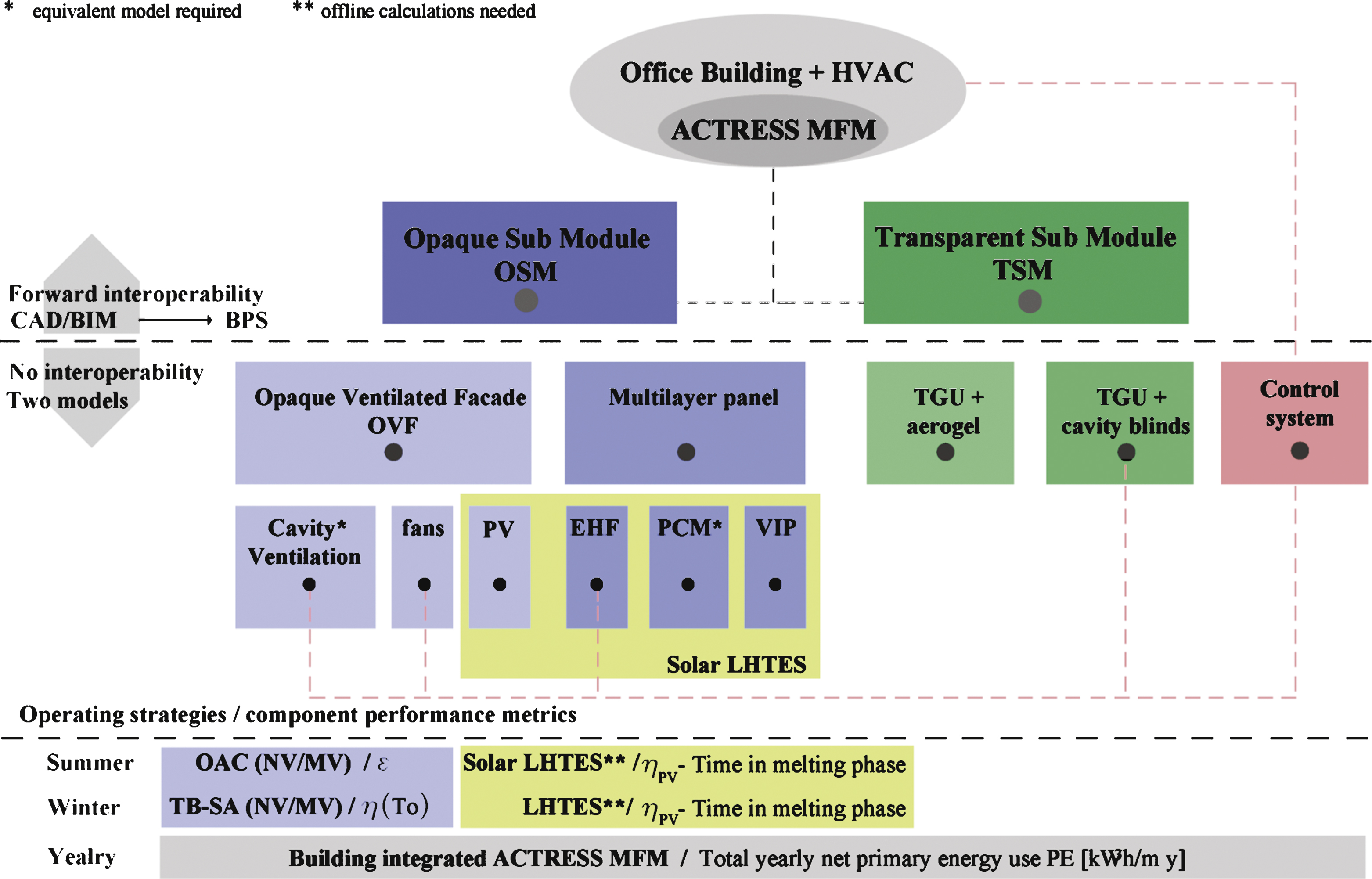
Fig.4
PCM fictitious cavity heating (red) and cooling (blue) loads in the hottest week of the year.
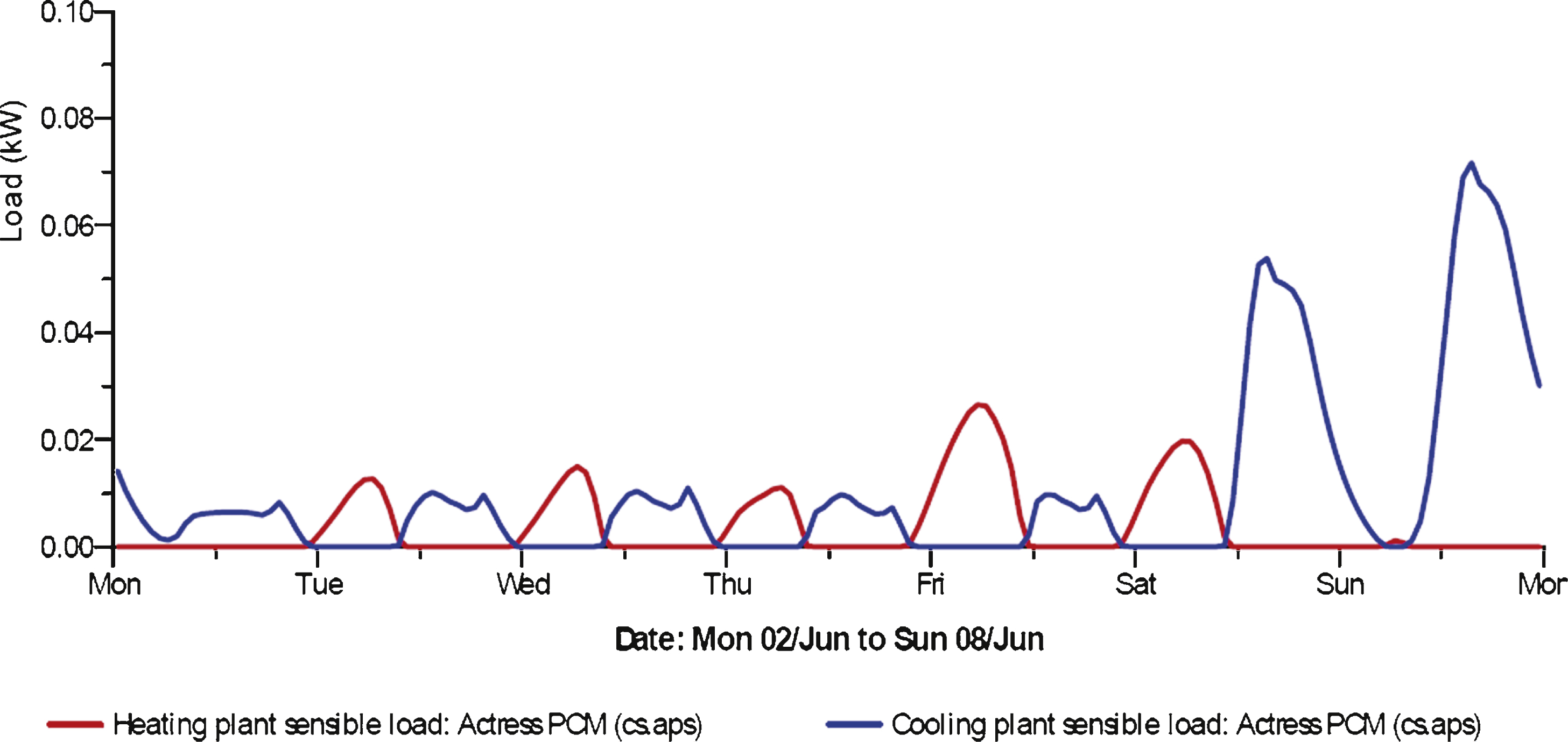
Fig.5
Simulated office test rooms.
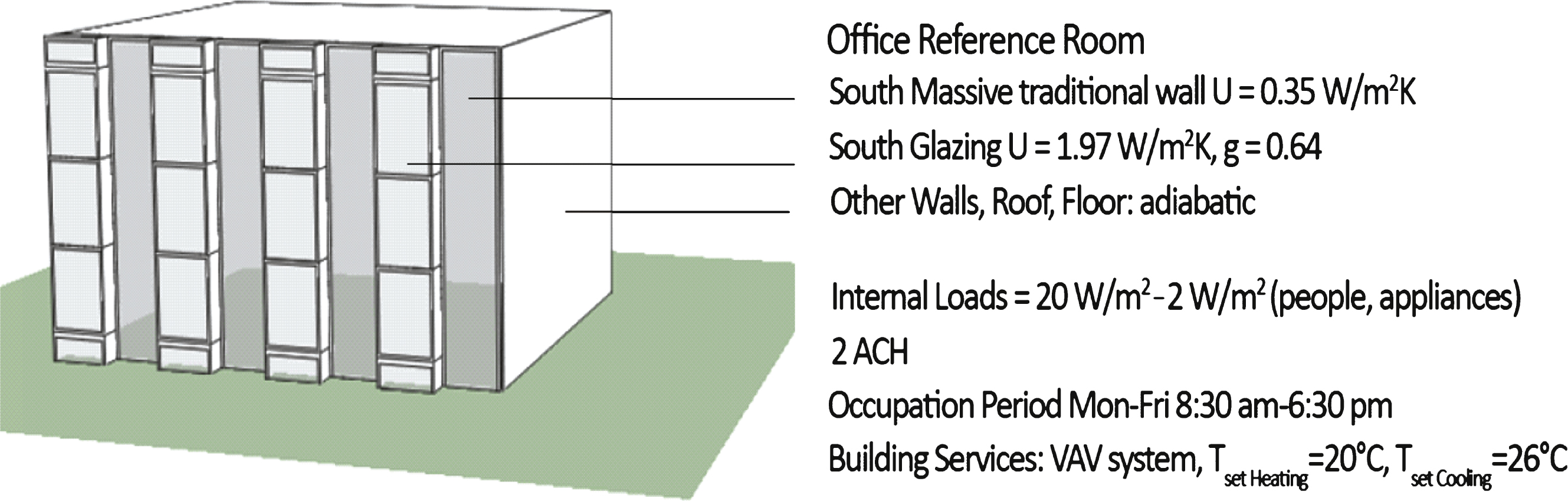
Fig.6
OSM Cavity exhaust air temperature: MV (blue), NV (red) and no ventilation (green).
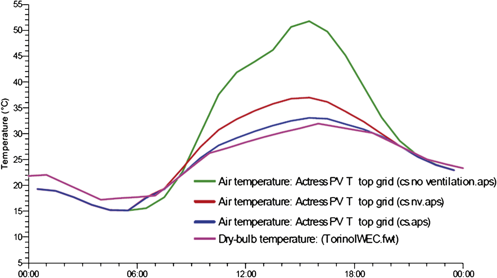
Fig.7
Improved PV efficiency due to rear ventilation.
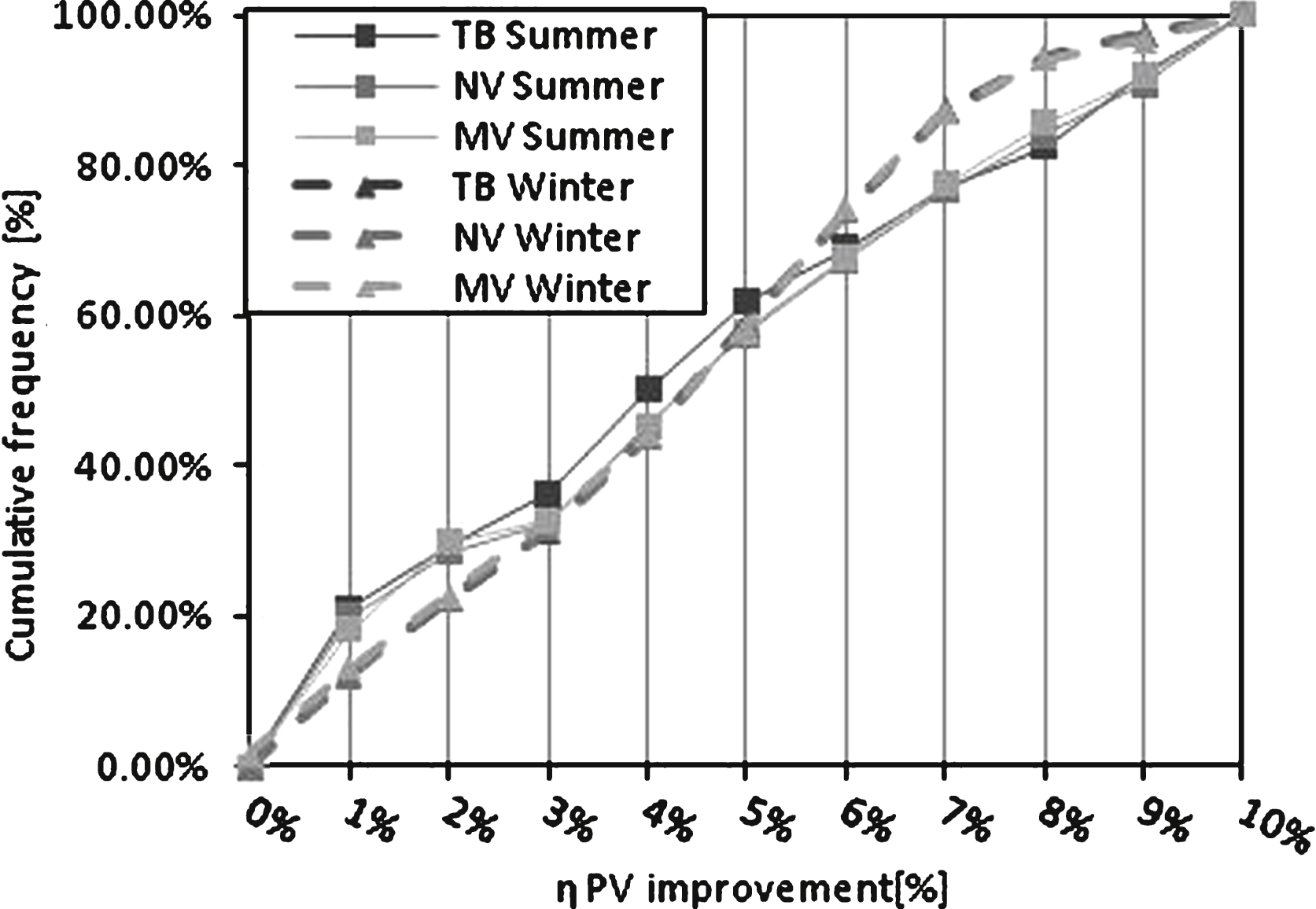
Fig.8
Cumulated frequency of dynamic insulation efficiency.
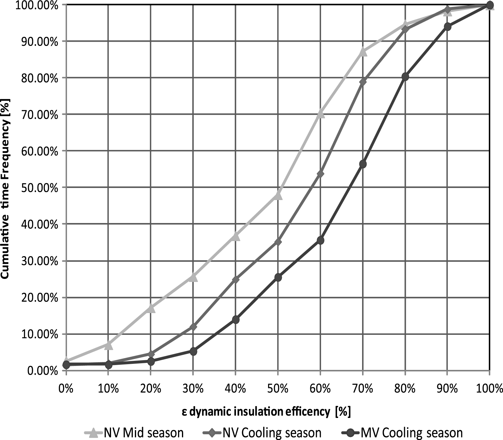
Fig.9
Cumulated frequency analysis of preheating efficiency during the heating season.
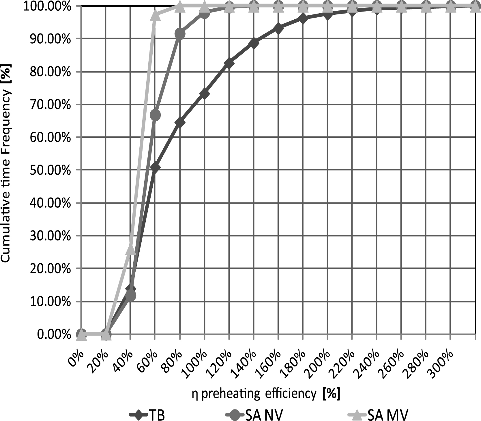
Fig.10
Cumulated frequency analysis of preheating efficiency during the mid season.
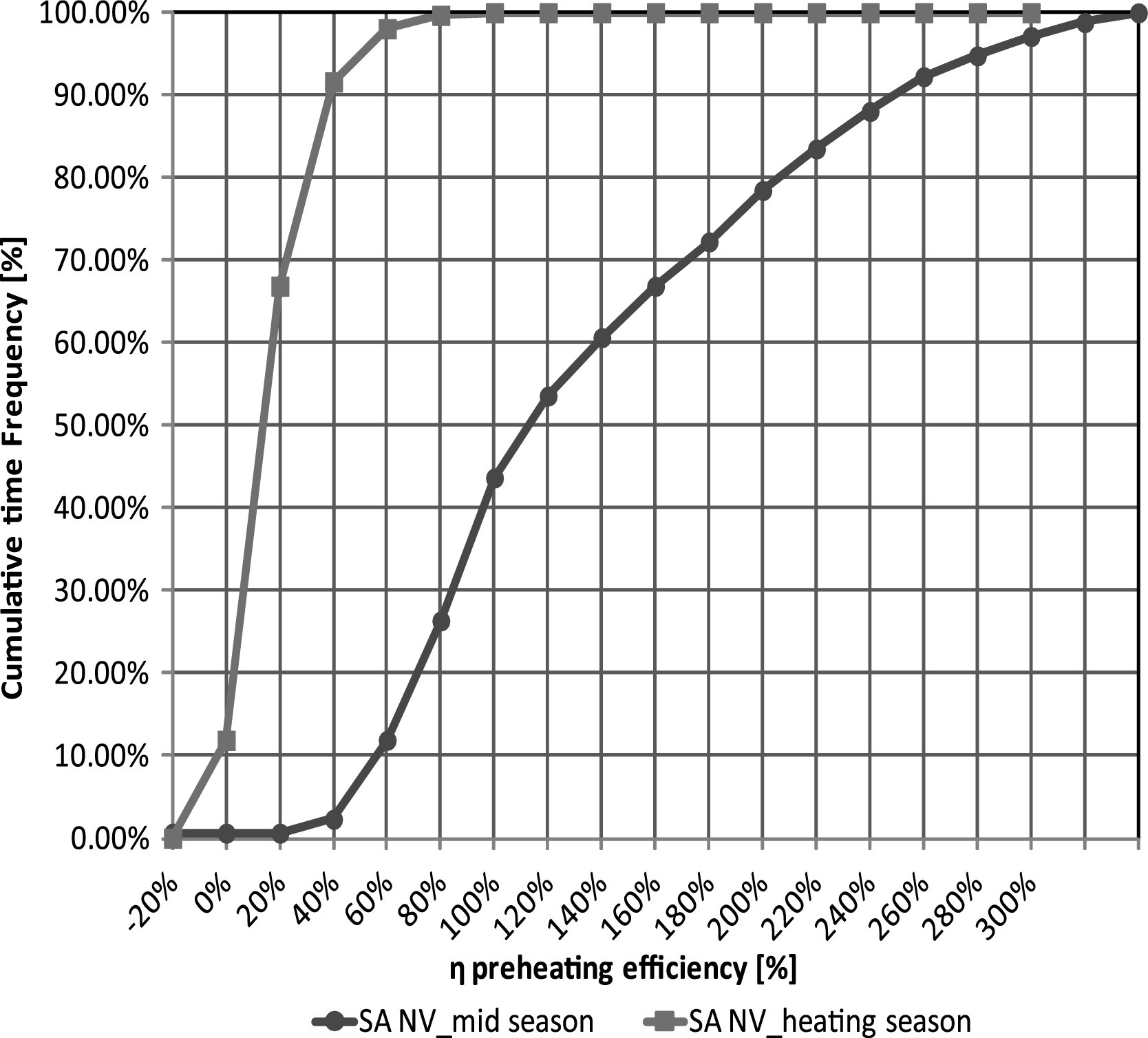
Fig.11
Time percentage in which the PCM is within the melting range (cooling season).
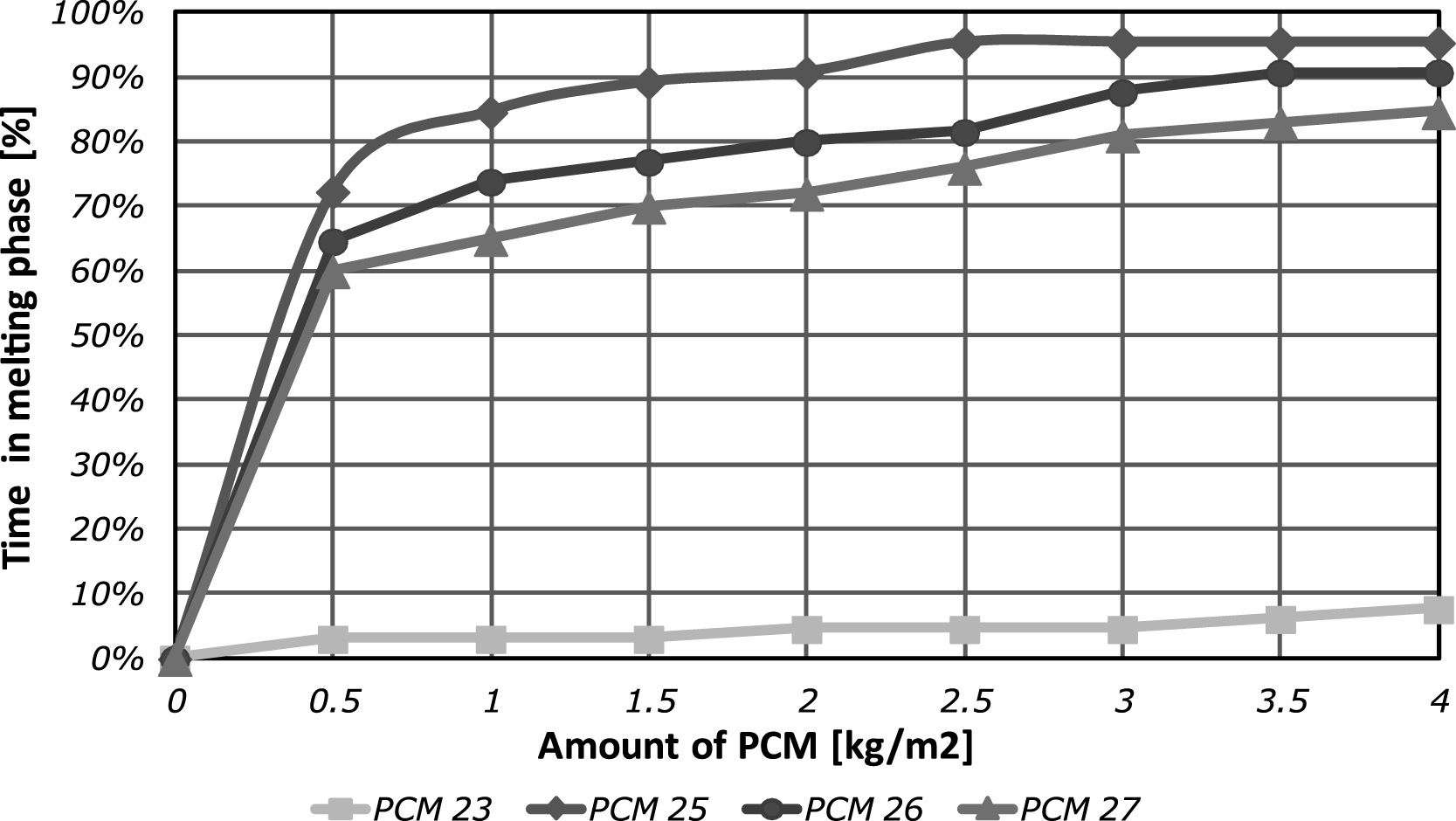
Fig.12
Time percentage in which the TPCM = 25 °C PCM is within the melting range.
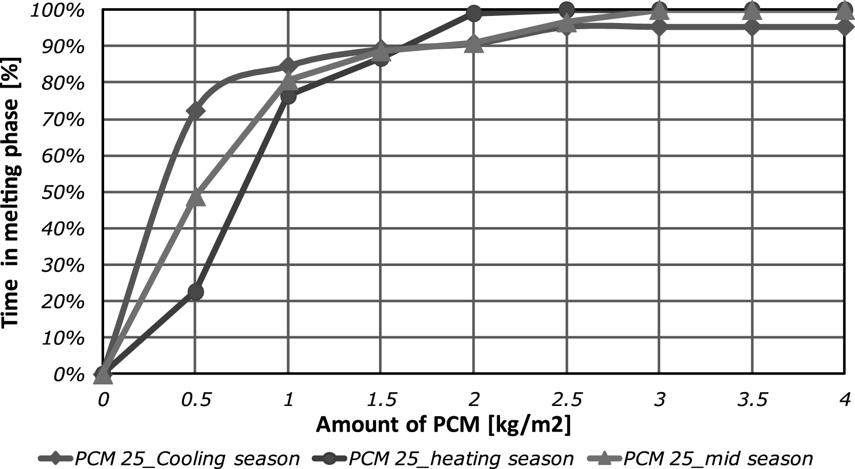
Fig.13
Percentage of the energy produced by the PV panel that is stored in the PCM layer.
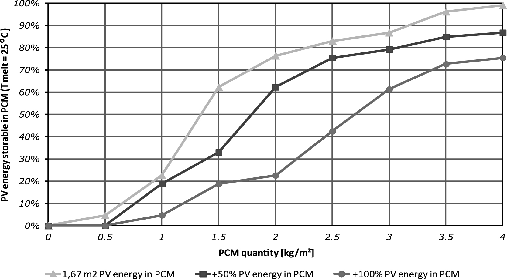
Fig.14
Break up and total specific Primary Energy consumption of the office room with the different facade options.