
Composite UHPC-AAC/CLC facade elements with modified interior plaster for new buildings and refurbishment. Materials and production technology
Abstract
The awareness of the environmental impact of the building sector is increasing. Steel reinforced concrete is the most commonly used construction material, though with a high-embodied energy and carbon footprint. Large environmental gains may arise if an alternative to steel reinforced concrete is developed. In this context, ultra-high performance concrete (UHPC) materials are shown to be promising alternatives with advantages such as lower embodied energy and reduced environmental impact. Predictions suggest that UHPC composite elements for building envelopes could have other benefits such as an increased service life, optimised use of building area due to thinner elements and minimised maintenance due to the absence of reinforcement or use of non-corrosive reinforcing materials such as carbon fibres. In the framework of the H-HOUSE project funded by the European Commission, composite elements are developed. The aim is to create facade panels combining an autoclaved aerated concrete or cellular lightweight concrete insulation layer with an external UHPC supporting layer. To enhance occupant comfort and health, hygroscopic materials that are capable to buffer indoor air humidity shall be applied to the inside of such elements. Indoor air humidity levels are expected to be more stable, which shall subsequently improve the indoor climate and minimise potential decay to the construction.
1Introduction
The purpose of an adequate building envelope is protection against moisture ingress, heat loss in winter, excessive heating in summer and noise. Components for the interior should be able to buffer heat and humidity peaks and prevent pollutants and noise. Solutions for both components for building envelope and components for the interior have to be durable, energy-efficient and affordable. In this framework the development of prototype facade elements comprising hygrothermally treated ultra-high performance concrete (UHPC) in combination with autoclaved aerated concrete (AAC) or cellular lightweight concrete (CLC) are presented. To improve the indoor environment quality with regards to balanced indoor air humidity levels, an earth plaster modified with aerogel, demonstrating an increased moisture buffer, was developed. UHPC exhibits extreme high strength and excellent chemical durability. The exceptional properties of UHPC are the result of a high packing density based on an optimised particle size distribution and significant reduction of water in the cement paste compared to ordinary concrete (Larrard & Sedran, 1994). The workability of UHPC is adjusted by adding highly efficient plasticisers, obtaining mixes capable to flow or even with self-compacting properties. The very high density of the material is of course beneficial to its durability. Numerous studies showed that due to the limited adsorption of moisture and negligible moisture transport the resistance of UHPC against any kind of deterioration mechanism is drastically increased compared to normal concrete. In the case of building envelopes the excellent resistance against freeze-thaw attack and penetration of chloride ions in marine environments is a particular advantage (Ahlborn et al., 2008; Thomas et al., 2012; Piérard et al., 2012). UHPC was already applied successfully to building constructions, such as lightweight roof constructions, facade elements (Acker & Behloul, 2004; Behloul & Batoz, 2008; Rebentrost & Wight, 2008a; Szolyd, 2014) and protection panels (Rebentrost & Wight, 2008b). In this study, lightweight AAC with a dry density between 100 to 115 kg/m3 was employed. This material provides a low thermal conductivity in combination with mechanical properties adequate for the use as insulation layer in composite elements (ETA, 2011).
The use of CLC in residential building applications has been limited, so far, to social housing projects where a large number of units needs to be constructed in a short period; at densities of around 600 kg/m3 CLC constitutes an affordable and sustainable alternative providing both structural and insulation characteristics. In this study the typology of a half-panel element was developed. The typology is non-load bearing and it was conceived to be used for new buildings and for renovation of existing buildings. Small-scale half elements were developed to assess the feasibility of the production technology process.
2Facade element components
The general idea is to realise the external UHPC shell as a box-shaped element (Fig. 1). Due to the support from the edges of the box no shear forces are generated in the UHPC-AAC/CLC interface during transport and service life. Thus, no additional connectors are necessary, provided that the bond between UHPC and AAC/CLC is sufficiently high to prevent from detachment of the layers when the composite element is tilted after demoulding and during transport. Moreover, the edges are forming a frame and improve the stiffness of the box-shaped element, allowing the decrease of the thickness of the exterior UHPC layer. In the corners, the cross section of the frame is broadened to include the assemblies for anchoring and transport/mounting. Figure 2 and Table 1 give an overview of the geometry of the panels. The design was based on load assumptions required by Eurocode 2 (EN 1992-1-1, 2004). In particular a wind speed of 44 m/s equivalent to a wind load of 1.66 kN/m2 was considered.
2.1UHPC
Due to the extraordinary high strength and the high density of UHPC, it is possible to produce very thin and durable facade elements. The use of UHPC for light-weight elements would reduce the environmental impact in relation to manufacturing, transport and installation processes.
The UHPC adopted is based on Dyckerhoff Nanodur® technology. Nanodur compound contains ultrafine components (Portland cement, blast furnace slag, quartz, synthetic silica) smaller than 250μm that are dry mixed intensively. In this way the homogeneity and dense packing of the particles is reliably achieved and the wet mixing process of the UHPC with a standard concrete mixer is simplified significantly (Table 2). Nanodur cement is a CEM II B-S 52.5R according to the standards (EN 197–1, 2011).
Further reduction of embodied energy was achieved by replacement of Portland cement with less energy intensive types of cement or supplementary cementitious materials (SCM) originating also from industrial residuals. In order to increase the performance of UHPC, hydrothermal curing (autoclaving) is applied, a technique used for the industrial production of AAC elements.
Solutions are referred to minimum compressive strength of 100 N/mm2 for non-load bearing applications and high quality of the formed UHPC surface.
With screening tests three superplasticizers were identified for optimum workability of the fresh UHPC. Shrinkage of the UHPC was identified as potential problem with regard to bond behaviour and large sizes of composite elements. With the use of a shrinkage-reducing admixture promising results were obtained.
2.2Insulation materials
2.2.1AAC
The material structure of AAC is characterised by a solid skeleton and aeration pores being formed during the aluminum-driven expansion of the slurry. The solid skeleton consists of hydrothermally synthesized crystalline calcium-silicate-hydrates (thereof mainly tobermorite) and, moreover, minor contributions of unreacted sand. The foam-like structure of AAC, with its solid skeleton acting as partitioning walls between the aeration pores (Alexanderson, 1979), leads to an optimum correlation between weight and compressive strength. Millions of aeration pores lead to a low thermal conductivity making AAC a highly thermal insulating building material.
Thermal conductivity depends on temperature, density, structure and chemical nature of the material. In AAC, it is largely a function of density and moisture content (Narayanan & Ramamurthy, 2000; Oel, 1980; Lippe, 1986).
For this reason, improvements of the thermal performance of AAC had been mainly achieved by reducing the dry density (Fig. 3a). Although the strength of the remaining solid skeleton could be steadily improved in the last decades, decreasing the dry density by trend leads to losses in the compressive strength (Fig. 3b). In other words, the material properties of AAC always represent a compromise of mechanical and thermal properties. In case of a certain minimum mechanical requirement, options for reducing the thermal conductivity are limited. For AAC, the lowest range of lambda-values (declared thermal conductivities = 42 to 47 mW/(m·K) (ETA, 2011; EN ISO 10456, 2010) was accomplished at dry densities between 85 and 115 kg/m3. Due to its extremely low mass, such light-weight AAC is a pure insulation material without any load bearing capacity (see Table 3). The difference is only the dry density, being achieved by altering the amount of aluminum (the more aluminum the lower the dry density).
2.2.2CLC
In order to be used as a high performance insulation material, very low density CLC must be developed; the goal is to achieve a thermal conductivity of 30–35 mW/(m·K) at a density around 150 kg/m3. Given the high volume of foam, the main challenge is to guarantee that the cementitious matrix sets fast enough to sustain the porous structure without collapse of the foam. For this purpose, calcium aluminate cement was chosen as binder, which sets much faster when compared to Portland cement. Table 4 lists the range of mix compositions tested and respective target and obtained densities. Initial tests had as objective to evaluate the compressive strength and thermal conductivity of a series of samples to be used as a benchmark for further development.
The results in Fig. 4a show that, at low densities, very low values of compressive strength are obtained; in addition, the scatter is also large. This is typical for CLC in which the mechanical properties are very much dependent on the homogeneity of the air void distribution.
The results from thermal conductivity measurements (Fig. 4b) are quite promising; at a density about 300 kg/m3, the λ-value is around 70 mW/(m·K). Given the good linear correlation with density, a λ-value below 45 mW/(m·K) can be expected for the target density of the research.
2.3Modified earth plaster
To increase the moisture buffer capacity of clay minerals, earth plasters will be modified with aerogels. Due to the highly porous structure of the aerogels, it is important to optimise the water addition to maintain workability of the material mixture and to reduce drying shrinkage. Aerogels were therefore customised with regards to their size, porous structure as well as their densities. Furthermore, fibres were added to certain material mixtures, which increase the allowance for drying shrinkage of the base material. Different mixing methodologies have also been applied and evaluated.
Two different types of Quartzene® were used in the form of granules (GI) or powder (PI), denoted CMS and ND. CMS is composed of hydrated calcium magnesium silicate, whereas the other one consists of pure hydrated silicon dioxide (ND). Five different earth plasters were used: earth plaster - base coat (EPB), earth plaster - mineral 16 (M16), earth plaster - rough - final coat (EPRF), earth plaster - rough - final coat - fine (EPRF fine) and earth plaster - fine - final coat (EPFF).
Results demonstrate a very large scatter with regards to drying shrinkage (Table 5).
Although it was aimed to keep the water addition low, some material mixtures demonstrated an inacceptable level of shrinkage. Through the incorporation of fibres, shrinkage values could be significantly improved. In addition to drying shrinkage, strength properties of the developed materials have been conducted to verify an acceptable material performance with regards to fitness for purpose (Table 5).
Although a number of material mixtures have passed all tests, the results demonstrated that the use of aerogel in combination with earth plasters is sensitive to failures. Replicability of tests has proved to be difficult and results from test series show a relatively large scatter, even though sample production and testing were conducted in exactly the same way. In addition, certain tests with different material mixtures provided unexpected and in certain cases contradicting results.
3Energetic and hygrothermal performances
Following the targets of the European Commission related to the primary energy demand for buildings by 31st December 2020 all new constructions shall be nearly zero-energy buildings (NZEB). In this framework the goal of facade elements here proposed is therefore to achieve or undercut a U-value of 0.15 W/(m2·K).
A first assessment of the thermal behaviour of the composites elements was carried out considering the physical and thermal properties reported in Table 6. These properties are expected values that are assumed to be reached with a high certainty. Further improvements are expected with the incorporation of aerogels, in particular for the thermal conductivity. In the current configuration the half panel present a U-value of 0.140 W/(m2·K) for AAC and 0.142 W/(m2·K) for CLC.
To minimise the energy consumption of a building further, the UHPC concrete composite elements are designed to be highly airtight. It is therefore suggested to apply modified earth plasters to the inside of these panels. The developed earthen plaster materials are expected to demonstrate an increased water vapour adsorption capacity, and are hence able to balance indoor air humidity levels and to provide healthy and comfortable spaces for occupants. Modified earth plasters as well as base materials have been tested with regards to their hygrothermal performance. The moisture buffer capacity of the developed materials was assessed via water vapour adsorption tests according to the standards (DIN 18947, 2013). Water vapour adsorption classes for earth plasters, set out in DIN 18947, are incorporated in the results. Findings demonstrate the positive material performance of the developed materials (Fig. 5).
The modified base coat plaster adsorbs nearly 100% more water vapour than the pure material, whereas the modified final earth plaster, applied on top of the modified base coat plaster adsorbs approximately 50% more than the pure earth plaster (after 12 hours). However, it is surprising that the latter material mixture adsorbs 2/3 less than the modified base coat plaster, although both original materials adsorb almost the same amount of water vapour. During the mixing process it has been observed that the aerogel material influenced the formation of the surface. Fine material particles became visible at the sample surface, which seemed to make the surface denser.
4Production technology of composite UHPC-AAC/CLC
4.1Manufacturing of UHPC boxes
The purpose of this section is to present the product technology used for producing UHPC-AAC composite elements. First trials were dedicated to the one-step production of the box-shaped UHPC elements, i.e. the exterior UHPC layer and the upturning edges are cast with a single concrete batch. For this purpose a ‘floating body’ was adopted. The protection of the floating body against buoying upwards requires accurate measures when full hydrostatic pressure is considered. In the case of full-scale elements, where the buoyancy may reach high values, it might be too complex to accurately fix the floating bodies. Therefore, in a second approach, further trials were dedicated to a two-step production procedure of the UHPC box with the upturning edges of the box being cast on top of the exterior layer after initial hardening (Fig. 6).
In the tests a Multipor® block was used as internal formwork. One day after the cast of the exterior layer the Multipor® block was placed on its top without fixation and the upturning edges were cast. The UHPC was poured into the gap between formwork and Multipor® block at one corner of the formwork. The UHPC was easily flowing around the Multipor® block filling the gap completely without generating any buoyancy; i.e. during the cast the Multipor® block was simply held in place manually and the UHPC was not penetrating under the Multipor® block, even though the backside of the exterior layer was not perfectly smooth.
Due to the two-step manufacturing procedure the UHPC boxes cannot be regarded as monolithic, like in the case of the one-step manufacturing. In fact, a distinct layering was observed, visible as a joint between exterior UHPC layer and upturning edges (Fig. 7). In order to evaluate the bond strength between the two UHPC layers, preliminary shear and pull-off tests were performed.
It is supposed that ‘gluing’ of Multipor® blocks on the back side of the exterior UHPC layer with a rapidly hardening mineral-based adhesive with low shrinkage will ease the cast of the upturning edges, and thus the production of full-scale elements. On the other hand, when UHPC boxes are needed as ‘moulds’ for the cast of fresh AAC and subsequent joint autoclaving, a rigid frame as internal formwork on top of the exterior UHPC layer is supposed to be more efficient for the cast of the upturning edges than a block. A frame consisting of several parts will be more flexible and easier to install as well as to remove when the element is demoulded after hardening of the UHPC.
4.2Manufacturing of insulation
Small-scale box-shaped UHPC elements as shown in Fig. 8a were prefabricated at Dyckerhoff laboratories and were shipped to Xella and CBI for the manufacturing of half panels using AAC and CLC respectively. After sufficient hardening of the UHPC, the developed AAC/CLC are cast directly on these panels to realise the insulation layer of the small-scale element.
In the case of AAC the UHPC boxes were filled with fresh slurries so that the swelling process induced by the reaction of the aluminum and the set of the AAC occurred inside the UHPC boxes (Fig. 8b, c).
After 24 hours the elements were autoclaved. After autoclaving two AAC composites samples revealed severe crack formation, presumably as a consequence of differences in thermal strain between the AAC insulation layer and the encasing UHPC box. The observed results suggest that the pursued strategy of manufacturing UHPC/AAC half panels is not suitable for AAC with dry densities ≥175 kg/m3.
It is assumed that the observed cracks both in the AAC and in the UHPC box are a consequence of a restrained thermal dilation of the material in particular during the cooling phase of the autoclaving process, resulting in tensile stresses.
Concerning the manufacturing of CLC there are, however, two main aspects that need to be considered: thorough wetting of the internal surfaces of the UHPC before casting to avoid CLC collapse and decrease shrinkage; and after casting, enough time should be given in order to allow the CLC to dry and thus avoid excessive moisture to be entrapped in the insulation.
So far, small-scale samples (Fig. 9) were prepared using CLC with a density about 300 kg/m3. After hardening, the CLC generally maintained its original dimensions. Mainly around the edges, cracking and detachment of the CLC from the UHPC was observed but without compromising the integrity of the panel.
5Conclusions
The box-shaped concept is a simple and robust solution for the facade elements; besides the good structural performance, the concept enables efficient protection of the insulation material during transport, installation and use. Additionally, due to the absence of reinforcement and connectors through the insulation, the production technology does not involve major labour-intensive tasks, which is desirable for scale-up.
The preliminary studies showed more advantages of a two-step manufacturing procedure of the UHPC boxes than a one-step procedure. In this framework the bond between UHPC layers plays a key role with the production of non-monolithic UHPC elements. The bond strength between the UHPC substrate and the UHPC top layer was evaluated by shear tests and pull-off tests with promising results. However, future activities need to include more systematic investigations, in particular with regard to the surface properties of the UHPC substrate.
In the manufacturing of small-scale UHPC-AAC composite elements a satisfying bond between the UHPC and the AAC was observed. However, the investigations of the thermal deformation behaviour of the composite elements will be part of future activities.
A possible optimisation of production technologies will cover both two-step manufacturing of UHPC boxes and ‘gluing’ of AAC blocks on hardened UHPC. The one-step manufacturing of full-scale UHPC boxes appears too complex and will not be investigated further.
Before casting the insulation layer, thorough wetting of the UHPC substrate is recommended to avoid collapse and harmful shrinkage of the CLC. Special attention has to be paid to the drying of the CLC to avoid excessive moisture entrapped in the insulation layer after mounting of the facade elements.
The hardening process of CLC seems compatible with panel configuration. The CLC generally maintained its original dimensions. Only around the edges, minor cracking and detachment were observed without compromising the integrity of the panel. Future activities will include quantification of the bond strength of the UHPC-CLC interface. Future work will focus on the incorporation of fibres and aerogels. The first is expected to contribute to an increase in the mechanical stability of the CLC whilst the second will considerably lower the thermal conductivity to values in the range of 30–35 mW/(m·K).
The use of an earth plaster modified with aerogel seems a promising way to improve indoor hygrothermal conditions. The material development to date indicates that aerogels increase the water vapour adsorption capacity of an earth plaster by approximately 70–90% . The next steps shall investigate, if the water vapour adsorption process is restricted through the modified surface of the earth plaster. In addition, adhesive strength and abrasion tests will be conducted. Furthermore, the optimisation of the material mixtures shall be progressed to enable the development of a marketable product.
Acknowledgments
This research study was made possible with the support of the European Union’s Seventh Framework Programme for research, technological development and demonstration under grant agreement no. 608893 (H-House, www.h-house-project.eu).
Reference
1 | Acker, P. & Behloul, M. (2004). Ductal® technology: A large spectrum of properties, a wide range of applications. In: Proc. Int. Symp. On Ultra High Performance Concrete, September 13-15, 2004, Kassel, Germany, 11-23. |
2 | Ahlborn, T. M., Misson, D. L., Peuse, E. J., & Gilbertson, C. G. (2008). Durability and Strength Characterization of Ultra-High Performance Concrete under variable Curing Regimes. In: Proc. 2nd Int. Symp. on Ultra High Performance Concrete, Fehling, E., Schmidt, M., & Stürwald, S. (Eds.) Kassel, Germany, March 5–7, 2008, Schriftenreihe Baustoffe und Massivbau (10), Kassel University Press, 197–204. |
3 | Alexanderson J(1979) Relations between structure and mechanical properties of autoclaved aerated concreteCem Concr Res9: 4507514 |
4 | Behloul, M., & Batoz, J. -F. (2008). Ductalü applications over the last Olympiad. In: Proc. 2nd Int. Symp. on Ultra High Performance Concrete, Kassel, Germany, March 5–7, 2008, Schriftenreihe Baustoffe und Massivbau (10), Kassel University Press, 855–862. |
5 | Bus Center RATP in Thiais, France (www.szolyd.com). |
6 | De Larrard F, Sedran T(1994) Optimization of ultra-high-performance concrete by the use of a packing modelCement and Concrete Research24: 9971009 |
7 | DIN 18947 (2013). Earth Plasters – Terms and definitions, requirements, test methods. |
8 | EN ISO 10456 (2010), Building materials and products – Procedures for determining declared and design thermal values. |
9 | EN 1992-1-1 (2004). Eurocode 2: Design of concrete structures – Part 1-1 – Part 3. |
10 | EN 197-1 (2011). Cement. Composition, specifications and conformity criteria for common cements. |
11 | European Technical Approval, ETA-05/0093 (2011). Multipor thermal insulation panel, valid to June 1, 2019. |
12 | Lippe, K. L. (1986). Entwicklung hochporöser C-S-H- Werkstoffe mit minimaler Wärmeleitfähigkeit. BMFT Forschung Band 86, Fachinformationszentrum Energie/Physik/Mathematik |
13 | Narayanan N, Ramamurthy K(2000) Structure and properties of aerated concrete: A reviewCement & Concrete Composites22: 321329 |
14 | Oel, H. J. (1980). Wärmeleitfähigkeit und Festigkeit von Calzium-Hydrosilicat-Produkten. Abschlußbericht DFG Forschungsvorhaben Mo 256/6. |
15 | Piérard, J., Dooms, B., & Cauberg, N. (2012). Evaluation of Durability Parameters of UHPC Using Accelerated Lab Tests. In: Schmidt, M. et al. (Eds.): Proc. of Hipermat 2012, 3rd Int. Symp. On UHPC and Nanotechnology for High Performance Construction Materials, March 7-9, 2012, Kassel, Germany, 371-376. |
16 | Rebentrost, M., & Wight, G. (2008a). Experiences and applications on Ultra-high Performance Concrete in Asia. In: Proc. 2nd Int. Symp. On Ultra High Performance Concrete, Fehling, E., Schmidt, M. and Stürwald, S. (Eds.), Kassel, Germany, March 5-7, 2008, Schriftenreihe Baustoffe und Massivbau (10), Kassel University Press, 19-30. |
17 | Rebentrost, M. & Wight, G. (2008b). Behaviour and Resistance of Ultra High Performance Concrete to Blast Effects. In: Proc. 2nd Int. Symp. On Ultra High Performance Concrete, Kassel, Germany, March 5-7, 2008, 735-742. |
18 | Thomas, M., Green, B., O’Neal, E., Perry, V., Hayman, S., & Hossack, A. (2012). Marine performance of UHPC at Treat Island. In: Schmidt, M. et al. (eds.): Proc. of Hipermat 2012, 3rd Int. Symp. On UHPC and Nanotechnology for High Performance Construction Materials, March 7-9, 2012, Kassel, Germany, 365-370. |
Figures and Tables
Fig.1
Examples of the UHPC fibre-reinforced cladding in a curtain wall (Szolyd, 2014).
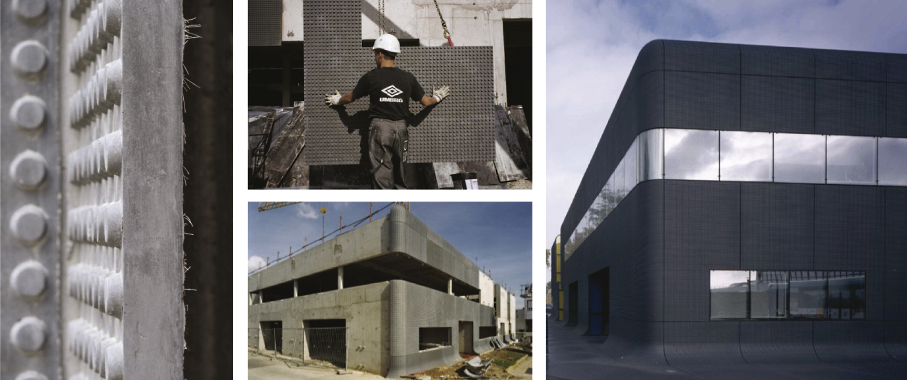
Fig.2
Half panel, non-load bearing: 5 m × 3 m. (a) Axonometric view; (b) vertical section (mid of the panel); (c) lateral view.
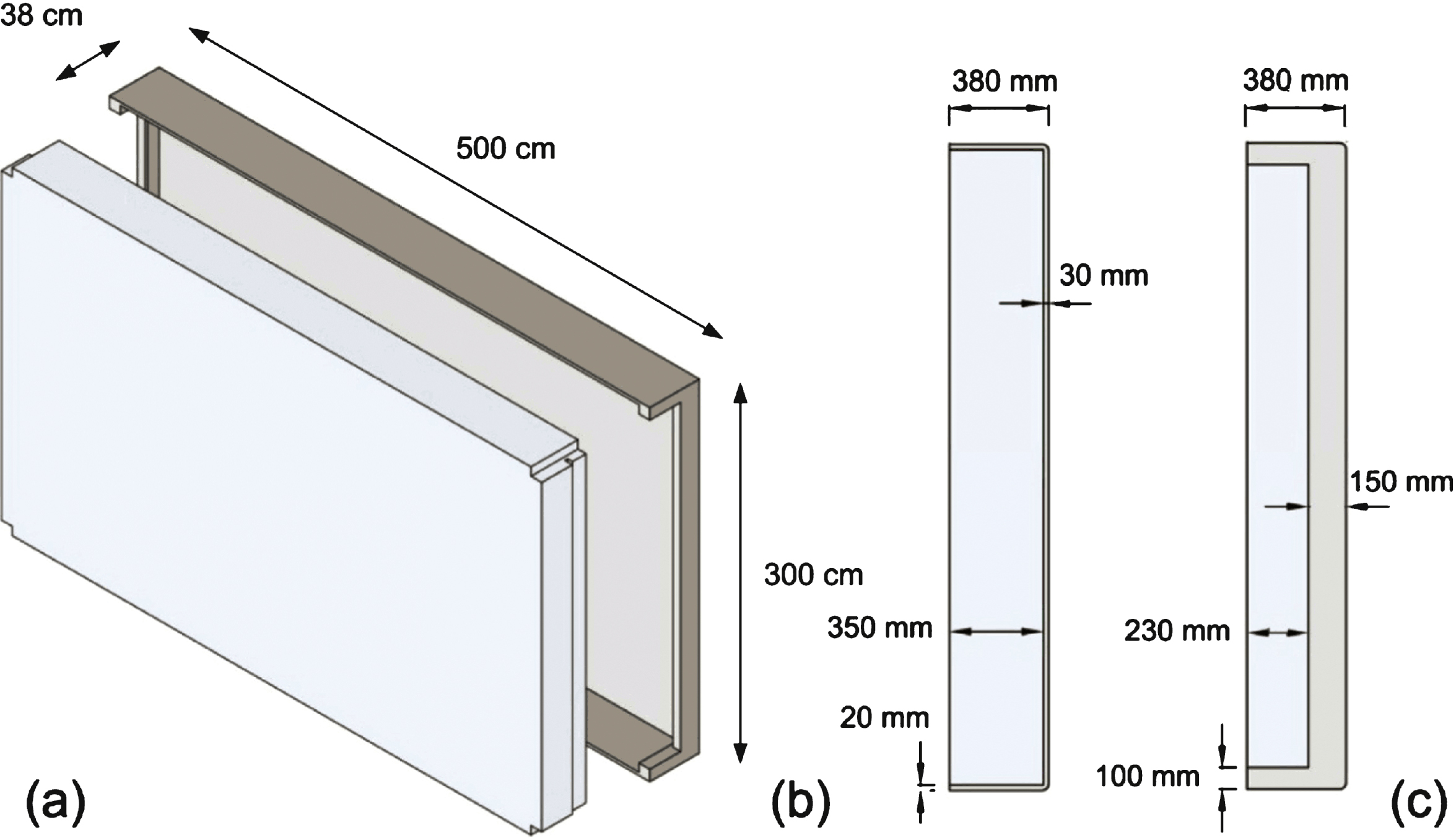
Fig.3
Correlation between AAC dry density and: thermal conductivity (a); compressive strength (b).
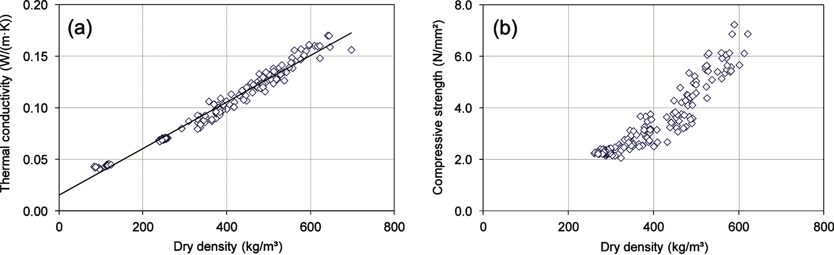
Fig.4
Correlation between CLC dry density and: thermal conductivity (a); compressive strength (b).
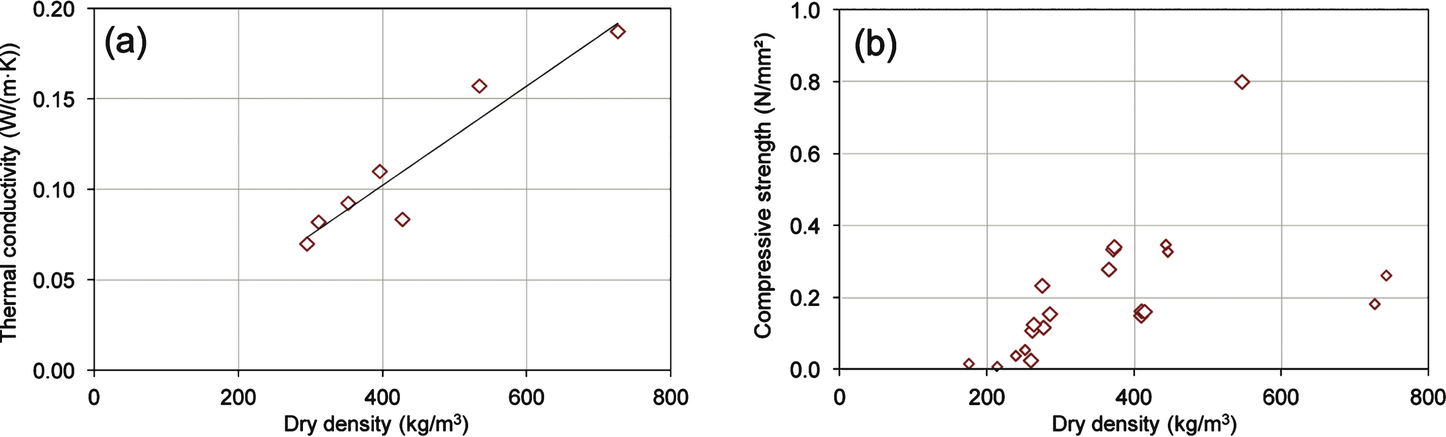
Fig.5
Results water vapour adsorption test for modified and base earth plasters. Lines WS I, II and III represent water vapour adsorption classes according to the standards (DIN 18947, 2013).
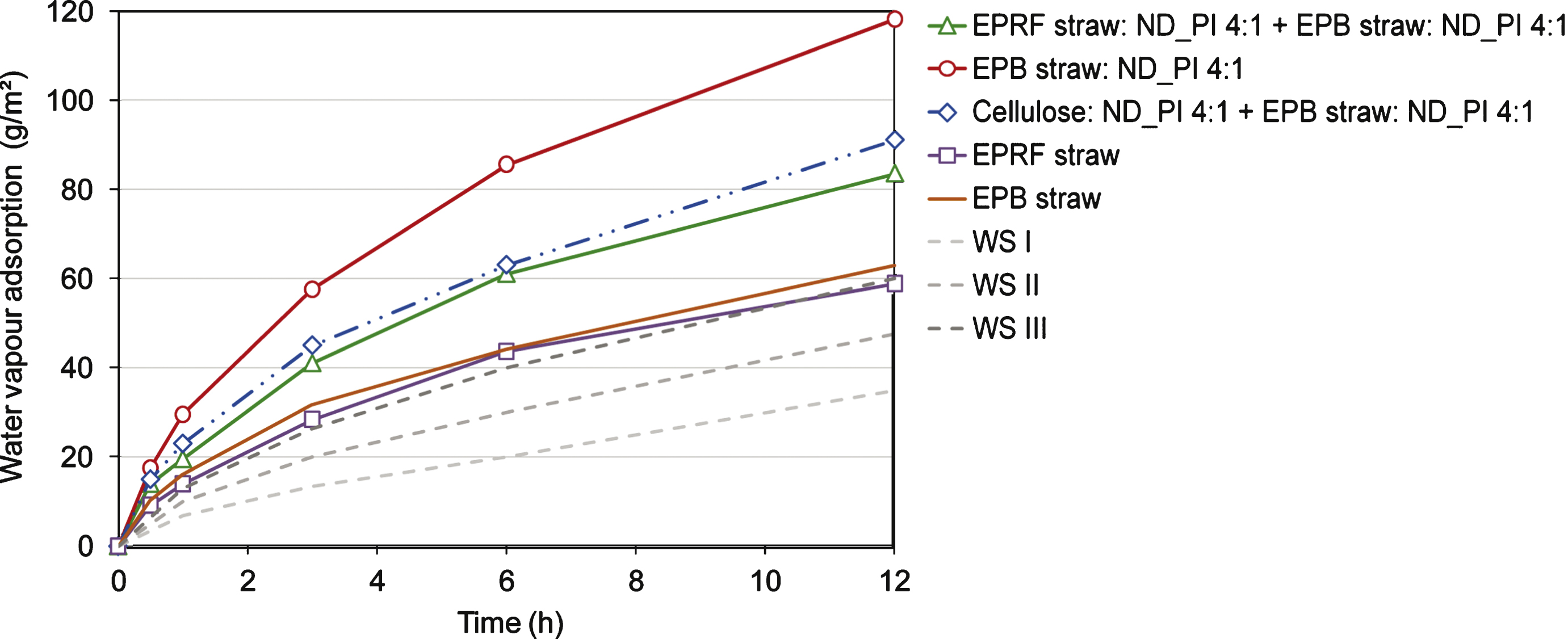
Fig.6
Procedure for two-step production of box-shaped UHPC elements. (a) Cast of exterior layer. (b) Placement of a rigid frame or a block as internal formwork on hardened exterior layer. (c) Cast of upturning edges.
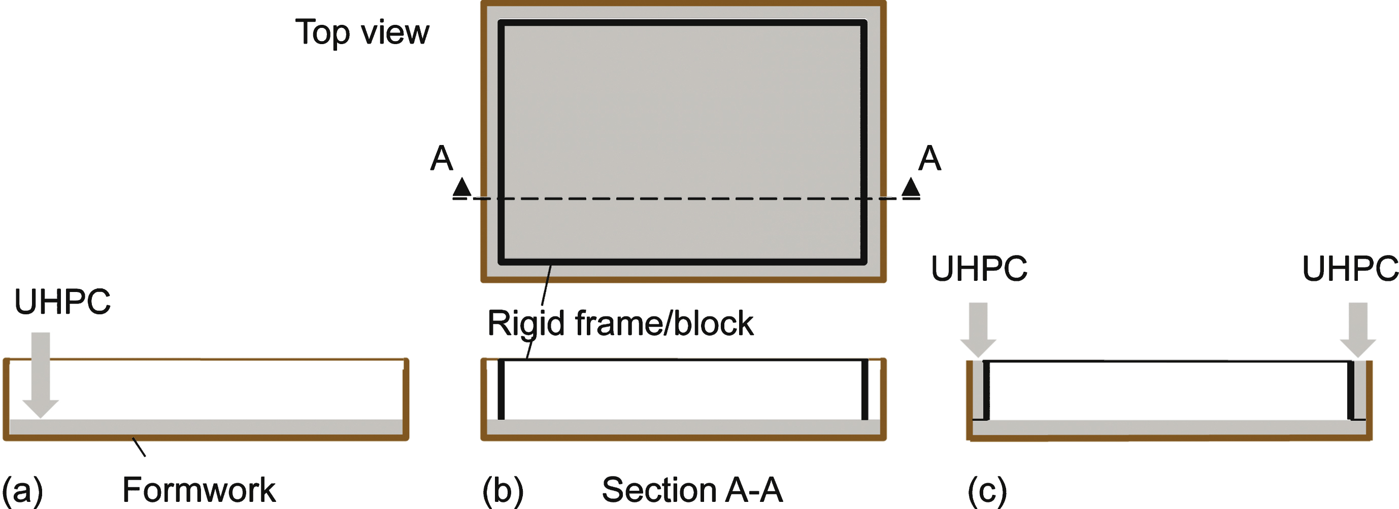
Fig.7
UHPC box manufactured with the two-step procedure: joint between exterior UHPC layer and upturning edges.
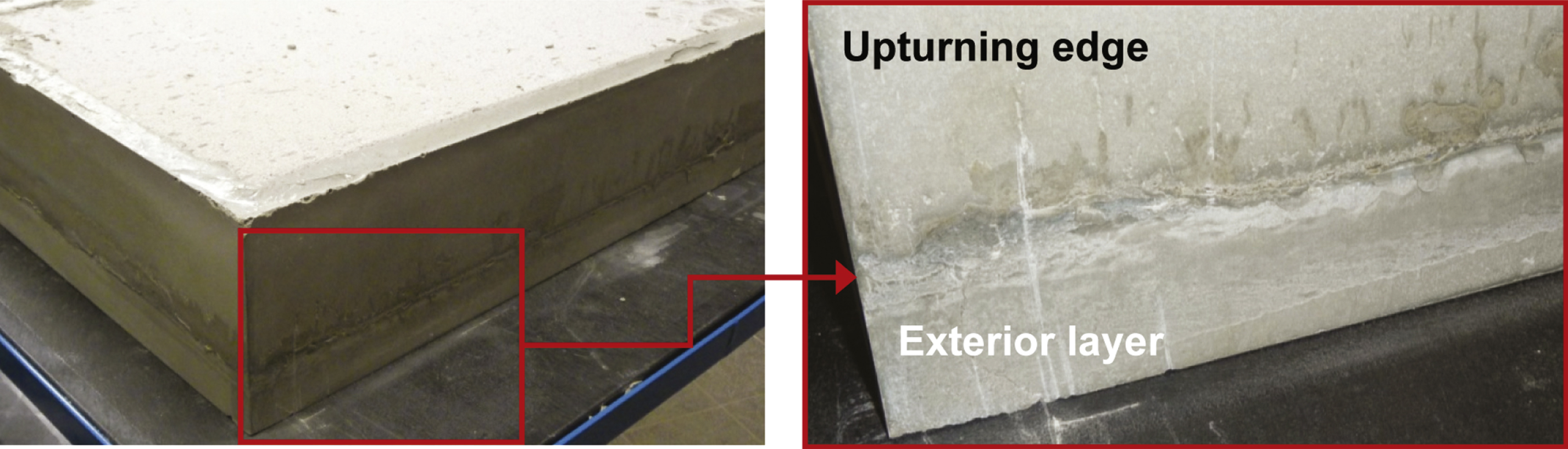
Fig.8
Manufacturing of UHPC-AAC small-scale samples. (a) Empty UHPC box with highly porous internal surface. (b) Cast of AAC slurry. (c) Swelling process of the AAC slurry driven by the aluminum reaction.
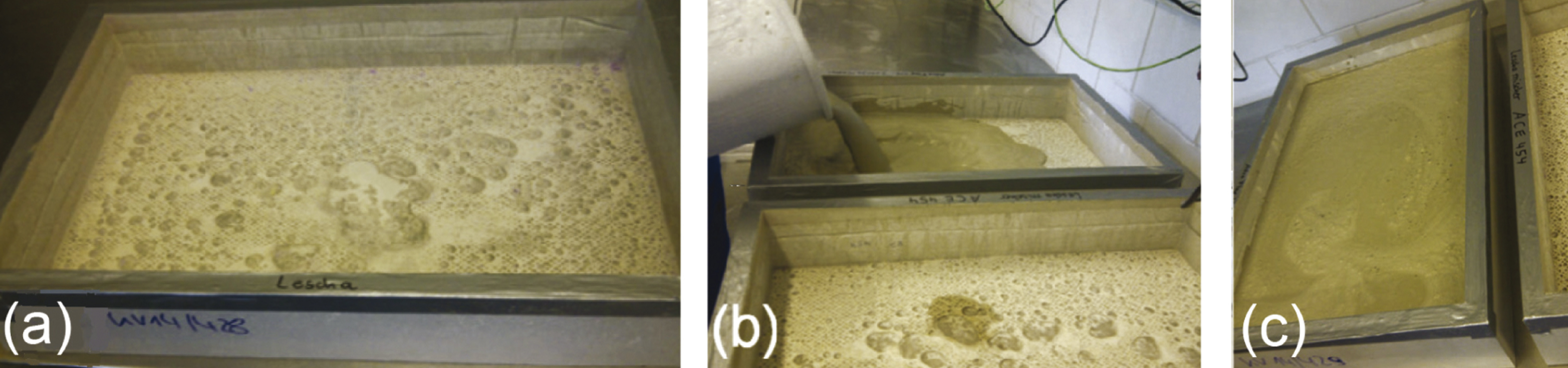
Fig.9
Manufacturing of UHPC-CLC small-scale samples. (a) Cast of CLC. (b), (c) Homogenous distribution of CLC in the UHPC box.
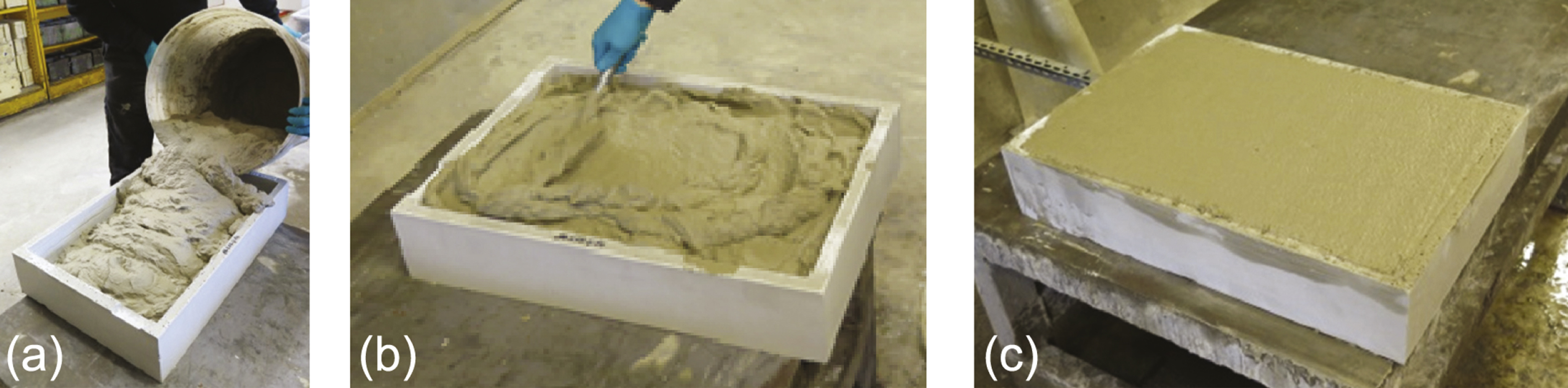
Table 1
Geometrical parameters of half panels
| Insulation | L × H | UHPC ext. layer | Insulation | Total | Total | Weight |
| (m2) | thickness (mm) | thickness (mm) | thickness (mm) | weight (kg) | (kg/m2) | |
| AAC | 5 × 3 | 30 | 350 | 380 | 1880 | 125 |
| CLC | 5 × 3 | 30 | 350 | 380 | 2340 | 156 |
Table 2
Composition of UHPC mixtures and obtained density
| Material | Nanodur® Compound 5941 | Sand | Superplasticiser | Water | Dry density |
| (kg/m3) | 1050 | 1150 | 17.9 | 178.5 | 2440 |
Table 3
AAC. Range of mix proportions tested and obtained densities
| Material | Cement | Sand | Quick lime | Anhydrite/Gypsum | Mineral aggregate | Aluminium* | Dry density |
| (kg/m3) | 250–500 | 250–400 | 50–250 | 30–70 | 100–200 | 5–8 | 85–115 |
*used as porosing agent/blowing agent.
Table 4
CLC. Range of mix proportions tested and obtained densities
| Material | Cement | Sand | SP | w/c | VF (l) | Density | ||
| Target | Wet | Dry | ||||||
| (kg/m3) | 72–303 | 76–258 | 0.4–1.8 | 0.25–0.5 | 737–952 | 155–637 | 165–958 | 175–734 |
SP, superplasticizer; VF, volume of foam.
Table 5
Strength properties and results from drying shrinkage tests for different material mixtures
| Material | Shrinkage (%) | Water | Fibres | Density | Flexural | Compressive |
| mixture | addition (%) | (kg/m3) | strength (N/mm2) | strength (N/mm2) | ||
| DIN 18947 | min. 2a/3b/4c | According to | – | min 0.9 | min 0.7 | min 1.5 |
| manufacturer | max 2.2 | |||||
| ND_GI<0.5/EPB | 2.3a | 25 | straw | 1.60 | 0.3 | 1 |
| ND_GI 0.5/M16 | 5.6 | 23 | – | 1.45 | n/a | n/a |
| ND_PI /EPB | 1.7b | 27 | straw | 1.75 | 0.9 | 2.5 |
| ND_PI /M16 | 6.6 | n/a | – | |||
| ND_PI/EPRF | 2.9b | 24 | straw | 1.79 | 0.9 | 2.4 |
| ND_PI/EPRFfine | 1.9b | 26 | straw | 1.72 | 0.6 | 1.6 |
| ND_PI/EPFF | 3.3c | 26 | cellulose | 1.79 | 1.3 | 3.7 |
| ND_PI/EPFFfine | 3.6c | 28 | cellulose | 1.75 | 1.1 | 3.1 |
| CMS_GI/EPRF | 0.8c | 23 | straw | 1.47 | 0.1 | 1.4 |
| CMS_GI/M16 | 2.4b | 25 | hemp | 1.37 | 0.3 | 1.2 |
| CMS_PI/EPRF | 1.9b | 25 | straw | 1.71 | 0.4 | 1.2 |
aupper limit for mineral earth coat.
bupper limit for earth coat, stabilised with fibres.
cupper limit for thin earth coat, stabilised with fibres. Inacceptable results marked in grey. n/a = not available.
Table 6
Physical and thermal properties of the materials used
| Component | Function | Dry density (kg/m3) | Thermal conductivity (mW/(m·K)) |
| UHPC | Structural | 2500 | 1500 |
| AAC | Insulation | 85–95 | 42* |
| CLC | Insulation | 180 | 45 |
*Here, the design-value λD of 42 mW/(m·K) corresponds to a λ10,dry-value ≤39.2 mW/(m·K) 0.


