
Total microfluidic platform strategy for liquid biopsy
Abstract
A liquid biopsy is a simple and non-invasive biopsy that examines a range of information about a tumor through a simple blood sample. Due to its non-invasive nature, liquid biopsy has many outstanding clinical benefits, including repetitive sampling and examination, representation of whole mutations, observation of minimal residual disease etc. However, liquid biopsy requires various processes such as sample preparation, amplification, and target detection. These processes can be integrated onto microfluidic platforms, which may provide a sample-to-answer system. The present review provides a brief overview of liquid biopsies, a detailed review of the technologies in each process, and prospective concluding remarks. Through this review, one can have a basic but cross-disciplinary understanding of liquid biopsy, as well as knowledge of new starting points for future research in each related area.
1Introduction
A liquid biopsy, which is an alternative to surgical tissue biopsy, is a simple and non-invasive biopsy that examines a range of information about a tumor through a simple blood sample. Since the liquid biopsy yields outstanding advantages including non-invasive sampling, repetitive sampling and examinations, representations of whole mutation etc., it is rapidly propagated to microfluidic researchers as well as clinicians. In particular, the non-invasive nature of liquid biopsies, which requires only 5 ml of blood, is much easier and more tolerable than surgical biopsies. Tolerability and convenience of liquid biopsy can provide various benefits for patients and doctors. The biggest benefit lies in the potential of liquid biopsy to detect disease progression or treatment resistance before it triggers clinical symptoms or appears on imaging scans.
There have been debates on whether liquid biopsy, which works by detecting circulating tumor DNAs (ctDNAs), is as effective as traditional tissue biopsy. However, these debates are beginning to fade with recent comparison studies. For instance, Wyatt et al found a high correlation between driver mutations in plasma circulating tumor DNA (ctDNA) and metastatic tissue biopsies in castration-resistant prostate cancer [1]. This study demonstrates that, in the majority of patients, a ctDNA assay is sufficient to identify all driver DNA alterations present in matched metastatic tissue. This supports the development of DNA biomarkers to guide cancer patient management based on ctDNA alone.
Liquid biopsy, which is in an early stage of technical development, calls for innovative technology and the convergence of various disciplines. A promising technology is microfluidics, which has been brilliantly developed in the last few decades. A digital droplet polymerase chain reaction (ddPCR) yields the highest sensitivity to detect ctDNA in blood. However, the ddPCR cannot satisfy clinical needs, which require high-multiplexing of more than several hundreds of potential ctDNAs. Thus, the present protocol for liquid biopsy is based on NGS with additional ddPCR. In addition to detection technology, liquid biopsy requires plasma extraction from whole blood, DNA extraction from plasma, etc. As we review each theme below, we will recognize that there is sufficient room for microfluidic technology to contribute in the whole process of liquid biopsy.
Therefore, understanding the unmet needs of clinics, it is imperative to review each technology and methods. The first part of the review is about sample preparation for plasma extraction. The second is on DNA extraction from extracted plasma. The last part is about detection methods and techniques for liquid biopsy. After reviewing the updated technologies, comparisons will be given in specific measures such as throughput, purity, limit of detections, etc.
2Blood cell separation: Plasma extraction
Blood plasma is the basic fluid of our body as well as an easily accessible source of circulating biomarkers for molecular diagnosis. Plasma is preferred over serum when taking blood samples [2], although serum contains circulating DNA as well [3], because the preparation of serum could cause unwanted release of nucleic acids due to cell lysis of non-cancerous cells [4]. Extraction of pure plasma is one of the most important steps for precise analysis of target biomarkers, especially in analyses using circulating nucleic acids that require compatibility with a gene amplification process such as the polymerase chain reaction (PCR) or isothermal amplification techniques [4]. It has been reported that impurities from blood cells, such as haemoglobin [5], heme [6], and lactoferrin [5], could inhibit PCR by regulating the activity of the polymerase.
The most commonly used method to remove blood cells is centrifugation. It is currently the gold standard technique for plasma extraction with a high yield, high purity, and stable reproducibility. However, this method is hard to integrate with biosensors because it occupies considerable space, requires batch-processing, and is performed manually as a multi-step process, which can lead to human error. Furthermore, the transportation of a blood sample needs to be minimized because prompt centrifugation could reduce blood cell lysis and release of germline DNA, which otherwise would dilute the circulating target nucleic acids [2, 7–10].
2.1General microfluidic approaches
In general, passive separation tends to be preferred over active separation because passive methods have less complex device design, can perform at relatively high flow rate, and are relatively easy to integrate with biosensors [11]. The passive methods are mainly utilizing biophysical effects of the blood cells in microscale channel flow and hydrodynamic forces to induce natural behaviors of red blood cells (RBCs) in the microfluidic channel, such as the cell-depletion layer [12–17]. Fahraeus effect [12, 18–21], the Zweifach-Fung bifurcation law [22, 23], and deterministic lateral displacement (DLD) [24, 25], all three described next.
When blood flows through a channel, the RBCs tend to move towards the center so that blood flow is divided into a concentrated region in the central part and a depletion region near the wall [13]. It is called the cell-depletion layer. The Fahraeus effect refers to the decrease in hematocrit (concentration of blood cells) with decreasing capillary diameter. This effect is caused by the presence of a cell-depletion layer, which takes a larger fraction of a micro-sized than a large tube diameter. The effect of the cell-depletion layer is significant in capillaries with diameters less than 300–400μm [19]. The Zweifach–Fung bifurcation effect means that the RBCs tend to prefer the large branch with high flow rate and is frequently observed at bifurcations of microchannels. When there is an asymmetric bifurcation with different branch diameter, a lower density of RBCs and even pure plasma can be achieved in the small branch [26]. The DLD method determines the flow paths of particles, according to their sizes, through multiple microposts with controllable spacing. DLD is frequently used for cell separation as well as plasma extraction from whole blood [24, 25].
The Zweifach-Fung effect has been adopted in microfluidic devices for plasma extraction [27]. Additional geometric features, such as constriction and expansion of the channel and the appropriate repetition or curvature of the channel, can further improve plasma extraction [28–32]. The Agarwal group designed simple T [29] and Tau-microchannels [28, 30] and tested whole blood samples (Hct 7% –45%) at 0.3–0.5 ml/min [28]. A separation efficiency of around 80% from whole blood (Hct 45%) and near 100% from a diluted sample (Hct < 15%) was reported, while the yield was 3% using whole blood. In recent research, they not only developed a separation efficiency close to 100% at a wide range of Hct (7–62%) with a yield range from 1 to 6% but also conducted a quality check by measuring the glucose and human chorionic gonadotropin (hCG) [31]. Another case of improvement for plasma separation devices was provided by Marchalot et al. [33]. They connected two plasma separation units [34] in a multi-step set-up, obtaining a microfluidic system at an 18% –25% yield for 1:20 diluted blood. The quality of the plasma was investigated by contamination of other blood cells. Kerhoas et al. investigated circulating nucleic acids in a plasma extracted from a microfluidic device [32]. Although only the sample preparation for blood plasma extraction was done on a chip, this research involves the whole process (e.g., plasma separation, gene amplification, and detection), which a sample-to-answer system should cover.
Inertial microfluidics has been intensively studied and utilized as one of the main techniques for plasma separation [35]. Various applications, such as a constriction–expansion array [36, 37], dean flow [38, 39], and serpentine channels [40], have been reported. Song et al. developed a device to extract plasma that can replace external pumping equipment with simple pipetting by the user [36]. The blood cells were autonomously focused along the walls in a series of expansions and the wall inclined to the vertical direction (85 degree) and then removed through outlets at the end of both sides. In recent work, a pattern of slant ridges was utilized to obtain high purity and high throughput with an additional air chamber to maintain equal pressure during the device operation [41, 42]. The inertial dean flow in the spiral channel can be a proper approach to extract plasma under dilute conditions, even though it could be suitable for a rare cell isolation technique, such as CTC (circulating tumor cells) [43–45]. Generally, however, samples applicable to extract plasma in inertial dean microfluidics tend to be restricted to highly diluted blood, i.e., less than 5%. A multiplexing device with tilted 16-spiral channels show a high throughput of 24 ml/min and 100% efficiency from 1:20 diluted blood [38]. In this study, the authors claimed a high yield close to 50%. Similarly, another recent study reported an efficiency of around 99% and yield of 95% with an optimized flow rate of 1.25 ml/min [39]. The yield was calculated by the difference in the fluorescent intensity from fluorescently labeled bovine serum albumin after passing through the Polydimethylsiloxane (PDMS) device, because the protein could be absorbed into the PDMS wall, which could cause loss of the target analyte. Even though the inertial dean flow shows a high plasma separation, the application of spiral dean flow in plasma separation requires further validation of clinical trials by quantifying the recovery rate for the circulating nucleic acids.
Fig. 1
(A) Image of plasma extraction using a bifurcating channel (adapted with permission, reference [27]). (B) Top: Image of a blood plasma separation device using multiple hydrodynamic effects and bottom: plasma separation in a curved and expanded microchannel (adapted with permission, reference [28]). (C) Smart pipette device with 8-parallel channels (top), operating image of the smart pipette for high throughput plasma separation (right bottom). Expended images show the migration of blood cells due to the slant array ridges (adapted with permission, reference [42]). (D) Top left and bottom: microscope image at the end of the spiral microchannel for plasma separation and top right: picture of the fluidic device (adapted with permission, reference [38]). (E) Picture of a device composed of multi-step units for plasma separation utilizing the optimized cell free layer effect according to the channel design (adapted with permission, reference [33]). (F) CD-based plasma separation device that can handle large volume of blood sample. Pictures 1 to 4 indicate sample loading, primary sedimentation, total plasma separation, and plasma transferring into another chamber, respectively (adapted with permission, reference [46]).
![(A) Image of plasma extraction using a bifurcating channel (adapted with permission, reference [27]). (B) Top: Image of a blood plasma separation device using multiple hydrodynamic effects and bottom: plasma separation in a curved and expanded microchannel (adapted with permission, reference [28]). (C) Smart pipette device with 8-parallel channels (top), operating image of the smart pipette for high throughput plasma separation (right bottom). Expended images show the migration of blood cells due to the slant array ridges (adapted with permission, reference [42]). (D) Top left and bottom: microscope image at the end of the spiral microchannel for plasma separation and top right: picture of the fluidic device (adapted with permission, reference [38]). (E) Picture of a device composed of multi-step units for plasma separation utilizing the optimized cell free layer effect according to the channel design (adapted with permission, reference [33]). (F) CD-based plasma separation device that can handle large volume of blood sample. Pictures 1 to 4 indicate sample loading, primary sedimentation, total plasma separation, and plasma transferring into another chamber, respectively (adapted with permission, reference [46]).](https://content.iospress.com:443/media/jcb/2020/6-2/jcb-6-2-jcb200027/jcb-6-jcb200027-g001.jpg)
2.2Centrifugal microfluidics
In the conventional method, the plasma can easily be separated by using a centrifuge because of the density difference between blood cells and plasma. Likewise, applying centrifugation in microfluidics is a simple and suitable approach to separate plasma from whole blood [47, 48]. The centrifugal force in microfluidics can provide an automatic, fast, and cost-effective system with many applications, such as a driving force to induce sample flow, flow control through valves, volume masuring, mixing, and flow switching [47]. Furthermore, the centrifugal microfluidics have been studied with high potential to achieve a sample-to-answer system that can be integrated into a single disc [49–51].
It is important to note here that the Lab-on-a-Disk (LOD) based technique has a higher yield of plasma extraction than other separation techniques. For example, the extraction yield of hydrodynamic plasma separation from whole blood is generally low (around 1–10%). It means that most of the blood sample is consumed without being delivered to the detection unit. Centrifugal microfluidics can reduce the required volume in sample preparation to a level similar to centrifugation. In addition, as the dilution issue is not critical for LOD-based sample preparation, blood samples with high hematocrit can be loaded in the device.
Plasma separation from whole blood in centrifugal microfluidics has been researched by several research groups [46, 52–57]. Zhang et al. separated plasma from a diluted blood sample (12% HCT) with high purity (around 90%) in a simple design of the channel [56]. Plasma separation by flow-induced membrane deflection with pneumatic valve control was conducted with a high purity (<20 residual cells/μL) as well as a high yield (around 80%) [53]. Haeberle et al. successfully extracted 2μl of metered pure plasma from 5μl of whole blood through sedimentation by a decanting mechanisms [53]. Zehnle et al. utilized capillary action to separate plasma from 40μl of whole blood in a siphon device by pneumatic action [55, 57]. Considering its high purity and yield, centrifugal microfluidics could be a proper approach for the sample preparation technique of a sample-to-answer system. However, the technical barriers to this method are quite high. A high level of technological maturity is required to design appropriate valves and channels and to control the flow sensitively. To treat a clinical sample, a high throughput separation technique at the milliliter scale is required because the concentration of cfDNA is very low in plasma. These are necessary technological advancements because blood samples are typically restricted to a relatively small volume in Lab-on-a-CD devices, as complete packing should be ensured to prevent leakage during high speed rotation in a confined device.
Table 1
Plasma extraction techniques in microfluidics. Throughput (mL/min) indicates loading flow rate of blood sample in microfluidic device and it was calculated as sample volume/duration in centrifugal microfluidics. Yield was derived as volume fraction of extracted blood plasma (%). Throughput and yield were normalized by haematocrit of the sample on the basis of 45%. Normalized throughput and normalized yield are shown in black and gray bar graphs, respectively. Purity indicates blood cell removal percentage in extracted plasma
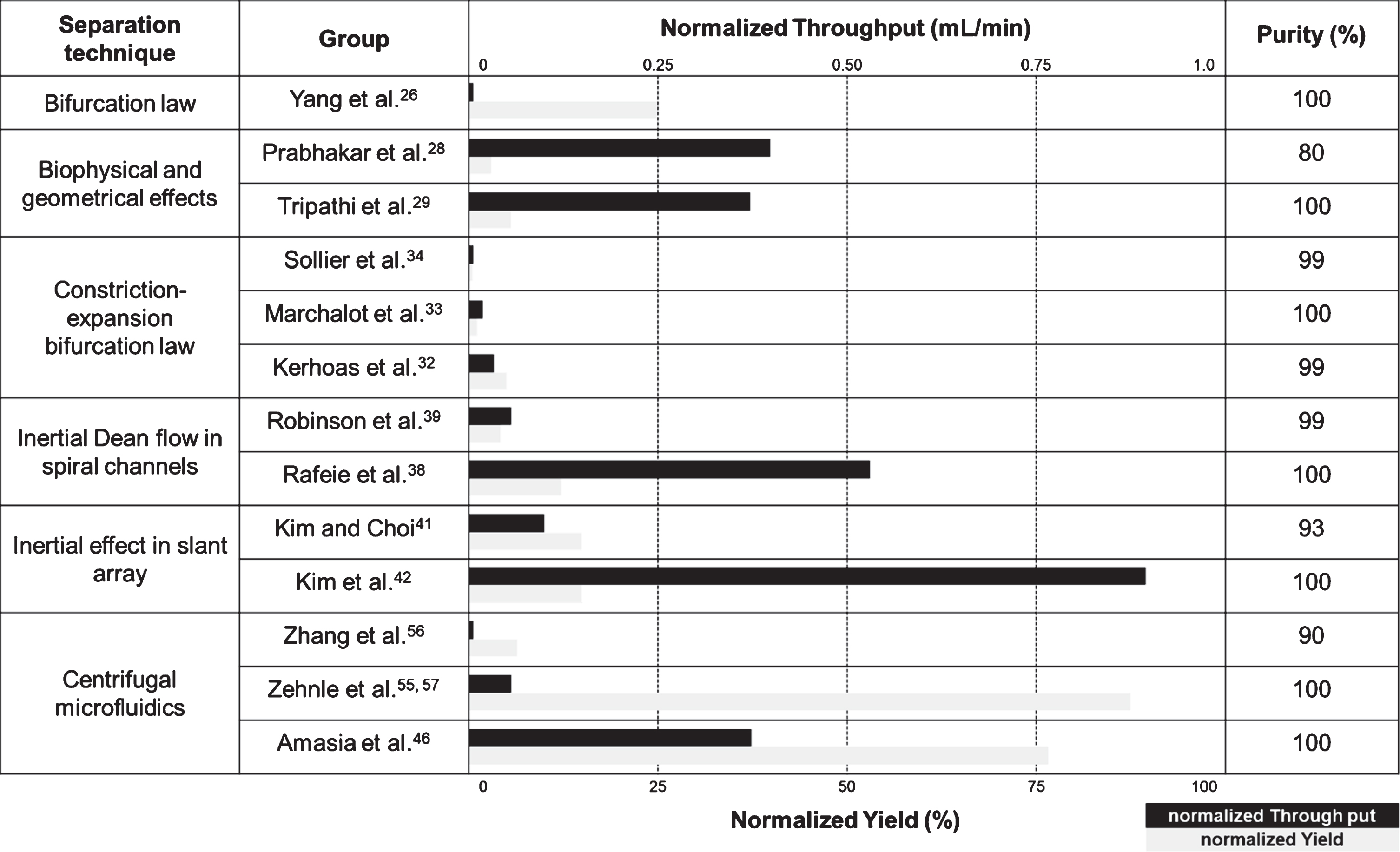 |
Large-volume plasma extraction was tried by Amazia et al [46]. They developed a device of centrifugal microfluidics to treat a large-volume undiluted blood sample. The device was designed as 1/4-inch-thick and with a CD radius. It successfully extracted plasma from 2 mL of whole blood with 99% purity and at a 77% yield. After finishing the cell sedimentation phase, the cell-free fluid was transferred to a collection chamber through a siphon valve that was controlled by the slow deceleration of the rotation. However, the quality of the bio-analyte in the plasma extracted through the microfluidic device was not verified.
2.3Perspective on blood cell separation in sample-to-answer system
There is no doubt about the high potential of microfluidic plasma separation for integrating sensor systems. However, further considerations have been raised for clinical application of plasma extraction in microfluidics. Being the first sample preparation process in a sample-to-answer system, the purity and yield of plasma extraction are highly crucial in ctDNA analysis. Although the strategies for plasma separation have been improved, the dilution and high throughput should be significantly improved to take advantage of microfluidics in real clinical situations. The crucial issue is the purity of plasma extraction in liquid biopsy. Any inclusion of blood cells or lysed components would aggravate the subsequent process of liquid biopsy such as PCR or a sensing process. Considering these issues, current microfluidic technology for liquid biopsy of cancers are not satisfactory compared to the conventional centrifugation method.
As we reviewed, the proposed microfluidic approaches are unsatisfactory for clinical application. However, these methods can be greatly improved by combining with either each other or adopting active separation technology. Although not mentioned in this section, active separation utilizing various fields (e.g., acoustic field, electrical field, magnetic field, and field flow fractionation), can be utilized for development of hybrid plasma separation with the passive methods [58, 59]. In fact, centrifugation-based microfluidics would be the most potent technique to extract pure plasma with high-throughput capacity, even though it requires further validation. Thus, one can start a liquid biopsy study with plasma rather than with whole blood because the plasma is extracted and stored in an easy and routinely manner in clinical environments until more advanced microfluidic technology is developed. After this section, the initial sample will be regarded as a plasma extracted by centrifugation.
3Nucleic acids extraction
Because circulating DNA is known as a major biomarker for precision medicine, liquid biopsy techniques are rapidly being developed such as genome-wide sequencing, next-generation sequencing (NGS), and droplet digital polymerase chain reaction (ddPCR). Most of these efforts have been focused on detection methods because of their extremely low concentrate of ctDNAs. Although many studies have reported considerable results with excellent sensitivity and specificity of sensing, all results assumed that the target DNAs were successfully extracted and purified for their sample. Without adequate nucleic acid extraction and purification technology, liquid biopsy using ctDNA cannot be made. Thus, efficient extraction of target analytes would determine the clinical applicability in molecular diagnostics. The loss of biomarkers could cause serious analytical errors in accurate molecular diagnosis and limit the reliability of the test. Furthermore, post-processing, such as gene amplifications or detection, could be inhibited according to the buffer condition of the final elute.
Fig. 2
(A) A polycarbonate microfluidic cassette capable of DNA and RNA extraction through a silica membrane to (RT-)PCR (adapted with permission, reference [60]). (B) Left: SEM image of micropillar structure in a flow channel and right: microscope image of glass-silicon bonded device (adapted with permission, reference [61]). (C) Image of microfluidic nucleic acid purification chip using phenol-chloroform method (adapted with permission, reference [62]). (D) Schematics of flow description (top) and picture of a microfluidic device for a continuous nucleic acid extraction kit using paramagnetic beads (adapted with permission, reference [63]). (E) SEM image of cross section of a bead packing channel for microfluidic DNA purification (adapted with permission, reference 64). (F) Image of electrokinetic microarray device with detailed description of materials and DEP positioning at a specific AC (alternating current) frequency (adapted with permission, reference [65]).
![(A) A polycarbonate microfluidic cassette capable of DNA and RNA extraction through a silica membrane to (RT-)PCR (adapted with permission, reference [60]). (B) Left: SEM image of micropillar structure in a flow channel and right: microscope image of glass-silicon bonded device (adapted with permission, reference [61]). (C) Image of microfluidic nucleic acid purification chip using phenol-chloroform method (adapted with permission, reference [62]). (D) Schematics of flow description (top) and picture of a microfluidic device for a continuous nucleic acid extraction kit using paramagnetic beads (adapted with permission, reference [63]). (E) SEM image of cross section of a bead packing channel for microfluidic DNA purification (adapted with permission, reference 64). (F) Image of electrokinetic microarray device with detailed description of materials and DEP positioning at a specific AC (alternating current) frequency (adapted with permission, reference [65]).](https://content.iospress.com:443/media/jcb/2020/6-2/jcb-6-2-jcb200027/jcb-6-jcb200027-g002.jpg)
The microfluidic technique is specialized for a small amount of target sample and has high potential to be integrated with the sensor. The miniaturization and automation of the nucleic acid purification on a microfluidic chip has been broadly investigated by many researchers. Even though cancer-derived cfDNA has its original characteristics, the fundamental principle of nucleic acid extraction can encompass liquid biopsy application regardless of the type of nucleic acids. Therefore, we provide a brief overview of the applicable techniques for cfDNA extraction in a microfluidic sample-to-answer system as well as in conventional ones.
3.1Conventional extraction of nucleic acid
The extraction of nucleic acids has been performed manually in the laboratory using either a spin column or magnetic beads. The common feature of these methods is to utilize DNA separation by silica adsorption, i.e., DNA molecules binding to silica surfaces in the presence of certain salts and under certain pH conditions [66, 67]. While a sample consisting of mixtures of various proteins, DNAs, phospholipids, etc., flows through the silica surface conduit, DNAs are adsorbed by the silica surface, while other components, such as plasma proteins, flow away. The DNA-silica binding (adsorption) involves a reduction of the negative charge of the silica surface, which leads to a decrease in the electrostatic repulsion between the negatively charged DNA and the negatively charged silica. However, because residual salts could inhibit the gene amplifying reaction of the enzymes [68], the salts as well as non-specific protein contaminants should be removed in a washing step using ethanol. The residual ethanol then needs to be removed because of the inhibition of DNA amplification [68, 69]. Then, the captured nucleic acids are eluted in a low salt buffer.
Thus, the spin column and magnetic beads use a silica membrane and silica-coated beads, respectively. However, these manual operations suffer from contamination and operator-dependence problems, because the procedures have a batch-type work flow, such as changing tubes and buffers or applying centrifugation under various conditions. To prevent cross contamination and improve the stability of the experiment, a few automated systems for extraction of nucleic acids are now commercially available. However, these systems have a high initial installation cost and a large volume consumption of buffers because the large device is using a liquid handler or because of the motion control of the magnet.
3.2Solid phase nucleic acid extraction in microfluidics
Solid phase extraction refers to a technique for selectively capturing nucleic acids on the surface of a solid material under specified buffer conditions. Typically, such techniques have been studied extensively utilizing membranes, micro-patterned devices, and beads.
3.2.1Microstructure-based technique: Membrane and micro-patterning
Membranes can be considered microstructural materials because they are composed of bundles of micro-sized capillaries. Silica membranes have been used widely in commercialized spin columns for solid phase nucleic acid extraction. Integration of silica membranes in microfluidics is one of the simple methods for DNA extraction in a fluidic device [60, 70, 71]. Similar to conventional DNA extraction, high concentrations of salts are frequently adopted in microfluidics. Typical salts are chaotropic salts such as guanidinium thiocyanate and sodium perchlorate [66, 67]. After binding the DNAs on the silica surface, the residual salts as well as unwanted protein contaminants should be removed in a washing step using ethanol. Furthermore, any residual ethanol should be removed because it inhibits DNA amplification [68, 69]. Then, the captured nucleic acids are eluted in a low salt buffer. Many studies introduced silica membrane-based microfluidic systems for nucleic acid extraction [60, 70, 71]. and some of them are fully automated, self-contained, and disposable. A few studies introduced sample-to-answer systems, fully integrated with gene amplification processes and target detection sensors [60, 72].
Likewise, aluminum oxide membranes can be utilized instead of silica membranes with strong binding of nucleic acids at high salt concentrations [73, 74]. The major advantage of aluminum oxide membranes is that they do not inhibit PCR because of elimination of ethanol in the washing process, as aqueous NaCl [75] or KCL [73] solutions can be utilized in the membrane. It should be noted that the nucleic acids stay immobilized on the alumina surface because of the tight bond, even in the presence of components of the PCR reaction. While it was reported that DNA can be eluted by adding bovine serum albumin and Taq polymerase to the PCR buffer [74], the tight binding property allows the post-PCR reaction to be applied continuously to the membrane. In recent research, chitosan-modified filter paper was embodied in a microfluidic device and DNA was successfully extracted under pH control; binding at pH 5 and elution at pH > 8 [76]. Although these systems successfully purified and detected target nucleic acids with elaborately designed channels and valves to control each phase of the extraction process, they were primarily developed to detect virus and bacteria from whole blood [70, 76] or saliva [60, 71].
Similarly, the microstructural patterning to apply maximized surface area have been investigated. Microstructure patterning increases the flow disturbance and improves mixing, which can provide more opportunities for DNA to contact the binding region [77]. The fluidic devices consisting of microstructures were generally fabricated ON silicon or glass substrates, which patterned the miropillars [61, 78–81] or parallel channels [82]. Generally, the microstructure using a silica surface has the following advantages; it is reusable, no post-fabrication is required, and high flow rates are possible [83]. Especially, the compatibility for loading a high sample volume in the device is critical for most of clinical applications. West et al. showed that the micro-patterned channel can adapt a high flow rate, ranging from 5 to 500μl/min, while the DNA elution at a high flow rate decreases with flow rate. The yield of DNA was 55% at 500μl/min compared to 5μl/min. The key factor to determine the DNA extraction efficiency is the shape of the microstructural patterning of the channel. Min et al. investigated the DNA extraction efficiency according to various micro-pattering dimensions (pillar diameter, gap size, chamber volume, surface area, and surface to volume ratio) and they indicated that the DNA binding capacity was proportional to the surface to volume ratio [84]. Pyramidal pillars showed better DNA extraction efficiency than frustoconical pillars due to increased flow disturbance [77]. The limitations of micro patterning are: high cost, time-consuming, and complex fabrication process. However, because the semiconductor manufacturing industry has widened its application in the biomedical fields, micro-patterning could be a potent technique of liquid biopsy in clinics.
3.2.2Bead-based technique
Another approach to apply a large surface area in nucleic acid purification is the bead-based method. Bead-based nucleic acid extraction has been utilized as one of the basic concepts of a commercial kit to substitute for centrifugation. Some studies found that bead-based cfDNA extraction improved the extraction yield and the quality of the circulating nucleic acid [85–88]. Jorgez et al. explained the improvement by arguing that beads can maximize the contact between the surface matrix and DNA, resulting in better absorption of DNA on the silica surface [86].
Bead packing in a microchannel is a direct adaption of a macroscale bead-based extraction [64, 89–91]. Tian et al. showed that fast DNA purification (<10 min) was effectively miniaturized using packed silica particles in a capillary [91]. The binding capacity of silica beads for DNA as well as RNA, which was packed in a channel, was investigated [89]. In addition, bead packing using chitosan-coated silica particles showed enhanced nucleic acid extraction efficiency in both DNA and RNA due to the high affinity of the nucleic acids bound to the chitosan surface [90].
Because the bead can be easily collected by incorporating paramagnetic materials, the bead-based technology has successfully replaced centrifugation processes and eliminated the need for a syringe pump to allow flow through a packing channel [92]. Nucleic acid extraction in a bead is still a restricted solid phase extraction at the binding surface. However, the beads can be suspended homogeneously several times using paramagnetic characteristics, so that nucleic acid binding could occur like in semi-liquid phase extraction. Furthermore, freely mixed beads can maximize the binding capacity of the bead surface and consequently reduce the use of the overall bead amount and total cost.
Table 2
Nucleic acids extraction techniques in microfluidics
| Category | Technique | Materials/methods | Advantage/disadvantage | Integration difficulty |
| Solid phase extraction | Membrane | Silica membrane [60], aluminium oxide membrane [74], chitosan membrane [76] | Well developed in commercial product, disposable, easily integrated into microfluidic devices | Low |
| Difficult to completely elute buffer inside the membrane, use of PCR inhibition buffer (silica membrane) | ||||
| Micro-patterning | Micro-patterning [77, 84, 80], integration with gene amplification [77] | Handling high flow rate, large surface area, reusable device | High | |
| Expensive and difficult to fabricate device, use of PCR inhibition buffer | ||||
| Bead packing | Silica bead packing [89, 91] | Inexpensive, disposable, ease fabrication in a tube | Low | |
| Low reproducibility of bead packing, high flow resistance, use of PCR inhibition buffer | ||||
| Paramagnetic bead | Conventional [93], unconventional [94], phase-transfer magnetophoresis [63] | Well developed in commercial product, freely resuspended and collected, large surface area | Moderate | |
| Relatively expensive, restriction in channel design | ||||
| Liquid phase extraction | Electrophoretic isolation | Gel electrophoresis [95], DEP [65] | No PCR inhibition buffer used, no flow driving parts required | High |
| Additional device to generate electrical power required, difficult to be integrated with sensor | ||||
| Isolation using organic solvents | Phenol-chloroform [62] | High extraction yield, widely used method in manual extraction | Moderate | |
| Use of toxic solvents, many handling steps |
The current use of paramagnetic beads can be generally classified into conventional and unconventional techniques [83]. The conventional techniques are based on stationary beads with a flowing buffer, whereas the unconventional techniques are based on a stationary buffer with moving beads. The manual operation of the DNA extraction using magnetic beads is conducted in the conventional manner, but commercialized automation machines (KingFisher instrument; Thermo Fisher Scientific, and RCS instrument; Promega) prefer the unconventional technique by moving the magnetic handler with a fixed buffer chamber. Both of the existing methods can be adapted into microfluidic systems for cfDNA extraction (conventional [92, 93] and unconventional [94, 96] techniques), but it should be noted that the paramagnetic bead-based device originally has fewer degrees of freedom in the geometrical design to apply enough magnetic field, such as the thickness of the wall [92], device material [92], and channel design to minimize loss of beads [83]. To control the motion of paramagnetic beads, an additional electric or mechanical part is required. For example, Lien et al. used a built-in microcoil array to generate a magnetic field by applying an electrical force [93] and Duarte et al. placed an external magnet to hold the paramagnetic bead and motorized rotating magnet under the fluidic device to mix beads and buffer due to bead agitation [92].
Solid phase DNA extraction including beads and membranes has a fundamental limitation in its inconsistent work flow. However, microfluidics can significantly reduce the work load and integrate the complex process into one continuous process. Karle et al. developed a phase-transfer magnetophoresis device that continuously extracts DNAs in fluidics devices [63, 97]. They designed microchannels of binding, washing, and elution buffers to flow around a magnet rotating at the center of the device. Beads that captured DNAs were continuously transferred from channel to channel from the binding buffer to the final elution buffer. Robust mixing was periodically employed in the rotating magnetic field, changing it from strong to weak magnetic field. Magnetic beads were aggregated and forming flagella-like chains in the strong magnetic field phase. Then, they were carried away by the flow in the weak magnetic field phase. The authors claimed that the continuous on-chip DNA extraction improved the extraction efficiency by on average 147% compared to batch-wise bead extraction test in a tube. This technology has the potential to be directly integrated with continuously flow- through micro-PCR and flow-type detector for sample-to-answer systems.
3.3Liquid phase nucleic acid extraction in microfluidics
Liquid phase extraction is a method to purify nucleic acid without intermediate substances such as solid material and target capturing probes. Solid phase extraction enhances the limitation of the immobilized surface through resuspension of the paramagnetic beads. However, its extraction efficiency depends on the ability of the solid material to capture nucleic acids. Liquid phase extraction in microfluidic application can be categorized in two methods utilizing either an electrical field or an organic solvent.
Gel electrophoresis, which is the basic approach of size-based nucleic acids separation based on the electrophoretic mobility of negatively charged nucleic acids, has been investigated in microfluidic chips [95, 98]. In microfluidic gel electrophoresis, the target nucleic acids, which migrated through the gel region, was easily purified into a TBE buffer filled chamber without additional gel isolation processes [98]. Another example of electrophoresis is microfluidic isotachophoresis (ITP), which consists of two buffers (a leading and trailing electrolyte) to which are applied high electric field gradients, enabling simultaneous concentration and separation of ionic analytes [99, 100]. Because the two buffers have higher and lower electrophoretic mobilities than the target nucleic acids, the DNAs can be focused in the interface of the heterogenous buffers. A direct application is to extract cancer-derived ctDNA from human blood using dielectrophoresis (DEP), which isolates nucleic acids using the characteristic movements of the analytes in an inhomogeneous electric field [65]. When applying an AC voltage, the circulating DNAs from chronic lymphocytic leukemia patients were concentrated at a positive DEP position, while other blood cells were located at a negative DEP position. After the blood cells had been washed with a TE solution, the remaining 25μL of the TE solution was eluted when the electrical field was turned off. The amount of ctDNA extracted in the electrokinetic microarray device was comparable with the commercial QIAgen spin column kit. Furthermore, the IGHV sequencing analysis of all 15 patients with chronic lymphocytic leukemia obtained by the microfluidic device and QIAgen kit exactly matched that of leukemic B-cell DNA.
Another example of liquid phase extraction is by using an organic solvent. The most important advantage of the nucleic acid extraction method is the high extraction efficiency. In general, phenol-cholochrome isolation has been known as a high throughput method [101]. Although the phenol-cholochrome method is time consuming, inconvenient, and relatively dangerous (it uses a toxic solvent), the solid phase extraction is preferred, despite the high yield of the liquid phase extraction. However, a high throughput extraction technology could be suited to detect extremely rare mutations in liquid biopsy, because the loss of one target gene can cause diagnostic errors. Zhang et al. successfully developed a microfluidic device for phenol-chloroform extraction [62]. They controlled the fluidic solvent and nucleic acids extraction process with a vacuum pump and pinched valve. According to the pH of the organic solvent mixture, RNA (pH = 8) or DNA (pH = 4.6) can be selectively purified in the device. In addition, the recovery yield of nucleic acid was up to 10 times higher than for a conventional column-based solid phase kit. For practical applications, the device should ensure safe handling of the organic solvent and the used solvent should be properly disposed [83].
3.4Perspective on nucleic acid extraction in sample-to-answer systems
Nucleic acids extraction in microfluidics has been successfully implemented through various techniques. Although microfluidic studies aiming directly at circulating nucleic acid analysis have not progressed much, most of the microfluidic techniques can be applied in the sample-to- answer systems of liquid biopsy. In addition, because cell lysis process is not required for cfDNA isolation, the device can be more simplified than genomic DNA extraction. Thus, microfluidic miniaturization can incorporate separate steps: DNA binding, washing, drying, and elution on a single chip using a small-volume sample with a high extraction efficiency of the circulating DNA. However, the nucleic acid isolation technique should be evaluated regarding whether it interferes with the gene amplification and target sensing mechanisms, whether it can relate to a minimal driving device in a fluidic system, and whether the DNAs especially short fragment of around 170 bp are sufficiently extracted to detect rare mutations. In this review, the targeted capture of nucleic acids with specific oligonucleotides was not included, considering universal sample preparation that would be broadly integrated with various sensor part, because sequence-based hybridization in the DNA preparation process could restrict diversity of the analytical application.
4Nucleic acids detection
The final goal of liquid biopsy is biomarker detection for diagnosis of diseases. As discussed earlier, typical biomarkers in liquid biopsy are CTCs, exosomes, proteins, and cfDNAs in the blood. Among these, cfDNA is the most spotlighted biomarker. It contains important information for diagnosis, prognosis, and monitoring of targeted therapies, because the cfDNAs contain critical genetic information of the mutants in cancer diagnosis [102]. Because detecting gene mutations is a very sophisticated analysis at the molecular level, the current method of analyzing the information of cfDNA in the clinical field is split in two. One is to analyze the whole genomic information using either whole exome sequencing (WES) or next-generation sequencing (NGS). The other is that the existence of a specific target gene can be examined with an highly sensitive detection device such as digital PCR (dPCR) [103]. The former can detect various gene mutations (ctDNA) from cfDNAs. However, because of its sequencing techniques, this method suffers from low sensitivity, high cost, and a long turnaround time. The latter is satisfied with its high sensitivity but is limited for multiplexing. Thus, the related communities have a high demand to develop an innovative molecular diagnostic method with high sensitivity and multiplexing capability. Additionally, a cost-effective and fast test is frequently requested for clinical use.
Fig. 3
The strategies of nucleic acids detection.
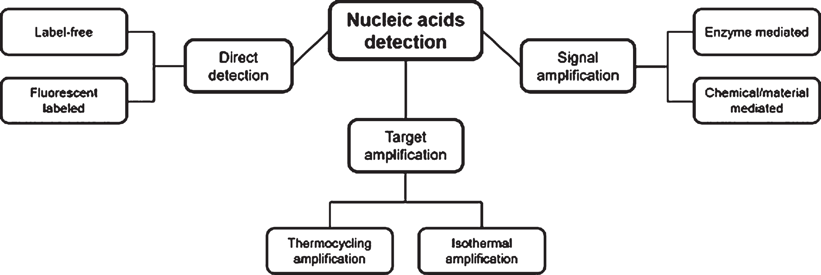
A key issue in DNA detection methods is “how do we detect an extremely low concentration of ctDNAs sensitively and selectively?”. Various methods have been developed to detect low concentrations of target DNAs and these methods can be classified in three categories as follows: 1) Direct detection methods for target DNAs using high sensitivity sensors, 2) Pre-amplification and detection of target DNAs and methods, and 3) Signal amplification methods for amplifying the detection signals of the sensor. Each method combines various mechanisms, enzymes, signal amplifiers, and sensors to detect the target DNA. In this section, we provide a brief overview of the techniques for target DNA detection that can be applied to sample-to-answer systems.
4.1Direct detection methods
Direct detection methods detect target DNA using highly sensitive sensors. The focus is on lowering the detection limit of the sensor. However, because the amount of cfDNA is very small, additional nucleic acid amplification steps are generally required prior to the detection step. Theoretically, if one copy of the target DNA is present, amplified DNA at the 2 pmol / 20μL (100 nM) level can be obtained by 40 cycles of PCR. The minimum sample volume used to analyze the amplified DNA may be greater than 20μL depending on the sensor used, so lower detection limits may be required considering sample dilution.
4.1.1Label-free detection
Label-free methods detect target DNA without using any additional signal generation material. Therefore, it can be regarded as the simplest method to detect the target DNA present in the sample solution.
Electrochemical sensor-based label-free methods have been developed for direct detection of target DNA [104–107]. Wang et al. [106] applied thin-layer MoS2 on the electrochemical sensor surface. MoS2 is a 2D layer material that is spotlighted for its excellent optical, mechanical, and electrical properties. The single-stranded probe is absorbed by MoS2 and immobilized on the surface of the DNA sensor. When the target DNA is hybridized with the probe DNA, the affinity is changed, and it is separated from the MoS2 surface and a detection signal is generated. In this study, a very low detection limit of 19 fM was detected. A chip-based study using an electrochemical sensor has also been reported. Das et al. [104] detected circulating nucleic acid in serum using an electrochemical clamp assay. Clamp DNAs, which bind only to the nucleic acids other than the target nucleic acid, were introduced to allow selective detection. In this method, a chip-based electrochemical sensor successfully detected mutations within 15 minutes with high sensitivity and specificity.
A label-free electrical characterization method for target DNA detection using a field-effect transistor has been reported. Star et al. [108] described DNA detection using a chip with carbon nanotube network field-effect transistors (NTNFETs). NTNFET is a random network of nanotubes, covering a relatively large surface area between two metal electrodes. Notably, this study discriminated SNP. Because SNPs are the most abundant variants of the human genome and are involved in a variety of diseases, the need for sensitive and selective detection is important. This study was able to successfully discriminate SNPs as well as detect target DNA with the help of NTNFET. A DNA detection chip based on an organic thin-film transistor (OTFT) was also developed [109]. In this study, PNA was used as a probe to detect low concentrations of DNA. PNAs have greater selectivity, affinity, and stability than DNA due to charge-neutrality, which reduces the electrostatic repulsion between the two hybridized strands. With the help of high sensitivity PNA and OTFT, DNA concentrations of 100 nM could be detected.
Plasmonic-based label-free detection studies have also been reported [110–116]. Plasmonic sensors are very sensitive to changes in the evanescent field that occur when light enters a nano-sized metal. The detection range of the evanescent field is very short, below a few hundred nanometers, making it well suited for small molecule analysis. The method of analyzing the plasmonic phenomena occurring on the surface of nano-sized metal particles is called nanoplasmonics. The nanoplasmonic biosensor is applied to colorimetric analysis because the wavelength of the peak absorbance changes depending on the refractive index of the material bound to the surface. Su et al. introduced a PNA probe to control the aggregation and dispersion of gold nanoparticles (AuNP) [111]. In the well dispersed state of AuNPs, the plasmonic phenomenon absorbs light of a specific wavelength band, resulting in a vivid plasmonic color. On the contrary, when the AuNPs are aggregated, the plasmonic phenomenon is changed, modifying the color band because the wavelength band of the absorbed light is changed. The target DNA is identified by this color change. In this study, the target DNA was detected using a highly selective PNA probe, and the surprising result of detecting single-base mismatches was also introduced. With the help of the high sensitivity of nanoplasmonic biosensors, analyses yielding extremely low concentrations of DNA have been introduced [117]. Nanoplasmonic phenomena are sensitive to changes in the refractive index within a few tens of nanometers at the surface of a nanoparticle, so a very small amount of target DNA can be detected. Truong et al. proposed a low detection limit concentration of 111 aM as a result of detection using gold nanorods (AuNRs) [115]. In addition, Soares et al. showed that a PCR-amplified target originated from clinical samples could be applied to the clinical field by detection using nanoparticles [113]. This is a surface plasmon resonance (SPR) sensor that uses a nanometer-thick metal film instead of nano-sized metal particles. The SPR sensor has a longer range of evanescent fields than the nanoplasmonic sensor described above. Therefore, they are less sensitive than nanoplasmonic sensors because they cannot focus on small areas. Carrascosa et al. conducted an early detection of breast cancer using the SPR biosensor [112]. The detection limit condition was optimized to discriminate successfully between deletion mutant DNA and wild-type DNA of breast cancer, but the detection limit concentration was 50 nM. However, the SPR biosensors are still highly sensitive sensors compared to other sensors and require further study because they are powerful multiplexed detection platforms [114, 118].
4.1.2Fluorescence labeled detection
While the label-free methods use a complex sensor system to sensitively detect target DNA, fluorescence labeling has the advantage of detecting target DNA using a simple fluorescent reader.
A variety of fluorescence-based target DNA detection studies has been introduced [95, 119–123]. We will describe SNP detection using protein chip among fluorescence-based detection technologies [121]. In this study, MutS protein was introduced to discriminate SNPs. The MutS protein, an important component of the DNA mismatch repair system, can specifically recognize and bind all possible single base mismatches as well as 1–4 base insertion or deletion loops. The mismatch binding activity of MutS was used to detect various types of DNA mutations. They utilized fluorescence-labeled DNA, which was synthesized as a wild-type sequence with no SNP. When the fluorescence-labeled DNA was injected, a heteroduplex was formed in which one base pair of DNA was not hybridized. The chip-immobilized MutS can then selectively bind single nucleotide mismatches of double-stranded DNA by introducing a sample mixture into the sensor. This study successfully discriminated various SNPs and presented detection limits of 90 pM.
A fluorescence paper based microchip study to detect two target DNAs simultaneously has been reported [120]. An origami paper chip called oPAD consisting of 3 layers coated with a fluorescent probe and quencher designed in each layer. Four analysis regions were provided on one chip, and the presence of two DNAs was multiplexed by an AND / OR logic gate method using a combination of a fluorescence probe and quencher in each region.
4.2Target amplification methods
Target amplification methods amplify DNA so that a small amount of target DNA can be detected by the sensor with the signal generated from the amplified DNA. Because this approach involves the process of producing large amounts of amplified DNA products, a small amount of target DNA can be detected without investing excessive efforts to lower the detection limit of the sensor itself. Therefore, the target amplification methods are based on integrating the DNA amplification systems into the microfluidic devices or observing signals from amplified DNA products.
4.2.1Thermocycling amplification-based detection
PCR is a thermal cycling technique that amplifies the target DNA sequence with millions of copies. The sample DNAs experience around 40 repeated temperature cycles, including denaturation, annealing, and extension steps. Theoretically, a single target DNA is amplified to two DNAs through each cycle.
Among the target amplification methods, the most suitable detection method for ctDNA detection is the digital DNA amplification method introduced in 1999 [124]. The biggest obstacle to the detection of ctDNA is that the amount of wild-type DNA is relatively high compared to the mutant DNA. Therefore, it is difficult to detect mutant DNA due to the presence of excess wild type coexisting in the PCR tube. However, digital PCR divides the PCR reaction into millions of small volumes to ensure that only one cfDNA is contained within the confinement. Each partition generates a fluorescent signal through PCR only if a target DNA exists in the partition. Thus, the number of mutant DNAs can be accurately determined by enumerating the fluorescence of each partition. The digital PCR technology is further developed as fully-commercialized products, such as BEAMing [125–127] and ddPCR [128]. Both products are based on water-oil emulsion droplet technology, even though the droplet generation method differs between them. In ddPCR, for instance, the PCR reagents are divided into droplets by a microfluidic technique, PCR thermal cycling is performed, and fluorescence information is analyzed using flow cytometry. The techniques for each step in ddPCR and its applications in target detection have been developed in various microfluidic chip based studies, e.g., droplet generation for ddPCR applications [129, 130], microfluidic ddPCR [131, 132], and digital droplet loop-mediated isothermal amplification (LAMP) [133].
A DNA detection technique based on the target amplification method was implemented as a lab-on-a-chip. PCR-based gene amplification and real-time detection techniques were developed using recirculating PCR technology and localized surface plasmon resonance (LSPR) sensors [134]. The unidirectional flow is implemented as a microchip imbedded piezoelectric pump, and the sample recirculation system was implemented in a closed-loop microchannel. Three heaters are attached to the thermal cycling zone of the closed-loop microchannel and the target DNA present in the PCR reagent is recycled and amplified. Part of the closed-loop microchannel is equipped with an LSPR sensor, which monitors the hybridization of the PCR product in real time. The sensor, which is divided into two probe regions, detects the amplification results of two kinds of DNA in real time. The LSPR-based recirculation PCR system successfully detected the target DNA at 5 fg / mL within 15 min. This technology can be applied as a sample-to-answer system when integrated with the sample preparation process.
A study of a sample-to-answer system already implemented on a lab-on-a-chip has been reported [135]. When diluted whole blood is injected into the microfluidic chip, a cell lysis process is performed. The cell debris and PCR inhibitor are then removed by cross-flow filtration. Finally, the prepared sample is mixed with the PCR reagent and injected into the PCR chamber. When the prepared sample is injected, it is divided into two, mixed with PCR reagents, including different primers and probe sets, and injected into the PCR chambers separated from each other by an oil plug, thereby implementing multiple detection. The entire process could be completed within one hour. It should be noted that this study proposes an example of the ultimate goal of the sample-to-answer system.
4.2.2Isothermal amplification-based detection
An isothermal amplification method was also developed to amplify DNA at a constant temperature without the 3-step thermal cycling of the PCR. Because PCR-based DNA amplification methods involve different temperature setting for denaturation, primer annealing, and polymerase extension, there are difficulties to place a thermal cycling block or three independent heating blocks to build an integrated system. On the contrary, as isothermal amplification works at constant temperature and even at room temperature, an advantage is that it is easily applied in a simple device set up.
Isothermal amplification has been developed using various combinations of enzymes and nucleic acid probes. Furthermore, many studies utilizing isothermal target amplification have been implemented in chip-based applications, e.g., rolling circle amplification (RCA), [136–138] recombinase polymerase amplification (RPA) [139], LAMP [140, 141], helicase-dependent amplification (HDA) [142–144], and nucleic acid sequence-based amplification (NASBA) [145–147].
A microfluidic chip technology based RCA has been introduced for target DNA detection [136]. When a DNA amplification reaction occurs by the target DNA, a specially designed template is used to increase the viscosity of the amplified RCA product to generate DNA hydrogel. A micro channel filled with micro beads was used to widen the surface area where the reaction takes place and to reduce the area blocked by the DNA hydrogel. To check the channel blockage, the inlet was filled by a colored dye, and negative pressure was applied using a disposable syringe to examine the presence of target DNA by the naked eye through the dye flow. The detection limit of this detection technique is 0.1 pM, and the detection time is at least 15 minutes. It also enables multiple detection through 5 independent micro channels. The technology is aimed at virus detection but can also be used for general gene detection.
Chip-based DNA detection technology using isothermal RPA has also been introduced [139]. RPA amplifies DNA through the action of recombinase, single-stranded DNA binding protein (SSB), and polymerase. Recombinase binds the primer to anneal dsDNA and SSB binds so that unbound ssDNA does not become dsDNA again. The target DNA is replicated by primer extension with polymerase binding. In this study, the sticky end was designed to be present in the RPA product using a special primer. One side of the sticky end binds to the sensor surface and the other side binds to the reporter to generate a detection signal. In this study, detection limits using fluorescence signals and paper-based chips are 6 fM and 10 fM, respectively.
4.3Signal amplification methods
The signal amplification method is an approach to increase the detection signal of sensors when the target DNA is present. For instance, target DNA would act as a catalyst to amplify the detection signal. The advantage of the method is to reduce the risk of error signal generation during DNA amplification. In fact, when the DNAs are amplified, an error DNA could be produced due to incorrect binding between DNAs. If such an error DNA is generated early in the amplification process, the error DNA products will continue to be amplified and lead to false detection results. However, in signal amplification methods, only the detection signal is amplified without amplifying the target DNA, reducing the risk for false signals.
4.3.1Chemical/material mediated signal amplification
Chemical/material mediated signal amplification methods have been introduced to analyze various bio-analytes, such as cells, proteins, antigens, and nucleic acids. In particular, the application of this method of signal amplification is essential for ctDNA detection. Because the size of ctDNA is 100 nm or less and the molecular weight is significantly small, the detection signal generated from ctDNA itself could be insufficient. Therefore, a variety of signal amplification methods have been developed through nanomaterials and chemicals that have characteristics suitable for sensor platforms.
The most popular sensor for chemical/material mediated signal amplification is an electrochemical sensor, which analyzes electrochemical interactions such as oxidation-reduction reactions. Because large detection signals cannot be obtained with only DNA bound to the sensor surface, various electrochemical signal amplification techniques have been introduced. The simplest signal amplification method is that one probe linker captures multiple target DNAs [148, 149]. A supersandwich assay was introduced, a signal probe DNA capable of binding to the target DNA captured on the probe linker immobilized on the sensor chip surface [149]. Because the signal probe DNA has a sticky end that can bind to the target DNA again, the signal probe DNA and the target DNA alternately and continuously combine on the target DNA bound to one probe linker to amplify the signal. The detection limit achieved in this study is 100 pM. However, because the principle of signal amplification occurs when the target DNA is continuously captured in the sensor, there is a limitation that the detection signal cannot be amplified when the amount of target DNA is extremely small.
A study to amplify the electrochemical signals was reported by Yao et al. [150]. Two materials were used for signal amplification of electrochemiluminescent (ECL) sensors. First, nano-gold was immobilized on the surface of the sensor chip to increase the surface area of the sensor, allowing more probe DNA to bind to the sensor surface. Secondly, the detection signal was amplified using ferrocene-labeled target DNA. The probe DNA used in this study exists as a stem-loop structure. One end of the stem-loops is fixed to the sensor surface and the other is modulated by ruthenium. Ruthenium generates an oxidation/reduction reaction on the surface of the ECL sensor. When the target DNA binds to the stem-loop probe, the loop structure changes to a linear structure, and the ruthenium moves away from the sensor surface and the signal decreases. Thus, a decrease in the signal means that target DNA was detected. When the target DNA binds to the probe, ferrocene is present near the ruthenium of the stem-loop, and the ferrocene quenches the signal of ruthenium. Therefore, it is possible to amplify the signal reduction effect due to binding of the target DNA. With the introduction of signal amplification technology, this study succeeded in detecting 0.1 pM. Although the signal amplification effect by ferrocene labeling is excellent, a limitation is that it takes overnight to label ferrocene in the target DNA.
A paper analytical device (PAD)-based microchip technology using a stem-loop structure has been reported [151]. In this study, methylene blue was labeled as a stem-loop probe instead of ruthenium as described above, but the basic principles of signal generation are similar. The advantages is that you can analyze target DNA with a very simple operation by using a very small (2.3 cm wide and 4.0 cm long) PAD sensor.
DNA detection using a microarray is the most appropriate method for diagnosing cancer that monitors several mutations simultaneously. Spotted image results can be obtained using a single signal enhancer after introducing the sample on the sensor surface spotted with different kinds of probes. Signal amplification is essential for sensitive DNA microarray analysis. Taton et al. used an AuNP-labeled probe instead of a fluorescence-labeled probe, which is commonly used in commercial applications [152]. AuNP probes can be captured in a sandwich form on the array when the probe is immobilized on the array surface and the target DNA binds. To amplify the signal, silver ions are reduced by hydroquinone to silver metal at the surfaces of the AuNPs. This amplification allows us to provide a clearer microarray image, thus achieving a detection limit of 50 fM. In addition, this study discriminated single-base mismatched oligonucleotides by applying optimal detection temperatures.
Another silver enhancement-based technique has been reported to further increase the detection signal. In the technique described above, one target DNA could capture only one AuNP labeled probe. In this technique, the target DNA combined with the bar-code DNA carrier AuNP is collected with a magnetic microparticle so that one target DNA can generate a large number of bar-code DNAs [153]. The amplified bar-code DNA binds to the microarray and the AuNP probe, and a larger number of AuNP probes can be immobilized on the array surface. The signal amplification process based on silver enhancement technology was then used to achieve a detection limit of 500 aM. On-chip based microarrays have also been reported [154]. Nanophotonic structures, such as photonic crystals, can provide advantages in sensitive detection by amplifying optical signals. In this study, a photonic crystal array was fabricated using probe-linker immobilized 40 nm polystyrene particles. A photonic crystal amplified the fluorescence probe signal and succeeded in detecting SNP with a detection limit of 50 aM.
An AuNP catalytic growth technique for DNA detection signal amplification using an SPR sensor suitable for nano-size DNA analysis has been reported [155]. Catalytic growth of AuNP was employed as a detection signal amplification method for various sensors. However, the SPR sensor is difficult to apply because the surface of the sensor chip is also a thin gold film. In this study, a SiO2 layer was coated on the sensor chip surface so that catalytic growth did not occur on the sensor chip surface. A probe immobilized on the surface of the sensor and a probe immobilized on AuNP were bridged and amplified by catalytic growth. As a result, a detection limit of 4.8 pM was achieved. A DNA detection method using SPR imaging (SPRi) has been reported for multiple detection, which is an advantage of the SPR sensor. In this study, the detection signal was amplified using exonuclease III [118]. When the 5’ end of the probe linker is immobilized on the surface of the sensor chip and the target DNA binds to the probe linker, the exposed 3’ end of the probe linker is digested by exonuclease III to the end of the dsDNA. Target DNA is released and bound to another probe linker and the same process is repeated. Three deferent probe linkers were spotted on the SPRi sensor chip and it was confirmed that multiple DNA sequences were detected simultaneously on one chip with a detection limit of 10 pM.
4.3.2Fluorescence labeled detection
The key to enzyme-mediated signal amplification is to introduce enzymes and designing signal probes to allow a single target DNA to act as a catalyst. While the chemical/material mediated signal amplification methods mentioned above amplify only the signal generated from a single target DNA, the single DNA reacts with multiple signal probes with the help of enzymes to generate detection signals in enzyme mediated signal amplification methods. This method is called “target recycling” because one DNA is repeatedly involved in the reaction. The major advantage of target recycling is that it can greatly improve sensitivity because it can generate multiple detection signals even when low concentration target DNA is present. In addition, it can be applied to develop various detection assays using various signal probes suitable for each sensor systems.
Enzyme mediated signal amplification methods for electrochemical sensors have been reported. Wan et al. amplified the detection signal by introducing terminal deoxynucleotidyl transferase (TdT), which adds nucleotides to the 3’ end of the target DNA immobilized on the surface of the sensor [156]. The 3’ end of the probe DNA is immobilized on the sensor surface; then, there is no externally exposed 3’ end until the target DNA is present. When the target DNA binds to the probe DNA, TdT recognizes the 3’ of the target DNA and adds nucleotides. Among the nucleotides, biotinylated dATP is included, so biotin is present in the extended single-stranded DNA (ssDNA). Avidin-modified horseradish peroxidase (Av-HRP) binds to biotin and Av-HRP generates an electrochemical signal. TdT amplifies the signal with a mechanism that allows multiple Av-TdT to bind to each 3’ end of the target DNA. Through this mechanism, sensitive target DNA detection was achieved with a detection limit of 1 pM.
Another signal amplification method using exonuclease III has been reported by Xuan et al. [157]. An electrochemical molecular beacon (eMB) labeled methylene blue at the 3’ end was used for signal amplification. eMB is hampered by the negative charge of DNA to approach the negatively charged sensor surface. When the eMB probe hybridizes with the target DNA, a probe-target duplex is formed with a blunt end at the 3’ end of eMB. The 3’ end of the target DNA exists as an overhang. Because exonuclease III prefers the blunt or recessed 3’ end, the exonuclease III selectively digests the eMB probe from the 3’ terminus, releasing the labeled methylene blue. The released methylene blue can be freely diffused towards the negatively charged sensor surface due to its low negative charge and small size and generates an electrochemical signal. Notably, the target DNA can react with another eMB because exonuclease III selectively digests eMB and target DNA does not. Hence, because one target DNA continuously generates free methylene blue, the signal is amplified quantitatively. Target recycling resulted in an excellent detection limit of 20 pM.
Fluorescence based signal amplified detection methods have been realized through enzyme mediated reactions. Target recycling-based signal amplification methods using exonuclease III have been introduced. When duplex probe DNA and target DNA are combined, only the single strand connection DNA of the duplex probe DNA is digested by exonuclease III [158]. The other single strand DNA forms a quadruplex structure and the target DNA reacts with the other duplex probe DNA. N-methyl mesoporphyrin IX (NMM) was introduced for fluorescence signal detection. It is weakly fluorescent by itself but shows dramatic fluorescence enhancement upon binding to quadruplex DNA. Therefore, the combination of quadruplex DNA and NMM generated during the repeated reaction can detect fluorescence signals and achieve a detection limit of 36 pM. Target recycling technology using a molecular beacon (MB) has been reported [159]. In a traditional molecular beacon strategy, the fluorescence signal generation principle is that the distance between the fluorescent and the quencher is increased when the target DNA binds to the fluorescence quenched MB. In this study, when target DNA binds to MB, MB is digested by exonuclease III, and then the target DNA binds to another MB and the repeated digestion continues. As a result, a remarkable detection limit of 20 aM was achieved.
Interesting detection methods for simultaneously amplifying the target and signal have been reported. The target recycling technique of the MB-based signal amplification described above allows one target DNA to react with multiple MBs. On the contrary, the two technologies to be introduced later allow not only the fluorescence signal of MB but also target DNA to be amplified.
Theoretically, if the target DNA and signal are amplified at the same time, the detection sensitivity can be amplified enormously. The method reported by Connolly et al. generates a “DNA trigger” by introducing NbBvCl endonuclease and large fragment DNA polymerase [160]. The DNA trigger is a duplicate of a portion of the target DNA. When the target DNA binds to MB to form a linear structure, the primer binds to the unwinded molecular beacon. The large fragment DNA polymerase extends the primer and the target DNA separates from the MB and binds to the other MB. The NbBvCl endonuclease recognizes and nicks the nick site contained in the dsDNA duplex. By the nicking process, one strand of DNA is divided into two, the shorter DNA of the two is again extended by the DNA polymerase, and the other long DNA comes off and binds to the other MB. Long DNA is called a DNA trigger because it can trigger additional reactions.
Target and signal amplification using RCA has been reported [161]. When the target DNA and linear padlock probe bind, the padlock probe is circularized by ligase. The primer binds to the circularized padlock probe, and is extended by DNA polymerase, producing a long ssDNA composed of the complementary sequence of the padlock probe with a repeated complementary sequence for MB. The MBs bind to the extended ssDNA, and the nicking enzyme recognizes and nicks the site included in the MB sequence. The detection limits reported for each target and signal amplification method were 100 and 85 fM, respectively. Although the detection limit is reported to be 1000 times higher than the 20 aM reported in the target recycling technology using a molecular beacon (MB), a lower limit of detection may be achieved by optimizing the enzyme and buffer conditions.
Nanoplasmonic-based sensitive colorimetric detection technology with target recycling has been introduced [162–166]. When a linker DNA with a complementary sequence is exactly matched with the target DNA, the nicking enzyme cleaves the nick site of the linker DNA. Two fragments of the cleaved linker DNA can bind to each of the two types of AuNPs immobilized with the linker sequence complementary ssDNA. If the target DNA is not present, the linker DNA does not cleave, so the linker DNA binds the two AuNPs together. When AuNPs are combined, the absorption wavelength of the light is changed due to the plasmonic phenomenon, and a color change is observed. Through this method, a sensitive SNP detection of 500 aM was achieved.
4.4Perspective on nucleic acid detection in a sample-to-answer system
The ctDNA analysis method for cancer diagnosis should satisfy three requirements. First, the ctDNA detection method should have a high sensitivity because the amount of ctDNA present in the blood is very small. Second, the ctDNA detection method must discriminate between wild-type DNA and mutant DNA. The types of DNA mutations observed in cancer patients include insertion mutations that add specific nucleotide sequences, deletion mutations that delete nucleotides, and point mutations that change the sequence information of single nucleotides. Point mutations occur most frequently among these mutations. Therefore, ctDNA detection should focus on SNP detection. Third, the essential requirement for ctDNA detection is multiplexed detection. In cancer patients, various gene mutations occur, and each mutation provides important information for targeted therapy or prognosis. Therefore, the study of ctDNA detection for cancer diagnosis should satisfy all three of these requirements.
Techniques for detecting small amounts of DNA have been successfully implemented by various enzymes [148, 156–161, 167–169], signal amplifying materials [149–154, 170, 171], DNA amplification methods [124–139, 142–147, 172–179], sensors [95, 104–116, 119–123, 180–187], and appropriate combinations thereof. Not all sensor platforms have been integrated into a microfluidic chip, but further studies may incorporate them into microfluidic sample-to-answer system. Many hybridization-based DNA detection methods use ssDNA as target DNA. However, the cfDNA present in the blood is dsDNA, and the DNA amplified by PCR is also dsDNA [188, 189]. Therefore, a method for detecting dsDNA should be considered. In addition, DNA detection should not only be focused on lowering the detection limit but also be performed considering studies related to SNP detection. Finally, the development of a sample-to-answer system will be in a not-so-distant future if we focus on multi-detection sensor platforms and detection methods using detection assays.
5Conclusion and perspectives
To achieve a sample-to-answer system for liquid biopsies, we have thoroughly reviewed the whole process consisting of three themes: 1) sample preparation steps for blood cell separation, 2) and nucleic acid extraction steps to help precise nucleic acid diagnosis, and 3) nucleic acid detection steps that sensitively and selectively detect small amounts of target DNA. Many researchers tend to confine their interests on the last theme because it is considered to be the major issue of liquid biopsy. However, successful liquid biopsy cannot be achieved if the technologies of any of the above three elements are not developed. For example, if extracted plasma is contaminated with lysed cells, lots of genomic DNAs would be mixed with cfDNAs, making detection of ctDNA extremely difficult. Furthermore, no matter how sensitive the sensor technology is, it cannot detect the target DNA successfully if target DNAs are not successfully extracted from plasma.
A review of the all the technologies used in liquid biopsy, with microfluidics technology in mind, has revealed that there are still many technological limits and challenges to overcome. First, in order to extract blood plasma from microfluidic devices in real clinical situations, throughput should be highly improved without sample dilution. Although current microfluidic technology is unsatisfactory, combinations of proper techniques can improve extraction efficiency. Therefore, since plasma is extracted and stored easily and routinely in a clinical environment, plasma that has been extracted from centrifugation can be used in liquid biopsy until advanced microfluidic technology is further developed.
Second, nucleic acids extraction in microfluidics has been successfully implemented through various techniques. The key advantages of microfluidic nucleic acid extraction are its small sample volume and high extraction efficiency by incorporating separate steps onto a single chip. Microfluidic nucleic acid isolation techniques should be satisfied in whether it is compatible with gene amplification and target sensing mechanisms, suitable to be implemented with minimal driving devices in a fluidic system, and whether short fragment DNAs around 170 bp are sufficiently extracted.
Lastly, techniques for sensitive detection of small amounts of DNA have been developed through a variety of enzymes, signal amplification materials, DNA amplification methods, sensors, and appropriate combinations thereof. Although the developed sensor platform has not been integrated into a microfluidic chip yet, it can be integrated into microfluidic chips through future studies. Many studies have suggested methods for detecting ssDNA, but since ctDNA or amplified DNA is actually dsDNA, development of dsDNA detection methods should be considered. In addition, DNA detection should not only focus on lowering the detection limits, but should be done considering studies related to differentiating between wild-type DNA and mutant DNA.
However, even though we have listed various technical limits and challenges to overcome, the development of a sample-to-answer system for liquid biopsy will not be a distant future. Microfluidic technology will be the main initiative to break through the present anticipated challenges. Again, successful liquid biopsy can only be achieved if each element technology is developed together. Furthermore, researchers should keep in mind clinical needs during development processes for practical application.
Conflict of interest
There are no conflicts of interest to declare.
Acknowledgments
This research was supported by a National Research Foundation of Korea (NRF) Grant funded by the Korean Government, MSIP (2016R1A5A1010148) and was funded by the Ministry of Trade, Industry& Energy (MOTIE, Korea) under Industrial Strategic Technology Development Program (20012427).
References
[1] | Wyatt AW , Annala M , Aggarwal R , Beja K , Feng F , Youngren J , Foye A , Lloyd P , Nykter M , Beer TM , Alumkal JJ , Thomas GV , Reiter RE , Rettig MB , Evans CP , Gao AC , Chi KN , Small EJ , Gleave ME . J Natl Cancer Inst. 109: (12);(2017) . |
[2] | El Messaoudi S , Rolet F , Mouliere F , Thierry AR . Clin Chim Acta. (2013) ;424: :222–30. |
[3] | Dietz S , Schirmer U , Merce C , von Bubnoff N , Dahl E , Meister M , Muley T , Thomas M , Sultmann H . PLoS One. (2016) ;11: (8):e0161012. |
[4] | Wan JCM , Massie C , Garcia-Corbacho J , Mouliere F , Brenton JD , Caldas C , Pacey S , Baird R , Rosenfeld N . Nat Rev Cancer. (2017) ;17: (4):223–38. |
[5] | Al-Soud WA , Radstrom P . J Clin Microbiol. (2001) ;39: (2):485–493. |
[6] | Akane A , Matsubara K , Nakamura H , Takahashi S , Kimura K . J Forensic Sci. (1994) ;39: (2):362–72. |
[7] | Jung M , Klotzek S , Lewandowski M , Fleischhacker M , Jung K . Clin Chem. (2003) ;49: (6 Pt 1):1028–9. |
[8] | Lui YY , Chik KW , Chiu RW , Ho CY , Lam CW , Lo YM . Clin Chem. (2002) ;48: (3):421–27. |
[9] | Parpart-Li S , Bartlett B , Popoli M , Adleff V , Tucker L , Steinberg R , Georgiadis A , Phallen J , Brahmer J , Azad N , Browner I , Laheru D , Velculescu VE , Sausen M , Diaz LA Jr , Clin Cancer Res. (2017) ;23: (10):2471–7. |
[10] | Sherwood JL , Corcoran C , Brown H , Sharpe AD , Musilova M , Kohlmann A . PLoS One. (2016) ;11: (2):e0150197. |
[11] | Tripathi S , Kumar YVBV , Prabhakar A , Joshi SS , Agrawal A . Journal of Micromechanics and Microengineering. (2015) ;25: (8):083001. |
[12] | Goldsmith HL , Cokelet GR , Gaehtgens P . Am J Physiol. (1989) ;257: (3 Pt 2):H1005–1015. |
[13] | Thurston GB . Biorheology. (1989) ;26: (2):199–214. |
[14] | Cokelet GR , Goldsmith HL . Circulation Research. (1991) ;68: (1):1–17. |
[15] | Park CW , Shin SH , Kim GM , Jang JH , Gu YH . presented at the Key Engineering Materials, 2006 (unpublished). |
[16] | Zhang J , Johnson PC , Popel AS . Microvasc Res. (2009) ;77: (3):265–272. |
[17] | Fedosov DA , Caswell B , Popel AS , Karniadakis GE . Microcirculation. (2010) ;17: (8):615–28. |
[18] | Fahraeus R . Physiological Reviews. (1929) ;9: (2):241–74. |
[19] | Barbee JH , Cokelet GR . Microvasc Res. (1971) ;3: (1):6–16. |
[20] | Gaehtgens P , Albrecht K , Kreutz F . Biorheology. (1978) ;15: (3-4):147–54. |
[21] | Pries AR , Secomb TW , Gaehtgens P , Gross JF . Circ Res. (1990) ;67: (4):826–34. |
[22] | Fung YC . Microvasc Res. (1973) ;5: (1):34–48. |
[23] | Yen RT , Fung YC . Am J Physiol. (1978) ;235: (2):H251–257. |
[24] | Inglis DW , Morton KJ , Davis JA , Zieziulewicz TJ , Lawrence DA , Austin RH , Sturm JC . Lab Chip. (2008) ;8: (6):925–31. |
[25] | McGrath J , Jimenez M , Bridle H . Lab Chip. (2014) ;14: (21):4139–58. |
[26] | Fung Y-C . in Biomechanics (Springer, (1993) ), pp. 321–391. |
[27] | Yang S , Undar A , Zahn JD . Lab Chip. (2006) ;6: (7):871–80. |
[28] | Prabhakar A , Kumar YVBV , Tripathi S , Agrawal A . Microfluidics and Nanofluidics. (2015) ;18: (5-6):995–1006. |
[29] | Tripathi S , Prabhakar A , Kumar N , Singh SG , Agrawal A . Biomed Microdevices. (2013) ;15: (3):415–25. |
[30] | Tripathi S , Kumar YBV , Prabhakar A , Joshi SS , Agrawal A . Journal of Micromechanics and Microengineering. (2015) ;25: (8):084004. |
[31] | Tripathi S , Kumar YB , Agrawal A , Prabhakar A , Joshi SS . Scientific Reports. (2016) ;6: :26749. |
[32] | Kersaudy-Kerhoas M , Kavanagh DM , Dhariwal RS , Campbell CJ , Desmulliez MP . Lab Chip. (2010) ;10: (12):1587–95. |
[33] | Marchalot J , Fouillet Y , Achard JL . Microfluidics and Nanofluidics. (2014) ;17: (1):167–180. |
[34] | Sollier E , Cubizolles M , Fouillet Y , Achard JL . Biomed Microdevices. (2010) ;12: (3):485–97. |
[35] | Di Carlo D . Lab Chip. (2009) ;9: (21):3038–46. |
[36] | Song S , Kim MS , Choi S . Small. (2014) ;10: (20):4123–9. |
[37] | Lee MG , Shin JH , Choi S , Park JK . Sensors and Actuators B-Chemical. (2014) ;190: :311–7. |
[38] | Rafeie M , Zhang J , Asadnia M , Li W , Warkiani ME . Lab Chip. (2016) ;6: (15):2791–802. |
[39] | Robinson M , Marks H , Hinsdale T , Maitland K , Cote G . Biomicrofluidics. (2017) ;11: (2):024109. |
[40] | Zhang J , Yan S , Li WH , Alici G , Nguyen NT . Rsc Advances. (2014) ;4: (63):33149–59. |
[41] | Kim B , Choi S . Small. (2016) ;12: (2):190–197. |
[42] | Kim B , Oh S , You D , Choi S , Anal Chem. (2017) ;89: (3):1439–44. |
[43] | Warkiani ME , Khoo BL , Wu LD , Tay AKP , Bhagat AAS , Han J , Lim CT . Nature Protocols. (2016) ;11: (1):134–48. |
[44] | Khoo BL , Warkiani ME , Tan DS , Bhagat AA , Irwin D , Lau DP , Lim AS , Lim KH , Krisna SS , Lim WT , Yap YS , Lee SC , Soo RA , Han J , Lim CT . PLoS One. (2014) ;9: (7):e99409. |
[45] | Warkiani ME , Guan G , Luan KB , Lee WC , Bhagat AA , Chaudhuri PK , Tan DS , Lim WT , Lee SC , Chen PC , Lim CT , Han J . Lab Chip. (2014) ;14: (1):128–37. |
[46] | Amasia M , Madou M . Bioanalysis. (2010) ;2: (10):1701–10. |
[47] | Gorkin R , Park J , Siegrist J , Amasia M , Lee BS , Park JM , Kim J , Kim H , Madou M , Cho YK . Lab Chip. (2010) ;10: (14):1758–73. |
[48] | Strohmeier O , Keller M , Schwemmer F , Zehnle S , Mark D , von Stetten F , Zengerle R , Paust N . Chem Soc Rev. (2015) ;44: (17):6187–229. |
[49] | Lee BS , Lee JN , Park JM , Lee JG , Kim S , Cho YK , Ko C . Lab Chip. (2009) ;9: (11):1548–55. |
[50] | Lutz S , Lopez-Calle E , Espindola P , Boehm C , Brueckner T , Spinke J , Marcinowski M , Keller T , Tgetgel A , Herbert N , Fischer T , Beiersdorf E . Analyst. (2017) ;142: (22):4206–14. |
[51] | Yan H , Zhu YZ , Zhang Y , Wang L , Chen JE , Lu Y , Xu YC , Xing WL . Scientific Reports. (2017) ;7: (1):1460. |
[52] | Burger R , Reis N , da Fonseca JG , Ducree J . Journal of Micromechanics and Microengineering. (2013) ;23: (3):035035. |
[53] | Haeberle S , Brenner T , Zengerle R , Ducree J . Lab Chip. (2006) ;6: (6):776–781. |
[54] | Steigert J , Brenner T , Grumann M , Riegger L , Lutz S , Zengerle R , Ducree J . Biomed Microdevices. (2007) ;9: (5):675–79. |
[55] | Zehnle S , Rombach M , Zengerle R , von Stetten F , Paust N . Biomicrofluidics. (2017) ;11: (2):024114. |
[56] | Zhang JL , Guo QQ , Liu M , Yang J . Journal of Micromechanics and Microengineering. (2008) ;18: (12):125025. |
[57] | Zehnle S , Rombach M , von Stetten F , Zengerle R , Paust N . presented at the 16th international conference on miniaturized systems for chemistry and life sciences, 2012 (unpublished). |
[58] | Galligan C , Nichols J , Kvam E , Spooner P , Gettings R , Zhu L , Puleo CM . Lab Chip. (2015) ;15: (16):3274–7. |
[59] | Liu C , Mauk M , Gross R , Bushman FD , Edelstein PH , Collman RG , Bau HH . Anal Chem. (2013) ;85: (21):10463–70. |
[60] | Chen D , Mauk M , Qiu X , Liu C , Kim J , Ramprasad S , Ongagna S , Abrams WR , Malamud D , Corstjens PL , Bau HH . Biomed Microdevices. (2010) ;12: (4):705–19. |
[61] | De A , Sparreboom W , van den Berg A , Carlen ET . Biomicrofluidics. (2014) ;8: (5):054119. |
[62] | Zhang R , Gong HQ , Zeng X , Lou C , Sze C , Anal Chem. (2013) ;85: (3):1484–91. |
[63] | Karle M , Miwa J , Czilwik G , Auwarter V , Roth G , Zengerle R , von Stetten F . Lab on a Chip. (2010) ;10: (23):3284–90. |
[64] | Breadmore MC , Wolfe KA , Arcibal IG , Leung WK , Dickson D , Giordano BC , Power ME , Ferrance JP , Feldman SH , Norris PM , Landers JP . Anal Chem. (2003) ;75: (8):1880–6. |
[65] | Sonnenberg A , Marciniak JY , Rassenti L , Ghia EM , Skowronski EA , Manouchehri S , McCanna J , Widhopf GF 2nd , Kipps TJ , Heller MJ . Clin Chem. (2014) ;60: (3):500–9. |
[66] | Boom R , Sol CJ , Salimans MM , Jansen CL , Wertheim-van Dillen PM , van der Noordaa J . J Clin Microbiol. (1990) ;28: (3):495–503. |
[67] | Melzak KA , Sherwood CS , Turner RFB , Haynes CA . Journal of Colloid and Interface Science. (1996) ;181: (2):635–44. |
[68] | Hourfar MK , Michelsen U , Schmidt M , Berger A , Seifried E , Roth WK . Clin Chem. (2005) ;51: (7):1217–22. |
[69] | Rossen L , Norskov P , Holmstrom K , Rasmussen OF . Int J Food Microbiol. (1992) ;17: (1):37–45. |
[70] | Lee H , Na W , Park C , Park KH , Shin S . Scientific Reports. (2018) ;8: ::5467. |
[71] | Lee H , Park C , Na W , Park KH , Shin S . NPJ Precision Oncology. (2020) ;4: :3. |
[72] | Chen Z , Mauk MG , Wang J , Abrams WR , Corstjens PL , Niedbala RS , Malamud D , Bau HH . Ann N Y Acad Sci. (2007) ;1098: (1):429–36. |
[73] | Kim J , Mauk M , Chen D , Qiu X , Kim J , Gale B , Bau HH . Analyst. (2010) ;135: (9):2408–14. |
[74] | Oblath EA , Henley WH , Alarie JP , Ramsey JM . Lab Chip. (2013) ;13: (7):1325–32. |
[75] | Elgort MG , Herrmann MG , Erali M , Durtschi JD , Voelkerding KV , Smith RE . Clin Chem. (2004) ;50: (10):1817–9. |
[76] | Gan W , Gu Y , Han J , Li C-x , Sun J , Liu P . Analytical chemistry. (2017) ;89: (6):3568–3575. |
[77] | Wu Q , Jin W , Zhou C , Han S , Yang W , Zhu Q , Jin Q , Mu Y . Anal Chem. (2011) ;83: (9):3336–42. |
[78] | Cady NC , Stelick S , Batt CA , Biosens Bioelectron. (2003) ;19: (1):59–66. |
[79] | Christel LA , Petersen K , McMillan W , Northrup MA . Journal of Biomechanical Engineering-Transactions of the Asme. (1999) ;121: (1):22–7. |
[80] | West J , Boerlin M , Jadhav AD , Clancy E . Sensors and Actuators B-Chemical. (2007) ;126: (2):664–71. |
[81] | Petralia S , Sciuto EL , Conoci S , Analyst. (2017) ;142: (1):140–6. |
[82] | Cao WD , Easley CJ , Ferrance JP , Landers JP . Analytical Chemistry. (2006) ;78: (20):7222–8. |
[83] | Reinholt SJ , Baeumner AJ , Angew Chem Int Ed Engl. (2014) ;53: (51):13988–4001. |
[84] | Min J , Kim JH , Lee Y , Namkoong K , Im HC , Kim HN , Kim HY , Huh N , Kim YR . Lab on a Chip. (2011) ;11: (2):259–65. |
[85] | Clausen FB , Krog GR , Rieneck K , Dziegiel MH , Prenat Diagn. (2007) ;27: (1):6–10. |
[86] | Jorgez CJ , Dang DD , Simpson JL , Lewis DE , Bischoff FZ , Genet Med. (2006) ;8: (10):615–9. |
[87] | Sorber L , Zwaenepoel K , Deschoolmeester V , Roeyen G , Lardon F , Rolfo C , Pauwels P , J Mol Diagn. (2017) ;19: (1):162–8. |
[88] | Stemmer C , Beau-Faller M , Pencreac’h E , Guerin E , Schneider A , Jaqmin D , Quoix E , Gaub MP , Oudet P . Clinical Chemistry. (2003) ;49: (11):1953–5. |
[89] | Hagan KA , Bienvenue JM , Moskaluk CA , Landers JP . Anal Chem. (2008) ;80: (22):8453–60. |
[90] | Hagan KA , Meier WL , Ferrance JP , Landers JP . Analytical Chemistry. (2009) ;81: (13):5249–56. |
[91] | Tian H , Huhmer AF , Landers JP , Anal Biochem. (2000) ;283: (2):175–91. |
[92] | Duarte GR , Price CW , Augustine BH , Carrilho E , Landers JP . Anal Chem. (2011) ;83: (13):5182–9. |
[93] | Lien K-Y , Liu C.-J. , Kuo P.-L. , Lee G.-B . Analytical chemistry. (2009) ;81: (11):4502–9. |
[94] | Sur K , McFall SM , Yeh ET , Jangam SR , Hayden MA , Stroupe SD , Kelso DM . Journal of Molecular Diagnostics. (2010) ;12: (5):620–8. |
[95] | Yang J , Selvaganapathy PR , Gould TJ , Dwivedi DJ , Liu D , Fox-Robichaud AE , Liaw PC . Lab Chip. (2015) ;15: (19):3925–33. |
[96] | Bordelon H , Adams NM , Klemm AS , Russ PK , Williams JV , Talbot HK , Wright DW , Haselton FR . ACS Appl Mater Interfaces. (2011) ;3: (6):2161–8. |
[97] | Karle M , Miwa J , Roth G , Zengerle R , von Stetten F . presented at the Micro Electro Mechanical Systems, 2009. MEMS 2009. IEEE 22nd International Conference on, 2009 (unpublished). |
[98] | Vulto P , Dame G , Maier U , Makohliso S , Podszun S , Zahn P , Urban GA . Lab Chip. (2010) ;10: (5):610–6. |
[99] | Persat A , Marshall LA , Santiago JG , Analytical Chemistry. (2009) ;81: (22):9507–11. |
[100] | Marshall LA , Wu LL , Babikian S , Bachman M , Santiago JG . Anal Chem. (2012) ;84: (21):9640–5. |
[101] | Mirmomeni M , Sajjadi Majd S , Sisakhtnezhad S , Doranegard F . J Biol Sci. (2010) ;10: (3):261–266. |
[102] | Crowley E , Di Nicolantonio F , Loupakis F , Bardelli A . Nature Reviews Clinical Oncology. (2013) ;10: :472. |
[103] | De Mattos-Arruda L , Caldas C . Mol Oncol. (2016) ;10: (3):464–74. |
[104] | Das J , Ivanov I , Montermini L , Rak J , Sargent EH , Kelley SO . Nat Chem. (2015) ;7: (7):569–75. |
[105] | Drummond TG , Hill MG , Barton JK , Nat Biotechnol. (2003) ;21: (10):1192–9. |
[106] | Wang X , Nan F , Zhao J , Yang T , Ge T , Jiao K . Biosens Bioelectron. (2015) ;64: ;386–91. |
[107] | Mills DM , Martin CP , Armas SM , Calvo-Marzal P , Kolpashchikov DM , Chumbimuni-Torres KY . Biosens Bioelectron. (2018) ;109: :35–42. |
[108] | Star A , Tu E , Niemann J , Gabriel JC , Joiner CS , Valcke C . Proc Natl Acad Sci U S A. (2006) ;103: (4):921–6. |
[109] | Khan HU , Roberts ME , Johnson O , Forch R , Knoll W , Bao Z . Adv Mater. (2010) ;22: (40):4452–6. |
[110] | Anker JN , Hall WP , Lyandres O , Shah NC , Zhao J , Van Duyne RP . Nat Mater. (2008) ;7: (6):442–53. |
[111] | Su X , Kanjanawarut R , ACS Nano. (2009) ;3: (9):2751–9. |
[112] | Carrascosa LG , Calle A , Lechuga LM , Anal Bioanal Chem. (2009) ;393: (4):1173–82. |
[113] | Soares L , Csaki A , Jatschka J , Fritzsche W , Flores O , Franco R , Pereira E . Analyst. (2014) ;139: (19):4964–73. |
[114] | Endo T , Kerman K , Nagatani N , Hiepa HM , Kim D-K , Yonezawa Y , Nakano K , Tamiya E . Analytical Chemistry. (2006) ;78: (18):6465–75. |
[115] | Truong PL , Cao C , Park S , Kim M , Sim SJ Lab Chip. (2011) ;11: (15):2591–7. |
[116] | Homola J , Chem Rev. (2008) ;108: (2):462–93. |
[117] | Teengam P , Siangproh W , Tuantranont A , Vilaivan T , Chailapakul O , Henry CS . Anal Chem. (2017) ;89: (10):5428–35. |
[118] | Lee HJ , Li Y , Wark AW , Corn RM , Anal Chem. (2005) ;77: (16):5096–100. |
[119] | Liu KJ , Brock MV , Shin LM , Wang TH , J Am Chem Soc. (2010) ;132: (16):5793–8. |
[120] | Scida K , Li B , Ellington AD , Crooks RM , Anal Chem. (2013) ;85: (20):9713–20. |
[121] | Bi LJ , Zhou YF , Zhang XE , Deng JY , Zhang ZP , Xie B , Zhang CG . Anal Chem. (2003) ;75: (16):4113–9. |
[122] | Tuaeva NO , Abramova ZI , Sofronov VV , Ann N Y Acad Sci. (2008) ;1137: (1):27–30. |
[123] | Bjorkman L , Reich CF , Pisetsky DS . Scandinavian Journal of Immunology. (2003) ;57: (6):525–33. |
[124] | Vogelstein B , Kinzler KW , Proc Natl Acad Sci U S A. (1999) ;96: (16):9236–41. |
[125] | Dressman D , Yan H , Traverso G , Kinzler KW , Vogelstein B , Proc Natl Acad Sci U S A. (2003) ;100: (15):8817–22. |
[126] | Diehl F , Li M , Dressman D , He Y , Shen D , Szabo S , Diaz LA Jr , Goodman SN , David KA , Juhl H , Kinzler KW , Vogelstein B . Proc Natl Acad Sci U S A. (2005) ;102: (45):16368–73. |
[127] | Li M , Diehl F , Dressman D , Vogelstein B , Kinzler KW . Nat Methods. (2006) ;3: (2):95–7. |
[128] | Hindson BJ , Ness KD , Masquelier DA , Belgrader P , Heredia NJ , Makarewicz AJ , Bright IJ , Lucero MY , Hiddessen AL , Legler TC , Kitano TK , Hodel MR , Petersen JF , Wyatt PW , Steenblock ER , Shah PH , Bousse LJ , Troup CB , Mellen JC , Wittmann DK , Erndt NG , Cauley TH , Koehler RT , So AP , Dube S , Rose KA , Montesclaros L , Wang S , Stumbo DP , Hodges SP , Romine S , Milanovich FP , White HE , Regan JF , Karlin-Neumann G , Hindson CM , Saxonov S , Colston BW . Anal Chem. (2011) ;83: (22):8604–10. |
[129] | Okura N , Nakashoji Y , Koshirogane T , Kondo M , Tanaka Y , Inoue K , Hashimoto M . Electrophoresis. (2017) ;38: (20):2666–72. |
[130] | Tanaka H , Yamamoto S , Nakamura A , Nakashoji Y , Okura N , Nakamoto N , Tsukagoshi K , Hashimoto M , Anal Chem. (2015) ;87: (8):4134–43. |
[131] | Bian X , Jing F , Li G , Fan X , Jia C , Zhou H , Jin Q , Zhao J , Biosens Bioelectron. (2015) ;74: :770–7. |
[132] | Kang DK , Ali MM , Zhang KX , Pone EJ , Zhao WA , Trac-Trends in Analytical Chemistry. (2014) ;58: :145–53. |
[133] | Schuler F , Siber C , Hin S , Wadle S , Paust N , Zengerle R , von Stetten F . Analytical Methods. (2016) ;8: (13):2750–5. |
[134] | Haber JM , Gascoyne PRC , Sokolov K . Lab Chip. (2017) ;17: (16):2821–30. |
[135] | Zhang L , Cai Q , Wiederkehr RS , Fauvart M , Fiorini P , Majeed B , Tsukuda M , Matsuno T , Stakenborg T . Lab Chip. (2016) ;16: (20):4012–9. |
[136] | Na W , Nam D , Lee H , Shin S , Biosens Bioelectron. (2018) ;108: :9–13. |
[137] | Lee HY , Jeong H , Jung IY , Jang B , Seo YC , Lee H , Lee H . Adv Mater. (2015) ;27: (23):3513–7. |
[138] | Jung IY , You JB , Choi BR , Kim JS , Lee HK , Jang B , Jeong HS , Lee K , Im SG , Lee H . Advanced Healthcare Materials. (2016) ;5: (17):2146–6. |
[139] | Jauset-Rubio M , Svobodova M , Mairal T , McNeil C , Keegan N , Saeed A , Abbas MN , El-Shahawi M. S. , Bashammakh AS , Alyoubi AO , O’Sullivan C. K. . Scientific Reports. (2016) ;6: :37732. |
[140] | Kinahan DJ , Julius LAN , Schoen C , Dreo T. J . Ducrée, presented at the 2018 IEEE Micro Electro Mechanical Systems (MEMS):2018 (unpublished). |
[141] | Yuan H , Liu YC , Jiang XR , Xu SC , Sui GD . Analytical Methods. (2014) ;6: (7):2015–9. |
[142] | Mahalanabis M , Do J , H AL , Zhang JY , Klapperich CM . Biomed Microdevices. (2010) ;12: (2):353–9. |
[143] | Ramalingam N , San TC , Kai TJ , Mak MYM , Gong HQ . Microfluidics and Nanofluidics. (2009) ;7: (3):325–36. |
[144] | Zhang Y , Park S , Liu K , Tsuan J , Yang S , Wang TH , Lab Chip. (2011) ;11: (3):398–406. |
[145] | Dimov IK , Garcia-Cordero JL , O’Grady J , Poulsen CR , Viguier C , Kent L , Daly P , Lincoln B , Maher M , O’Kennedy R , Smith TJ , Ricco AJ , Lee LP . Lab Chip. (2008) ;8: (12):2071–8. |
[146] | Gulliksen A , Solli L , Karlsen F , Rogne H , Hovig E , Nordstrom T , Sirevag R , Anal Chem. (2004) ;76: (1):9–14. |
[147] | Zhao X , Dong T , Yang Z , Pires N , Hoivik N Lab Chip. (2012) ;12: (3):602–12. |
[148] | Chen Z , Liu Y , Xin C , Zhao J , Liu S , Biosens Bioelectron. (2018) ;113: ;1–8. |
[149] | Xia F , White RJ , Zuo X , Patterson A , Xiao Y , Kang D , Gong X , Plaxco KW , Heeger AJ , J Am Chem Soc. (2010) ;132: (41):14346–8. |
[150] | Yao W , Wang L , Wang H , Zhang X , Li L , Zhang N , Pan L , Xing N , Biosens Bioelectron. (2013) ;40: (1):356–61. |
[151] | Cunningham JC , Brenes NJ , Crooks RM , Anal Chem. (2014) ;86: (12):6166–6170. |
[152] | Taton TA , Mirkin CA , Letsinger RL , Science. (2000) ;289: (5485):1757–60. |
[153] | Nam JM , Stoeva SI , Mirkin CA , J Am Chem Soc. (2004) ;126: (19):5932–3. |
[154] | Han J , Tan M , Sudheendra L , Weiss RH , Kennedy IM . Nano Res. (2014) ;7: (9):1302–10. |
[155] | Yang X , Wang Q , Wang K , Tan W , Li H . Biosens Bioelectron. (2007) ;22: (6):1106–10. |
[156] | Wan Y , Xu H , Su Y , Zhu X , Song S , Fan C . Biosens Bioelectron. (2013) ;41: :526–31. |
[157] | Xuan F , Luo X , Hsing IM , Anal Chem. (2012) ;84: (12):5216–20. |
[158] | Zhao CQ , Wu L , Ren JS , Qu XG . Chemical Communications. (2011) ;47: (19):5461–3. |
[159] | Zuo X , Xia F , Xiao Y , Plaxco KW , J Am Chem Soc. (2010) ;132: (6):1816–8. |
[160] | Connolly AR , Trau M , Angewandte Chemie. (2010) ;122: (15):2780–3. |
[161] | Li JJ , Chu Y , Lee BY , Xie XS , Nucleic Acids Res. (2008) ;36: (6):e36. |
[162] | Xu W , Xue X , Li T , Zeng H , Liu X . Angew Chem Int Ed Engl. (2009) ;48: (37):6849–52. |
[163] | Wen J , Chen J , Zhuang L , Zhou S , Biosens Bioelectron. (2016) ;79: :656–60. |
[164] | Na W , Kang M , Jang D , Shin S . Sensors and Actuators B. Chemical. (2018) ;254: :64–71. |
[165] | Yu H , Canoura J , Guntupalli B , Alkhamis O , Xiao Y . Anal Chem. (2018) ;90: (3):1748–58. |
[166] | Wu S , Liang P , Yu H , Xu X , Liu Y , Lou X , Xiao Y . Anal Chem. (2014) ;86: (7):3461–7. |
[167] | Saghatelian A , Guckian KM , Thayer DA , Ghadiri MR . J Am Chem Soc. (2003) ;125: (2):344–5. |
[168] | Gootenberg JS , Abudayyeh OO , Lee JW , Essletzbichler P , Dy AJ , Joung J , Verdine V , Donghia N , Daringer NM , Freije CA , Myhrvold C , Bhattacharyya RP , Livny J , Regev A , Koonin EV , Hung DT , Sabeti PC , Collins JJ , Zhang F . Science. (2017) ;356: (6336):438–42. |
[169] | Zhang M , Guan YM , Ye BC , Chem Commun (Camb). (2011) ;47: (12):3478–80. |
[170] | Xu H , Yang Q , Li F , Tang L , Gao S , Jiang B , Zhao X , Wang L , Fan C . Analyst. (2013) ;138: (9):2678–82. |
[171] | Sassolas A , Leca-Bouvier B. D. , Blum LJ . Chem Rev. (2008) ;108: (1):109–39. |
[172] | Ma W , Kuang H , Xu L , Ding L , Xu C , Wang L , Kotov NA . Nat Commun. (2013) ;4: :2689. |
[173] | Beaver JA , Jelovac D , Balukrishna S , Cochran R , Croessmann S , Zabransky DJ , Wong HY , Toro PV , Cidado J , Blair BG , Chu D , Burns T , Higgins MJ , Stearns V , Jacobs L , Habibi M , Lange J , Hurley PJ , Lauring J , VanDenBerg D , Kessler J , Jeter S , Samuels ML , Maar D , Cope L , Cimino-Mathews A , Argani P , Wolff AC , Park BH . Clin Cancer Res. (2014) ;20: (10):2643–50. |
[174] | Morley AA , Biomol Detect Quantif. (2014) ;1: (1):1–2. |
[175] | Xu Y , Han S , Huang X , Zhuo S , Dai H , Wang K , Li Z , Liu J , J Biotechnol. (2014) ;186: :156–61. |
[176] | Sema M , Alemu A , Bayih AG , Getie S , Getnet G , Guelig D , Burton R , LaBarre P , Pillai DR . Malar J. (2015) ;14: (1):44. |
[177] | Xu Y , Liu Y , Wu Y , Xia X , Liao Y , Li Q . Anal Chem. (2014) ;86: (12):5611–4. |
[178] | Takatsu K , Yokomaku T , Kurata S , Kanagawa T , Nucleic Acids Res. (2004) ;32: (19):e156. |
[179] | Notomi T , Mori Y , Tomita N , Kanda H , J Microbiol. (2015) ;53: (1):1–5. |
[180] | Arlett JL , Myers EB , Roukes ML , Nat Nanotechnol. (2011) ;6: (4):203–215. |
[181] | Huber F , Lang HP , Backmann N , Rimoldi D , Gerber C . Nature Nanotechnology. (2013) ;8: (2):125–9. |
[182] | Ryu J , Kim H-U , Song C-W , Shin S , Bong K-W , Han C-S . Sensors & Actuators: B. Chemical. (2020) ;307: :127622. |
[183] | Dias TM , Cardoso FA , Martins SAM , Martins VC , Cardoso S , Gaspar JF , Monteiro G , Freitas PP , Analytical Methods. (2016) ;8: (1):119–28. |
[184] | Qavi AJ , Mysz TM , Bailey RC , Anal Chem. (2011) ;83: (17):6827–33. |
[185] | Waggoner PS , Craighead HG . Lab Chip. (2007) ;7: (10):1238–55. |
[186] | Patolsky F , Zheng G , Lieber CM . Nanomedicine (Lond). (2006) ;1: (1):51–65. |
[187] | Li Z , Chen Y , Li X , Kamins TI , Nauka K , Williams RS , Nano Letters. (2004) ;4: (2):245–7. |
[188] | Gorgannezhad L , Umer M , Islam MN , Nguyen NT , Shiddiky MJA , Lab Chip. (2018) ;18: (8):1174–96. |
[189] | Noh S , Ha DT , Yang H , Kim MS , Analyst. (2015) ;140: (12):3947–52. |


