
Interactive restriction of a mobile robot’s workspace in a smart home environment
Abstract
Virtual borders are employed to allow humans the interactive and flexible restriction of their mobile robots’ workspaces in human-centered environments, e.g. to exclude privacy zones from the workspace or to indicate certain areas for working. They have been successfully specified in interaction processes using methods from human-robot interaction. However, these methods often lack an expressive feedback system, are restricted to robot’s on-board interaction capabilities and require a direct line of sight between human and robot. This negatively affects the user experience and interaction time. Therefore, we investigate the effect of a smart environment on the teaching of virtual borders with the objective to enhance the perceptual and interaction capabilities of a robot. For this purpose, we propose a novel interaction method based on a laser pointer, that leverages a smart home environment in the interaction process. This interaction method comprises an architecture for a smart home environment designed to support the interaction process, the cooperation of human, robot and smart environment in the interaction process, a cooperative perception including stationary and mobile cameras to perceive laser spots and an algorithm to extract virtual borders from multiple camera observations. The results of an experimental evaluation support our hypotheses that our novel interaction method features a significantly shorter interaction time and a better user experience compared to an approach without support of a smart environment. Moreover, the interaction method does not negatively affect other user requirements concerning completeness and accuracy.
1.Introduction
Nowadays, physical environments become more and more smart comprising different kinds of sensors and actuators for the perception and manipulation of the environment. These devices are connected via a network with each other, and in combination with intelligent software, such a smart environment is able to provide context-aware services to humans resulting in an intelligent environment [4]. A certain form of a smart environment, which we deal with in this work, is a smart home equipped with computing and information technology providing services to residents [2]. When additionally integrating a robot into a smart environment, this combination is referred to a network robot system (NRS), which extends the perceptual and interaction capabilities of the robot and environment [38]. This allows especially mobile robots, which are able to move in the environment using their locomotion system [10], to provide complex services to the residents, e.g. providing sophisticated healthcare services [25], tidying up rooms [33] or supporting humans in a kitchen [35]. The locations, that can be reached using the locomotion systems, are defined as the mobile robot’s workspace.
Although residents appreciate the services of mobile robots in their home environments, there are scenarios in which humans want to restrict the workspaces of their mobile robots, i.e. they want to define restriction areas. For example, restriction areas are needed (1) to exclude intimate rooms, such as bed- or bathrooms, due to privacy concerns [48], (2) to exclude carpet areas from the mobile robot’s workspace to avoid navigation errors [18] or (3) to indicate certain areas for working, such as spot vacuum cleaning [16]. These scenarios can be summarized to the problem, that we deal with in this work: the restriction of a 3-DoF mobile robot’s workspace and change of its navigational behavior according to the humans’ needs. A 3-DoF mobile robot operates on the ground plane and has three degrees of freedom, i.e. 2D position and orientation. The described problem is highly relevant for users living in human-robot shared spaces, such as home environments. Since a restriction area cannot be directly perceived by the mobile robot due to computational or perceptual limitations and/or explicit knowledge of a human is required, an interaction process between human and robot is necessary. This interaction process has to (1) allow a transfer of spatial information concerning the restriction areas and (2) has to provide a feedback channel to inform the human about the progress of the interaction process and its results.
Current state-of-the-art solutions focus on methods from the field of human-robot interaction (HRI) to specify restriction areas. For this purpose, the concept of a virtual border is employed, which is a non-physical border not directly visible to the user but that effectively and flexibly restricts a mobile robot’s workspace [43]. Thus, a mobile robot changes its navigational behavior and respects the user-defined restriction areas. In order to specify a virtual border in an interaction process, a user employs an interaction method, that is built around a user interface for interaction. Current interaction methods are either based on visual displays or mediator-based pointing gestures, e.g. using a laser pointer as pointing device [45]. Especially, the latter one is a natural and intuitive method of non-verbal communication making it applicable by non-expert users [46]. These non-expert users are residents of home environments and do not have much experience with robots but can interact with common consumer devices, such as tablets or smartphones.
However, despite of the natural and intuitive interaction using pointing gestures, this category of interaction methods requires a direct line of sight between human and robot’s on-board camera. Due to the limited field of view of mobile robots’ cameras, this yields a limited interaction space affecting the quality of interaction negatively, e.g. in terms of interaction time. Moreover, the feedback capabilities are limited to the mobile robot’s on-board components, e.g. non-speech audio [22] or colored lights giving feedback [5]. This also affects the quality of interaction negatively, e.g. in terms of user experience. Therefore, in this work our objective is the investigation of the role of a smart home environment in the interaction process to overcome these limitations. We hypothesize that the additional components of a smart home environment can improve the interaction time and user experience compared to a solution without support of a smart environment because additional sensors and actuators increase the perception and interaction capabilities. Moreover, we hypothesize that other user requirements, such as accuracy and completeness of the interaction method [45], will not be negatively affected.
Based on this objective, we contribute the following aspects to the state of the art. We investigate the effect of a smart environment on the interaction process of restricting a mobile robot’s workspace. Therefore, we propose a novel interaction method incorporating a smart home environment and laser pointer as interaction device. This interaction method encompasses (1) an architecture for a smart environment designed to support the interaction process, (2) the cooperation of human, robot and smart environment in the interaction process, (3) a cooperative perception including stationary and mobile cameras to perceive laser spots and (4) an algorithm to extract virtual borders from multiple camera observations.
The remainder of this paper is structured as follows: in the next section, we give an overview of related works concerning the restriction of mobile robots’ workspaces, the integration of robots into smart environments and interaction opportunities of network robot systems. Based on our objective and contributions of related works, we point out a research gap and formulate three open research questions as basis for the remainder of this work. Afterwards, we first formally define a virtual border as a concept to flexibly define restriction areas. This is the basis for our novel interaction method addressing the problem of restricting a mobile robot’s workspace. Details on the interaction method and how it addresses the research questions are given in Section 4. Subsequently, we evaluate the interaction method in comparison to a baseline method with the focus on the test of our hypotheses. Finally, we conclude our work, point out current limitations and suggest future work.
2.Related work
2.1.Mobile robot workspace restriction
As already stated in the introduction, current solutions to restrict the workspace of a mobile robot are based on sole HRI without support of a smart environment. Commercial solutions comprise magnetic stripes placed on the ground [29] and virtual wall systems based on beacon devices [8], that emit infrared light beams. Despite their effectiveness, they are intrusive, i.e. additional physical components on the ground are necessary to restrict the workspace, and inflexible, i.e. restriction areas are limited to certain sizes and shapes. Thus, they are not applicable for our problem because the considered scenarios require restriction areas of arbitrary sizes and shapes. An alternative is sketching restriction areas on a map of the environment containing occupancy probabilities [1]. These maps are created by today’s home robots and are used for navigation purposes. However, this interaction method is inaccurate, i.e. there are strong inaccuracies between the user-defined restriction areas as a result of an interaction process and the restriction areas to be intended for restriction by a human. This is caused by a correspondence problem between points on the map and in the environment [45]. In order to address this shortcoming, Sprute et al. introduced a framework for interactive teaching of virtual borders based on robot guidance [43]. This allows a user to guide a mobile robot, e.g. using a laser pointer as interaction device, and specify a virtual border as the robot’s trajectory [46]. Although this interaction is accurate due to the accurate localization of the mobile robot, the framework suffers from a linear interaction time regarding the border length and lacks an expressive feedback system. This is caused by the requirement concerning a direct line of sight between human and robot and limited on-board feedback capabilities. A comprehensive user study dealing with different HRI methods for teaching virtual borders revealed augmented reality as the most powerful interface for the given task [45]. However, this approach requires specialized hardware, i.e. a RGB-D tablet, which limits the potential number of users. Nonetheless, the user study showed that 36% of the participants, i.e. the second largest group, also preferred a laser pointer as interaction device due to its simplicity, comfort and intuitiveness during interaction. These advantages of a laser pointer are also revealed in other robot tasks, such as guiding a mobile robot to a 3D location [21], controlling a robot using stroke gestures [19] and teaching visual objects [34].
2.2.Network robot systems
In order to benefit from the advantages of laser pointers and reduce their limitations caused by the requirement concerning a direct line of sight for interaction and limited on-board feedback capabilities, we investigate the incorporation of a smart home environment with additional sensors and actuators into the interaction process. This integration of robots into smart environments is known as network robot systems (NRS) [38]. Such a system is characterized by five elements: physical embodiment, autonomous capabilities, network-based cooperation, environment sensors and actuators and human-robot interaction. Other related terms are ubiquitous robots [23], physically embedded intelligent systems (PEIS) [36], Kukanchi [30] and informationally structured environment [31]. This ubiquitous robotics paradigm is leveraged to provide more complex and more efficient robot services to humans. For example, Sandygulova et al. developed a portable ubiquitous robotics testbed consisting of a kitchen equipped with a wireless sensor network, a camera and mobile robot [37] and Djaid et al. integrate a robot wheelchair with a manipulatable arm into an intelligent environment [11]. Other applications comprise the improvement of a mobile robot’s object search [41], the development of a human-aware task planner based on observations of the smart environment [9] and a gesture-based object localization approach for robot applications in intelligent environments [42]. All these approaches show that the cooperation between robots and a smart environment can improve the quality of robot applications, e.g. through enhanced perception and interaction abilities [40].
2.3.Interaction in smart environments
However, only a single attempt was made to employ a smart environment to restrict the workspace of a mobile robot, i.e. Liu et al. use several bird’s eye view cameras mounted in the environment to visualize a top view of the environment on a tablet’s screen on which the user can draw arbitrary restriction areas [26]. But this approach relies on a full camera view coverage of the environment and does not deal with partial occlusions, e.g. by furniture. Therefore, it is not applicable to our problem because a home environment is typically not fully covered by cameras due to privacy concerns [3]. Nonetheless, there are already works dealing with the recognition of laser pointer gestures using cameras of a smart environment, e.g. Shibata et al. propose a laser pointer approach to allow humans to control a mobile robot [39]. Similarly, Ishii et al. use cameras integrated into the environment for laser spot tracking allowing a human to define stroke gestures with a laser pointer to control a network-connected mobile robot [19]. These approaches are no more limited to the mobile robot’s field of view and thus increase the interaction space. However, the gestures are exclusively recognized by cameras integrated in the smart environment. Hence, the interaction strongly depends on the number of cameras in the environment and their fields of view. There is no work considering a cooperative behavior employing cameras from the smart environment and the mobile robot for this task. This would be an opportunity to overcome issues concerning camera view coverage and occlusions. Moreover, smart environments provide additional visualization capabilities that could be used to provide feedback to the human, e.g. visual displays integrated into the environment [6,20].
2.4.Research gap
These findings lead us to the general question, we want to answer in this work: how can a smart home environment improve the interaction process of restricting a mobile robot’s workspace using a laser pointer with respect to the interaction time and user experience? This question involves research questions of (1) which sensors and actuators of a smart environment can be used to benefit the interaction process, (2) how to realize a cooperation of human, robot and smart environment in the interaction process and (3) how to cooperatively perceive and combine multiple camera observations of laser points to restrict the mobile robot’s workspace. These questions are the basis for the remainder of this work, which will be answered by prototypically implementing a solution and an empirical evaluation.
3.Virtual borders
Before we present our solution to the given problem, we first introduce the concept of a virtual border in more detail. As already mentioned, this is a non-physical border not directly visible to a human but respected by a mobile robot during navigation. It comprises spatial information necessary to define a restriction area in an interaction process. Thus, a virtual border can be used to interactively specify restriction areas, such as carpets or privacy zones. This concept was already formally defined as a triple
1. Virtual border points
2. Seed point
3. Occupancy probability δ: This component specifies the occupancy probability of the area to be modified as indicated by the seed point
4.Workspace restriction in a smart home
Due to the advantages of mobile robot applications integrated into smart environments and the drawbacks of current solutions for our problem, i.e. the restriction of a mobile robot’s workspace and change of its navigational behavior, we take up the opportunity of an enhanced perception and interaction capability provided by a smart home environment in this work. To this end, we first present a smart home design and explain how smart home components can be leveraged to address limitations of current solutions. Subsequently, we describe how these smart home components are incorporated into the interaction process between human and robot. Thus, this cooperative behavior results in a novel interaction method based on human-robot-environment interaction. Finally, we present details on the cooperative perception based on smart home’s and mobile robot’s cameras, which is a fundamental part of the proposed interaction method. It is the goal to combine multiple camera observations of laser points and extract a single virtual border from these observations. For this purpose, we developed a novel multi-stage algorithm addressing several challenges.
4.1.Smart environment design
As stated in Section 2, laser pointers are quite popular for human-robot interactions involving the transfer of spatial information due to their natural interaction mimicking human pointing gestures. For example, our baseline method for the restriction of a mobile robot’s workspace employs a laser pointer as interaction device [46]. Nonetheless, this kind of interaction features some drawbacks. The major drawback of the existing interaction method is the requirement concerning a direct line of sight between human and robot when specifying virtual borders. Thus, the mobile robot has to follow the laser spot, but it is restricted by velocity constraints, which lead to a relatively long interaction time. Moreover, only limited feedback about the current state of the interaction process can be conveyed using simple on-board LEDs and non-speech audio sound, e.g. the robot provides a beep sound whenever a laser spot is detected. However, no complex feedback concerning the spatial information of the specified virtual borders can be provided to the human using these communication channels. Another drawback of the baseline approach is the interaction to change between different states of the interaction process, e.g. specifying virtual border points or the seed point. For this purpose, visual codes generated by the laser pointer or push buttons on the mobile robot are provided. But visual codes can be error-prone due to changing light conditions and interaction using buttons requires the user to be in the vicinity of the robot.
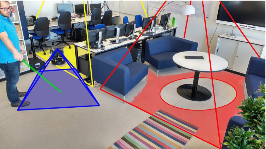
Addressing these shortcomings of the baseline approach, we propose the incorporation of additional smart home components in the interaction process as the answer to our first research question. This deals with the question of which sensors and actuators of the smart environment can be used to benefit the interaction process. Our proposed smart home environment is shown in Fig. 1 and mainly consists of three components: (1) a camera network comprising stationary RGB cameras, (2) a smart display and (3) a smart speaker allowing the processing of voice commands. The first component, i.e. the camera network, is intended to increase the perceptual capabilities in combination with the mobile robot’s on-board camera. Stationary cameras are integrated (yellow and red fields of view) to cover certain areas of the environment, while a mobile camera mounted on a robot (blue field of view) can observe areas that are not covered by the stationary cameras due to their installation or occlusions, e.g. under the table. Hence, this combination allows perception even if the stationary cameras do not cover all areas of the environment, which is typically the case in smart home environments. The second component, i.e. the smart display, is intended to provide expressive feedback to the user by visualizing the progress and result of the interaction process. Finally, it is the idea to employ a smart speaker to facilitate the change of different states of the interaction process using voice commands.
Fig. 1.
A person defines a virtual border in the environment using a laser pointer. The spot is observed by stationary cameras in the environment (yellow and red) and a mobile camera on a robot (blue). A smart display (top right) provides visual feedback of the complex spatial information, and a smart speaker facilitates interaction.
4.2.Human-robot-environment interaction
In order to achieve our objective of a reduced interaction time and increased user experience compared to the baseline approach, we propose a new interaction method leveraging the combination of a mobile robot and the described smart home environment in the interaction process. We denote this combination as network robot system (NRS) in the following. This interaction method is intended to answer our second research question of how to realize a cooperation of human, robot and smart environment in the interaction process. As pointed out in the introduction, the interaction process between human and robot (1) has to allow a transfer of spatial information from human to robot and (2) has to provide feedback about the interaction process from robot to human. The first property is addressed by allowing a user to specify virtual borders by “drawing” directly in the environment using a common laser pointer. A laser spot is cooperatively perceived by the stationary camera network and the mobile robot’s on-board camera.
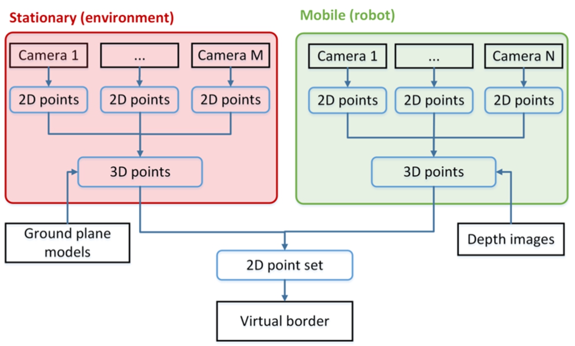
Fig. 2.
Architecture of the cooperative perception for specifying virtual borders based on multiple camera views.
The interaction method comprises several internal states, that reflect the three components of a virtual border as described in Section 3. The states are described as follows:
– Default: The NRS is in an inactive state and ignores all user interactions.
– Border: The NRS recognizes laser spots that are used to specify virtual border points
– Seed: The NRS recognizes laser spots and calculates the seed point
– Guide: This state is similar to the Default state, but the user can guide the mobile robot using the laser pointer without storing the laser spots. The state should be never reached if at least one of the stationary cameras’ fields of view covers a part of the restriction area and can send the mobile robot to this area. However, we incorporate this state into our interaction method to ensure its functionality in case of an absence of stationary cameras. In this case, a user has to manually guide the mobile robot to the restriction area because the robot cannot be automatically sent to the area due to missing information of the smart environment. Hence, the system degenerates to the baseline approach, i.e. a system without support of a smart home environment.
– Define border: This command is used to start the specification of virtual border points
– Define seed: This command is used to start the specification of a seed point
– Guide robot: The system’s internal state switches to Guide so that a user can guide the mobile robot using the laser pointer.
– Save: This command is employed when a user wants to integrate and save his or her user-defined virtual border into the map of the environment.
– Cancel: If a user does not want to save his or her user-defined virtual border, he or she can cancel the interaction process. Hence, the internal state changes to Default.
4.3.Cooperative perception
While the incorporation of the smart display and smart speaker in the interaction method is straightforward, the incorporation of the camera network, which is used to increase the interaction space, is more challenging. There are mainly two reasons: (1) multiple cameras, stationary and mobile, have to be integrated into an architecture that supports the interaction process and (2) a single virtual border has to be extracted from multiple camera observations including noisy data.
4.3.1.Architecture
Addressing the first aspect, we propose the architecture, that is illustrated in Fig. 2, as a first part of our answer to the third research question of how to cooperatively perceive and combine multiple camera observations to restrict the mobile robot’s workspace. The architecture consists of M stationary cameras integrated in the environment and N mobile cameras on mobile robots.22 Each camera independently performs laser point detection in image space resulting in a 2D point
4.3.2.Virtual border extraction
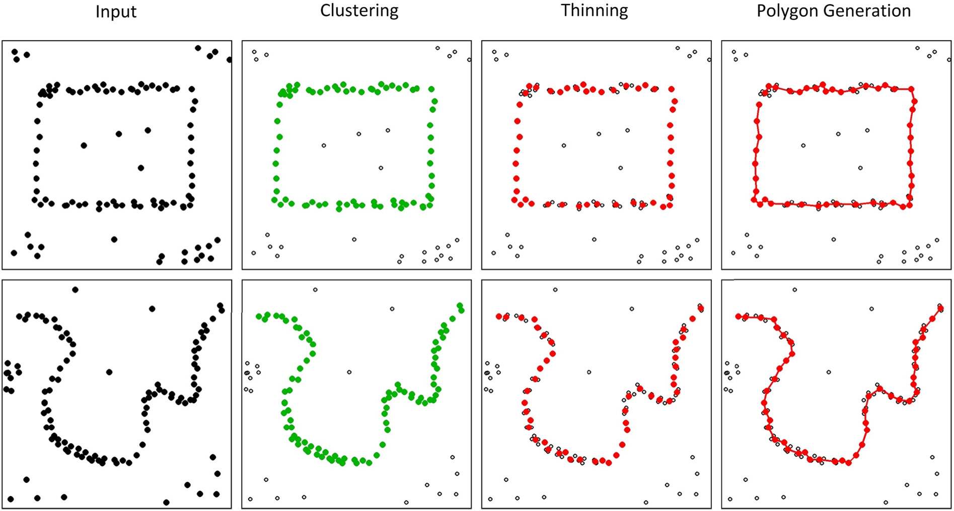
Fig. 3.
Processing stages extracting a polygonal chain from a point set including noise. Each row corresponds to a user-defined point set, a polygon in the first and a separating curve in the second row. The first column visualizes the input point set containing virtual border points but also noise and other clusters. The points assigned to the virtual border cluster are colored green in the second column. Thinning the virtual border cluster yields the red point set in column three. This is used to generate a polygonal chain as shown in the last column.
While the extraction of the seed point
Algorithm 1
Clustering step
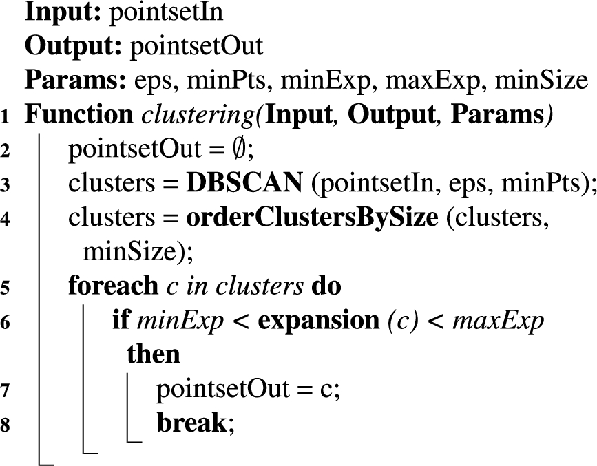
Clustering The first stage of the extraction algorithm is the clustering stage as denoted in Algorithm 1. The input is a 2D point set
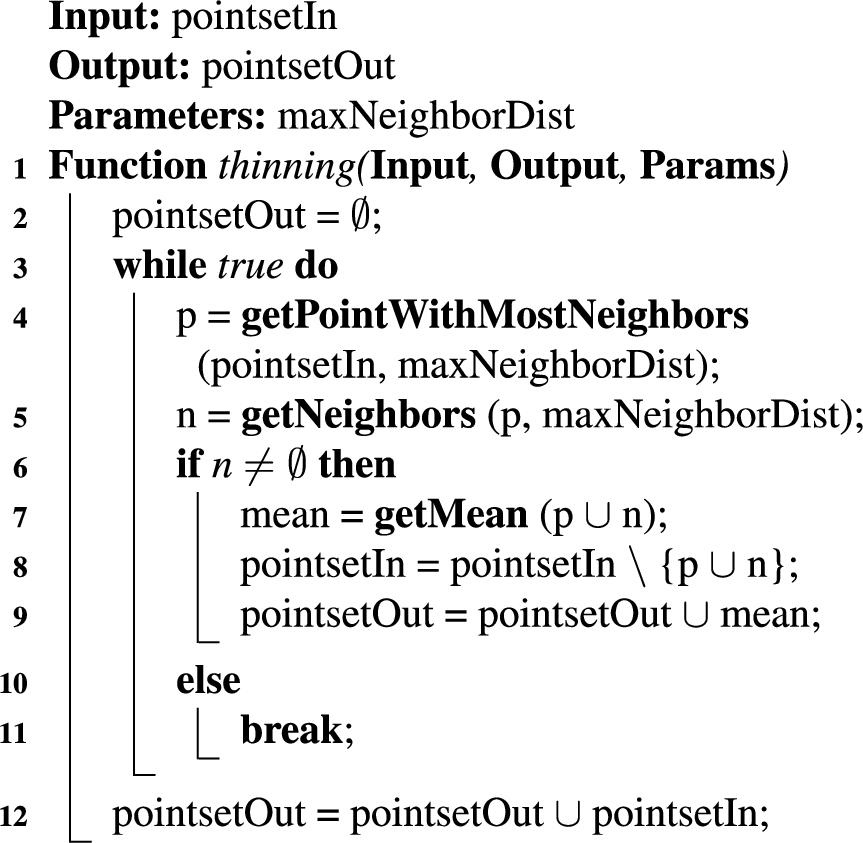
Thinning The second stage of the algorithm is the thinning stage (Algorithm 2), that reduces the number of points in the largest cluster from the previous stage. It is designed to remove spatially redundant data points and to smooth data points due to localization errors and calibration inaccuracies. Thus, it addresses the third and fourth challenge of the virtual border extraction step. For this purpose, the thinning algorithm identifies spatially nearby data points and replaces them by their mean value. To this end, the point p with most neighbors within a distance
Algorithm 2
Thinning step
Algorithm 3
Polygon generation step
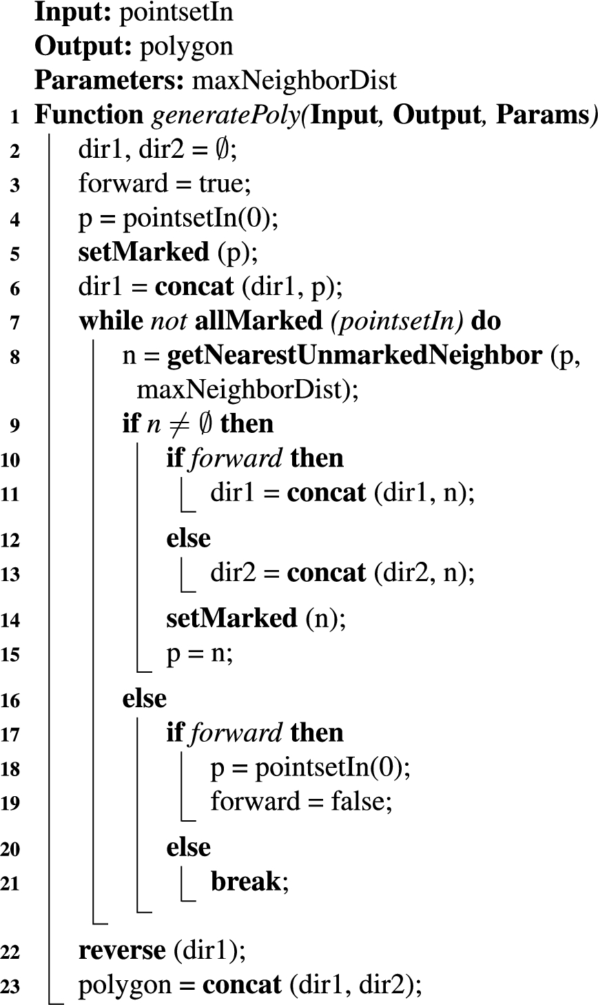
Polygon generation Finally, the thinned point set is the input
We use the parameter values shown in Table 1 for the algorithms. These were determined experimentally.
Table 1
Parameter values for the algorithms
| Stage | Parameter | Value |
| Clustering | eps | 0.5 m |
| minPts | 1 | |
| minExp | 0.3 m | |
| maxExp | ||
| minSize | 10 | |
| Thinning | maxNeighborDist | 0.1 m |
| Polygon generation | maxNeighborDist | 0.5 m |
5.Experimental evaluation
In order to evaluate our proposed interaction method and our hypotheses concerning user requirements, such as interaction time, user experience, completeness and accuracy, we conducted an experimental evaluation involving multiple participants and three scenarios for restriction areas in a smart home environment. The evaluation was inspired by the USUS framework, that provides a methodological framework to evaluate certain aspects of a system involving the interaction of human and robot [47].
5.1.Independent variables
In our experiment, we manipulated a single independent variable, i.e. the interaction method. This variable can have one of the two values:
1. Robot only: This is the baseline approach similar to Sprute et al. [46], that is based on sole HRI. A user interacts with the mobile robot by sketching the desired virtual border on the ground plane using a laser pointer. The mobile robot detects the laser spot employing its on-board camera and follows the laser spot using visual servoing technique if it attempts to leave the camera’s field of view [7]. In order to switch between different states of the interaction method, the user can push buttons on the backside of the robot or employ visual codes generated by the laser pointer. Feedback about the interaction method’s current state is provided through on-board colored LEDs and sound when switching between states. Additionally, beep tones are uttered when the system acquires virtual border points
2. Network robot system (NRS): This is our proposed approach based on a NRS described in Section 4. Additional to the mobile robot, the NRS features stationary cameras in the environment as additional sensors to perceive laser points. A voice control allows switching between system’s states using voice commands. Among colored LEDs and non-speech audio sound on board the mobile robot, a smart display integrated into the environment acts as additional feedback device. This shows a 2D OGM of the environment and the user-defined virtual borders.
5.2.Hypotheses
The objective of the experimental evaluation was the test of the following hypotheses:
– Hypothesis 1: Due to the extended perceptual capabilities, the interaction time is shorter when employing the NRS compared to the Robot only interaction method. We define the interaction time as the duration between the start, i.e. the first time employing the laser pointer, and the end of user interaction, i.e. the integration of the virtual border into the given map of the environment.
– Hypothesis 2: Due to the extended feedback and interaction capabilities, the user experience is better when employing the NRS compared to the Robot only interaction method. We define the user experience as a set of aspects concerning the interaction method, such as positive feeling, intuitiveness, demand, learnability and feedback.
– Hypothesis 3: The completeness does not significantly get worse when employing the NRS compared to the Robot only interaction method. We define the completeness as the success rate at which a user successfully completes an interaction process. We register a successful interaction process if a participant can correctly specify the virtual border points
– Hypothesis 4: The accuracy does not significantly get worse when employing the NRS compared to the Robot only interaction method. We define the accuracy as the overlap between the user-defined virtual border as the result of the interaction process and the user-intended virtual border as required by the experimental scenarios.
5.3.Setup
Fig. 4.
Image and 3D sketch of the lab environment. The three evaluation scenarios are numbered, and the three cameras’ fields of view are visualized in red, green and blue. The position of the smart display for feedback is encircled in red, and the mobile robot’s initial pose is depicted in the bottom right of the sketch.
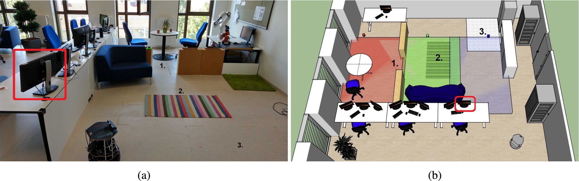
To test our hypotheses, we motivated our experimental setup by three scenarios for restriction areas as presented in the introduction, i.e. (1) privacy zones, (2) carpets and (3) dirty areas. For this purpose, we set up a home environment in our 8 m × 5 m lab environment comprising free space, walls, plants and furniture, such as tables and chairs. Additionally, we integrated adjustable walls with a height of 0.5 m to model two different rooms in the environment. Besides, we placed a carpet on the ground and some dirt in one area of the environment as basis for the evaluation scenarios. An image and 3D sketch of the environment is shown in Fig. 4.
As a mobile robotic platform, we employed a TurtleBot v2 equipped with a laser scanner for localization and a front-mounted RGB-D camera. This is a typical evaluation platform whose mobile basis is similar to a vacuum cleaning robot with differential-drive wheels. The camera’s color images were captured with a resolution of 640 × 480 pixels, and the depth sensor had a resolution of 160 × 120 pixels. Additionally, the robot had a colored on-board LED, three push buttons and a speaker. A prior OGM of the environment (2.5 cm per cell) was created beforehand using a Simultaneous Localization and Mapping (SLAM) algorithm running on the mobile robot [15], and the mobile robot was localized inside the environment using the adaptive Monte Carlo localization approach [13]. This allows the robot to determine its 3-DoF pose, i.e. position and orientation, with respect to the map coordinate frame.
In order to take advantage of a smart home environment as described in Section 4.1, we mounted three RGB cameras with an image resolution of
5.4.Procedure
After setting up the experimental environment, each participant was introduced to the following three evaluation scenarios. These scenarios covered both types of virtual borders and are good representatives for restriction areas:
1. Room exclusion: The user wants the mobile robot to not enter a certain room due to privacy concerns. For this purpose, the user draws a line separating the room from the rest of the environment. This area is in the fields of view of the red and green camera. The length of the polygonal chain
2. Carpet exclusion: The user wants the mobile robot to circumvent a carpet area (2.00 m × 1.25 m) while working. To this end, he or she draws a polygon around the carpet and specifies the inner area as restriction area. This area is in the fields of view of the green and blue camera.
3. Spot cleaning: The user wants his or her vacuum cleaning robot to perform a spot cleaning in a corner of a room. Hence, he or she draws a separating curve around the area and specifies the rest of the room as restriction area. This dirty area is indicated by paper snippets on the ground and is partly covered by the blue camera. The polygonal chain has a length of 3.60 m and encompasses an area of 3.20 m2.
In this experiment, we applied a within-subjects design, i.e. each participant evaluated both interaction methods in all three evaluation scenarios. The order of the selected interaction method was randomized to avoid order effects. After selecting an interaction method, an experimenter explained a participant how to employ the selected interaction method, i.e. a short introduction into the different states of the system, how to switch between states and how to use the laser pointer. Afterwards, a participant had some time to get familiar with the interaction device, i.e. the participant could use the laser pointer and guide the mobile robot. This took approximately five minutes. Subsequently, the participant started to specify virtual borders for the three scenarios. The order of the different scenarios was randomized. At the beginning of each scenario, the mobile robot’s initial pose was set to a predefined pose to allow the comparison between the results. This initial pose, that was not covered by a stationary camera, is shown in the bottom right of Fig. 4b.
The shortest paths to the restriction areas in the three scenarios were between 2.50 m and 5.40 m (Scenario 1: 5.40 m, Scenario 2: 2.50 m and Scenario 3: 3.00 m). Since we applied a within-subjects design, this procedure resulted in six runs per participant (three scenarios and two interaction methods) and a participant could compare both interaction methods. After performing the practical part of the experiment, each participant was asked to answer a post-study questionnaire concerning his or her user experience with the interaction methods. An experiment with a single participant took approximately 20 minutes in total.
5.5.Measurement instruments
During the experiment, the time needed to specify a virtual border for each participant, interaction method and scenario was measured. Thus, we obtained six measurements for each participant. The time measurement started with the change from the Default state to one of the active states and ended with the integration of the virtual border into the prior map. Moreover, the time measurement was decomposed according to the three active states of the system, i.e. guiding the mobile robot (
In addition to the time, an experimenter documented if a participant successfully specified a virtual border for an evaluation scenario, i.e. a participant could specify the virtual border points
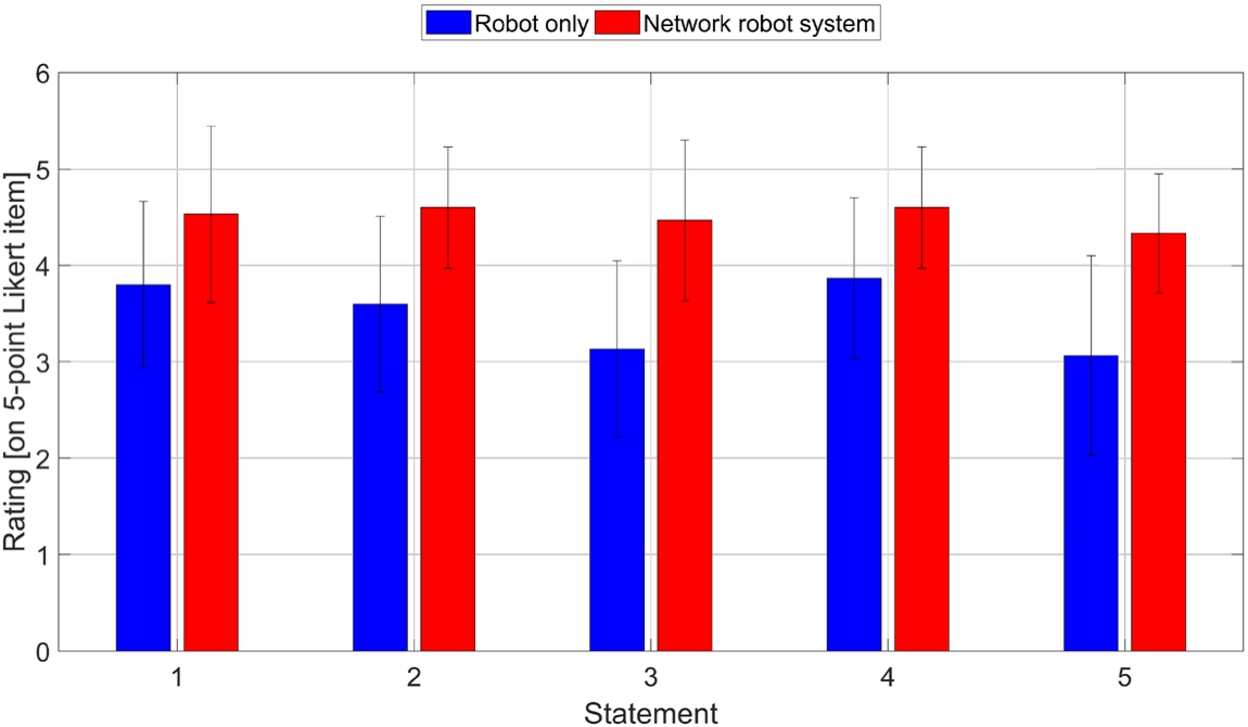
To measure the user experience, participants were asked to answer a post-study questionnaire. In addition to general information, such as age, gender and experience with robots, the questionnaire contained five statements concerning the user experience, that could be rated on 5-point Likert items with numerical response format. This questionnaire was inspired by the questionnaire of Rouanet et al., who used a similar questionnaire to assess the usability and user experience of human-robot interfaces [34]. The questionnaire included the following statements about the experiment (translated from German):
1. I had problems to define the virtual borders
(1 = big problems, 5 = no problems)
2. It was intuitive to define the virtual borders
(1 = not intuitive, 5 = intuitive)
3. It was physically or mentally demanding to define the virtual borders (1 = hard, 5 = easy)
4. It was easy to learn the handling of the interaction method (1 = hard, 5 = easy)
5. I liked the feedback of the system
(1 = bad/no feedback, 5 = good feedback)
The fourth evaluation criterion is the accuracy, that we assessed by calculating the Jaccard similarity index (JSI) between a user-defined UD and its associated ground truth GT virtual border:
5.6.Participants
The experiment was conducted with a total of 15 participants (11 male, 4 female) with a mean age of
5.7.Tools
We implemented all components of the system as ROS nodes [32]. ROS is a modular middleware architecture that allows communication between several components of a system, that are called nodes. ROS is the de facto standard for robot applications and provides a large set of tools to accelerate prototyping and error diagnosis. We organized all our nodes in packages to allow the easy distribution of our implementation. In order to save resulting maps of an interaction process for evaluation purposes, we implemented a node that directly stores the map on the hard disk whenever a new map is defined by a participant. Furthermore, we used integrated time functionality of ROS to perform time measurements for the evaluation. The visualization on the smart display was based on RVIZ, which is a 3D visualization tool for ROS.
5.8.Analysis & results
To test our hypotheses, we report the analysis and results of the experimental evaluation in this subsection. In case of statistical tests to identify differences between the interaction methods, we chose a significance level of
5.8.1.Interaction time
Fig. 5.
Interaction time for both interaction methods (blue and red contours around bars) based on the scenarios. Each bar is subdivided into the three active states of the system.
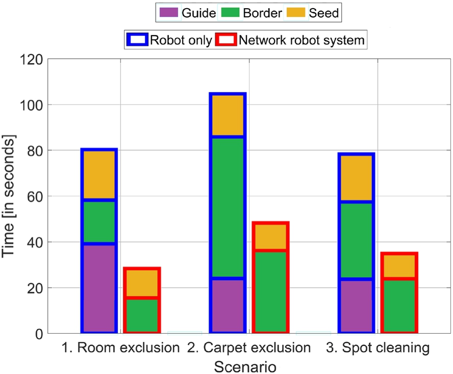
The interaction times of the experiment are summarized in Fig. 5. Each bar comprises the measurements of all 15 participants for an interaction method and scenario. Hypothesis 1 stated that the interaction time would be reduced when using the NRS compared to the Robot only interaction method. To test this hypothesis, we first ran Shapiro–Wilk tests to test for normality of the data (differences in the interaction times between the two interaction methods), which is an assumption of parametric statistical hypothesis tests, e.g. a paired t-test. These tests only became significant for the third scenario (
– 1. Room exclusion:
– 2. Carpet exclusion:
– 3. Spot cleaning:
Fig. 6.
User experience for both interaction methods showing mean and standard deviation depending on the statements.
The reason for this significant difference is revealed by the decomposition of the time measurements. While the time for the Robot only approach is composed of all active states of the system, our NRS approach does not include the Guide state. This is a consequence of the human-robot-environment interaction where the NRS automatically sends the mobile robot to the intended restriction area when a laser spot is detected by a stationary camera. Therefore, the user is not restricted to the mobile robot’s line of sight and does not have to manually guide the mobile robot to the intended restriction area. Thus, the NRS approach can avoid the time in the Guide state. This time primarily depends on the distance between the robot’s start pose and the restriction area. As described in Section 5.4, the distances in our scenarios ranged from 2.5 m to 5.4 m. If the distances would be smaller, the time in the Guide state would also decrease. However, we think that we chose the distances quite liberally since much larger distances would be even realistic, e.g. in typical home environments with a single charging station for the mobile robot.
Another reason for the time difference between the interaction methods is the time in the state Border, which is linear with respect to the border length [46]. Thus, if the user-defined virtual border is short, e.g. 0.70 m for Scenario 1, our NRS approach is only slightly faster in this state, i.e. 4 seconds difference. But if we consider a larger virtual border, e.g. the 6.50 m long border around the carpet (Scenario 2), our approach is even 26 seconds faster on average. The reason for this is the mobile robot’s velocity limitation (0.2 m/s) to ensure a safe and smooth movement of the robot. By using our NRS approach, this speed limitation can be reduced if the laser spot is in the field of view of one of the stationary cameras. Our interaction method is then only limited by the detection rate of the cameras (25 frames/s). Hence, it also features a linear interaction time, but with a smaller gradient.
Another speedup is achieved when specifying the seed point (Seed state) because a user can directly indicate the seed point with laser points, which are detected by a stationary camera. In case of the Robot only approach, a user additionally has to rotate the mobile robot around its vertical axis to adjust the camera’s field of view. This rotation takes additional interaction time. In summary, the results support Hypothesis 1.
5.8.2.User experience
In order to assess the user experience and test Hypothesis 2, i.e. the user experience is better when employing the NRS compared to the Robot only interaction method, we considered the participants’ answers of the questionnaire introduced in Section 5.5. The participants’ answers to the questionnaire are visualized in Fig. 6 with their mean (M) and standard deviation (SD) per statement and interaction method.
Since Likert-item data violate the assumption of normality, we ran a Wilcoxon signed-rank test on the 15 answers per statement to determine whether there are statistically significant differences between both interaction methods. We found statistically significant differences for all statements in the questionnaire:
– Statement 1:
– Statement 2:
– Statement 3:
– Statement 4:
– Statement 5:
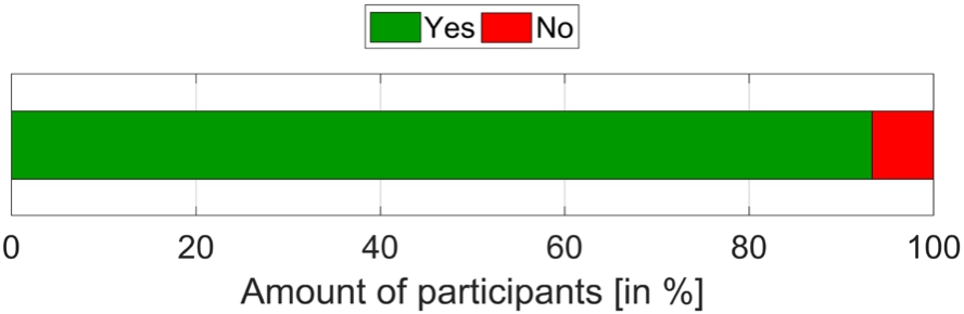
Fig. 7.
Answers of the participants to the question if the smart environment supported the interaction process.
5.8.3.Completeness
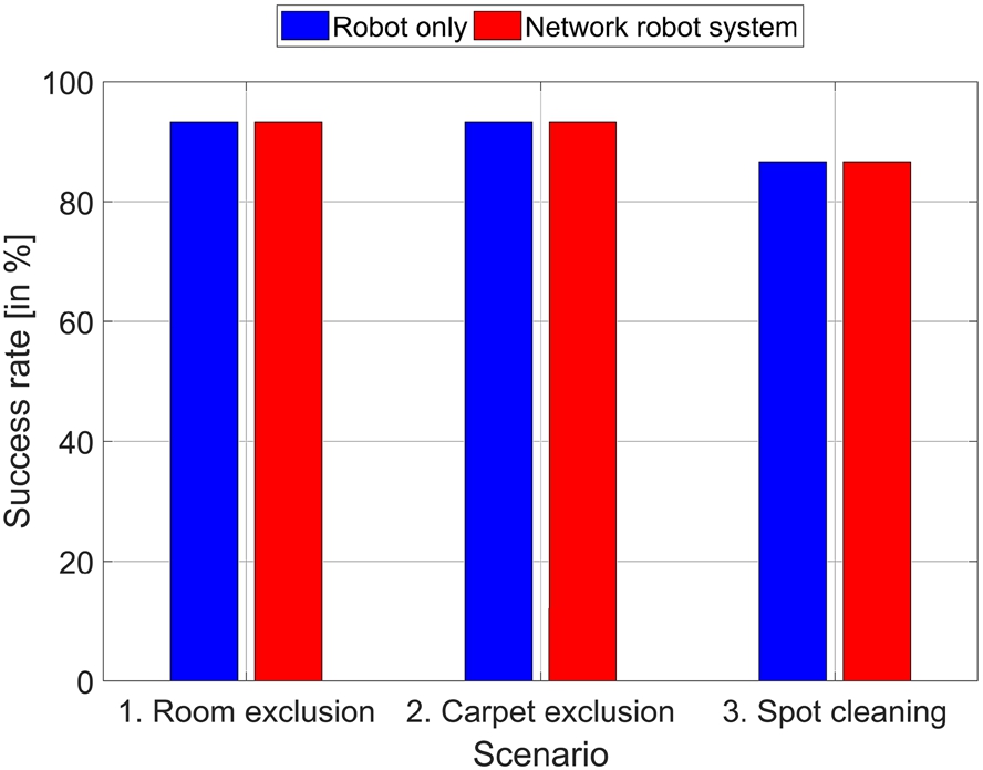
Hypothesis 3 stated that the completeness does not significantly get worse when employing the NRS compared to the Robot only interaction method. The success rates are summarized in Fig. 8 as bars. Both interaction methods feature the same high success rate, i.e. 91.1% on average. Furthermore, the success rates for the three scenarios are the same (93.3% for Scenarios 1 and 2; 86.7% for Scenario 3). There were nine participants who performed all their runs successfully, four participants who failed for one of their six runs, and two participants incorrectly defined a virtual border in two of their six runs. The reason for these incorrect runs was the definition of the seed point
Fig. 8.
Completeness for both interaction methods depending on the scenarios.
5.8.4.Accuracy
Fig. 9.
Quantitative accuracy results for both interaction methods depending on the scenarios.
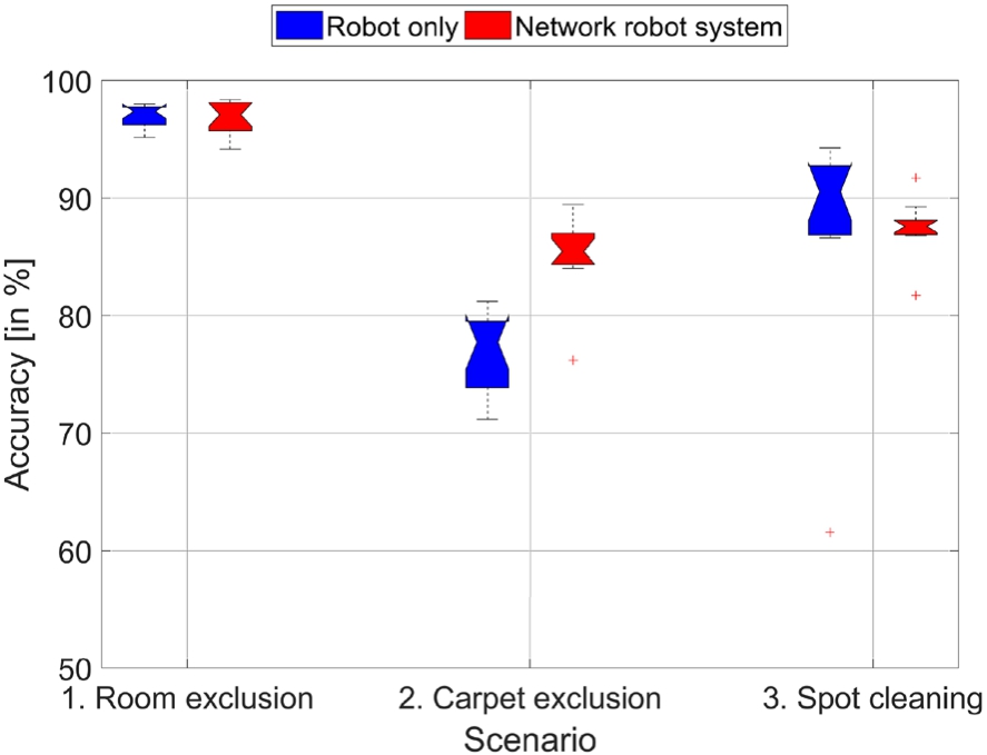
Fig. 10.
Visualization of representative accuracy results. The first row shows ground truth maps for all three scenarios containing occupied (black), free (white) and unknown (gray) areas. The yellow cells indicate the area to be specified by a participant during an interaction process (GT). The robot’s start pose is visualized as a red arrow. The following rows visualize the qualitative accuracy results for both interaction methods. A user-defined area as result of an interaction process is colored in green and red. Green pixels indicate the overlap of ground truth and user-defined areas (GT ∩ UD), while red pixels show areas defined by the user but not contained in the ground truth map (UD ∖ GT). A blue contour surrounds the union set of both areas (GT ∪ UD). Colors are only used for visualization.
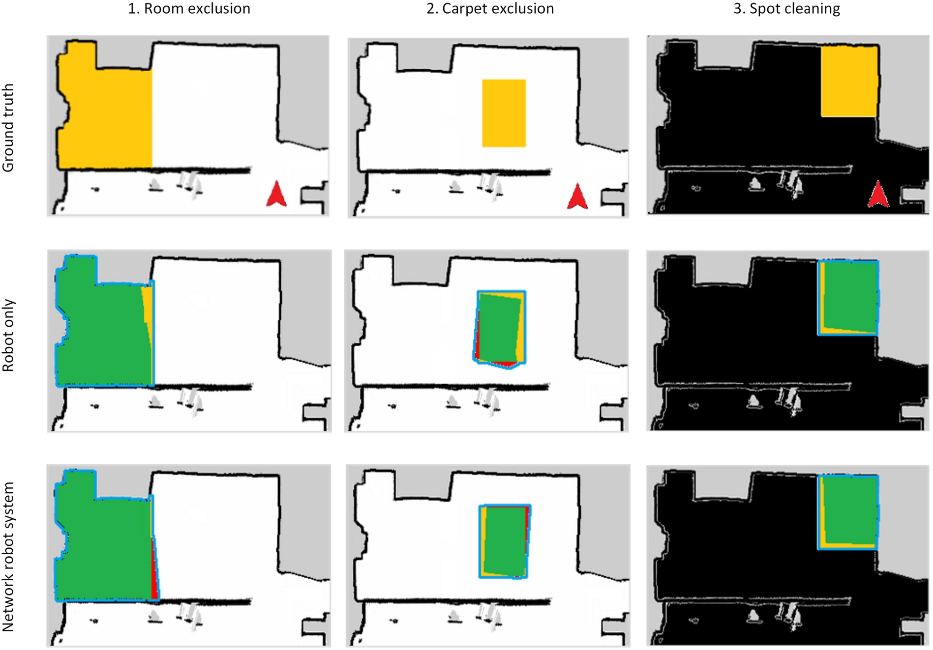
Finally, Hypothesis 4 stated that the accuracy does not significantly get worse when employing the NRS compared to the Robot only interaction method. The JSI values resulting from the experimental evaluation are presented in Fig. 9. To test the hypothesis, we again explored the data for normality and outliers using Shapiro–Wilk test and boxplot interpretation. The Shapiro–Wilk tests did not become significant for any scenario indicating a normal distribution of the data. However, since the data for Scenarios 2 and 3 contain some outliers, we preferred a Wilcoxon signed-rank test to a paired t-test. The statistical results were different for the three scenarios:
– 1. Room exclusion:
– 2. Carpet exclusion:
– 3. Spot cleaning:
5.9.Discussion
We designed our experimental evaluation according to the idea that the environment is partially observed by stationary cameras and that there are typical restriction areas, such as carpets or privacy zones. This is a typical setting for a smart home environment. In this case, our results suggest that a smart environment can significantly improve the interaction time (Hypothesis 1) and user experience (Hypothesis 2) while not negatively affecting the completeness (Hypothesis 3) and accuracy (Hypothesis 4).
However, there are two important aspects, that influence the speedup in the interaction time: (1) the stationary cameras’ coverage of the environment and (2) the distance between the mobile robot’s start pose and the restriction area. If we would decrease the number of cameras in the environment and thus the camera coverage, this would result in a smaller reduction of the interaction time. This would finally degenerate to the baseline approach if there is no camera coverage. Moreover, the speedup strongly depends on the distance between the mobile robot’s start pose and the restriction area, which influences the performance of the baseline approach. This is due to the fact that the baseline approach requires a direct line of sight between human and robot, and thus a human first has to guide the mobile robot to the restriction area. For these reasons, it is not possible to report a specific speedup value. Nonetheless, in the evaluation scenarios we chose a typical camera coverage and reasonable distances, which are typical for home environments with a single charging station for a mobile robot. Hence, we conclude that the interaction time improves with the support of a smart environment, but we cannot report a specific speedup value. Therefore, the reported speedups in Section 5.8.1 are intended to give an estimate and are only valid for this specific experimental evaluation.
In case of the user experience, participants appreciated aspects, such as a reduced mental or physical demand during interaction and an improved feedback of the system. These are effects of the incorporation of the smart environment’s components. However, a participant also wished an even stronger feedback system. The participant did not like the change of attention between the sketching of the virtual border on the ground and the view on the smart display, which was positioned aside on a table. Therefore, we conclude that our choice of smart home components improved the user experience significantly but the incorporation of more expressive feedback channels could improve the user experience even more.
6.Conclusions & future work
In this work, we investigated the effect of a smart home environment on the interaction process of restricting a mobile robot’s workspace. For this purpose, we developed a novel interaction method leveraging a smart home environment and laser pointer in the interaction process. This NRS was designed to support the interaction process in terms of perception and interaction abilities. To this end, we first selected smart home components that we employed to realize a cooperative behavior between human, robot and smart environment in the interaction process. Especially, the cooperative perception involving stationary and mobile cameras to perceive laser spots and an algorithm to extract virtual borders from multiple camera observations is a major contribution of this work. This cooperation between mobile robot and smart environment neutralized the mobile robot’s perceptual and interaction limitations. This was supported by an experimental evaluation that revealed an improvement of interaction time and user experience compared to a baseline method while preserving the high completeness and accuracy of the baseline. Hence, we conclude that a smart environment can improve the interaction process of restricting a mobile robot’s workspace.
Nonetheless, the experimental evaluation also revealed current limitations of this work. For example, a participant wished a stronger feedback system without change of attention between the restriction area on the ground and the map shown on the smart display. For this purpose, an augmented reality solution would be promising, e.g. projectors integrated into the smart environment could visualize the user-defined virtual borders directly on the ground without change of attention. Although there are already solutions in the industrial context [14,24], projectors are not yet widely distributed in current smart homes. Moreover, we currently evaluated our interaction method with a single mobile robot, which is valid for most households. However, it would be interesting to incorporate multiple robots into the interaction process to increase the number of mobile cameras. Our proposed architecture already considers this aspect (Fig. 2), but more work on the cooperation between multiple mobile robots in such a scenario is needed.
Notes
1 In this work, we only consider 100% to indicate occupied areas, but in the future this component could be used to model levels of restriction. For example, an occupancy of 75% could mean that a mobile robot should avoid this area unless it is necessary.
2 Although we consider a single mobile robot in this work, we designed the architecture with multiple mobile cameras due to scalability options in the future.
3 Although the median should be used to describe the central tendency in non-parametric tests, we report the mean value in this paragraph to better reveal the differences between the interaction methods. This is valid since we consider an interval-level of measurement [17]. Moreover, since other studies often report mean values for Likert-items, we also want to make our results better comparable.
Acknowledgement
This work is financially supported by the German Federal Ministry of Education and Research (BMBF, Funding number: 13FH006PX5). We would also like to thank all participants who took part in the experimental evaluation for their time and valuable feedback.
References
[1] | E. Ackerman, Neato Adds Persistent, Actionable Maps to New D7 Robot Vacuum, IEEE Spectrum (2017). |
[2] | F.K. Aldrich, Smart homes: Past, present and future, in: Inside the Smart Home, R. Harper, ed., Springer, London, (2003) , pp. 17–39. doi:10.1007/1-85233-854-7_2. |
[3] | N. Apthorpe, Y. Shvartzshnaider, A. Mathur, D. Reisman and N. Feamster, Discovering smart home Internet of things privacy norms using contextual integrity, Proceedings of the ACM on Interactive, Mobile, Wearable and Ubiquitous Technologies 2: (2) ((2018) ), 59–15923. |
[4] | J.C. Augusto, V. Callaghan, D. Cook, A. Kameas and I. Satoh, Intelligent Environments: A manifesto, Human-centric Computing and Information Sciences 3(12) (2013). |
[5] | K. Baraka and M.M. Veloso, Mobile service robot state revealing through expressive lights: Formalism, design, and evaluation, International Journal of Social Robotics 10: (1) ((2018) ), 65–92. doi:10.1007/s12369-017-0431-x. |
[6] | A. Butz, User interfaces and HCI for ambient intelligence and smart environments, in: Handbook of Ambient Intelligence and Smart Environments, H. Nakashima, H. Aghajan and J.C. Augusto, eds, Springer US, (2010) , pp. 535–558. doi:10.1007/978-0-387-93808-0_20. |
[7] | F. Chaumette, S. Hutchinson and P. Corke, Visual servoing, in: Springer Handbook of Robotics, B. Siciliano and O. Khatib, eds, Springer International Publishing, (2016) , pp. 841–866. doi:10.1007/978-3-319-32552-1_34. |
[8] | T.-Y. Chiu, Virtual wall system for a mobile robotic device, 2011, European Patent Application EP000002388673A1. |
[9] | M. Cirillo, L. Karlsson and A. Saffiotti, Human-aware task planning: An application to mobile robots, ACM Transactions on Intelligent Systems and Technology 1: (2) ((2010) ), 1–26. doi:10.1145/1869397.1869404. |
[10] | P. Corke, Mobile robot vehicles, in: Robotics, Vision and Control: Fundamental Algorithms in MATLAB, Springer, Berlin Heidelberg, (2011) , pp. 65–86. doi:10.1007/978-3-642-20144-8_4. |
[11] | N.T. Djaid, S. Dourlens, N. Saadia and A. Ramdane-Cherif, Fusion and fission engine for an assistant robot using an ontology knowledge base, Journal of Ambient Intelligence and Smart Environments 9: (6) ((2017) ), 757–781. doi:10.3233/AIS-170458. |
[12] | M. Ester, H.-P. Kriegel, J. Sander and X. Xu, A density-based algorithm for discovering clusters a density-based algorithm for discovering clusters in large spatial databases with noise, in: Second International Conference on Knowledge Discovery and Data Mining, (1996) , pp. 226–231. |
[13] | D. Fox, Adapting the sample size in particle filters through KLD-sampling, The International Journal of Robotics Research 22: (12) ((2003) ), 985–1003. doi:10.1177/0278364903022012001. |
[14] | R.K. Ganesan, Y.K. Rathore, H.M. Ross and H. Ben Amor, Better teaming through visual cues: How projecting imagery in a workspace can improve human-robot collaboration, IEEE Robotics & Automation Magazine 25: (2) ((2018) ), 59–71. doi:10.1109/MRA.2018.2815655. |
[15] | G. Grisetti, C. Stachniss and W. Burgard, Improved techniques for grid mapping with Rao-blackwellized particle filters, IEEE Transactions on Robotics 23: (1) ((2007) ), 34–46. doi:10.1109/TRO.2006.889486. |
[16] | B. Gromov, G. Abbate, L. Gambardella and A. Giusti, Proximity human-robot interaction using pointing gestures and a wrist-mounted IMU, in: IEEE International Conference on Robotics and Automation (ICRA), (2019) . |
[17] | S.E. Harpe, How to analyze likert and other rating scale data, Currents in Pharmacy Teaching and Learning 7: (6) ((2015) ), 836–850. doi:10.1016/j.cptl.2015.08.001. |
[18] | N. Hawes, C. Burbridge, F. Jovan, L. Kunze, B. Lacerda, L. Mudrova, J. Young, J. Wyatt, D. Hebesberger, T. Kortner, R. Ambrus, N. Bore, J. Folkesson, P. Jensfelt, L. Beyer, A. Hermans, B. Leibe, A. Aldoma, T. Faulhammer, M. Zillich, M. Vincze, E. Chinellato, M. Al-Omari, P. Duckworth, Y. Gatsoulis, D.C. Hogg, A.G. Cohn, C. Dondrup, J.P. Fentanes, T. Krajnik, J.M. Santos, T. Duckett and M. Hanheide, The STRANDS project: Long-term autonomy in everyday environments, IEEE Robotics & Automation Magazine 24: (3) ((2017) ), 146–156. doi:10.1109/MRA.2016.2636359. |
[19] | K. Ishii, S. Zhao, M. Inami, T. Igarashi and M. Imai, Designing laser gesture interface for robot control, in: Human-Computer Interaction – INTERACT 2009, (2009) , pp. 479–492. doi:10.1007/978-3-642-03658-3_52. |
[20] | K. Kang, X. Lin, C. Li, J. Hu, B.J. Hengeveld, C.C.M. Hummels and G.W.M. Rauterberg, Designing interactive public displays in caring environments: A case study of OutLook, Journal of Ambient Intelligence and Smart Environments 10: (6) ((2018) ), 427–443. doi:10.3233/AIS-180504. |
[21] | C.C. Kemp, C.D. Anderson, H. Nguyen, A.J. Trevor and Z. Xu, A point-and-click interface for the real world: Laser designation of objects for mobile manipulation, in: Proceedings of the 3rd ACM/IEEE International Conference on Human Robot Interaction, (2008) , pp. 241–248. |
[22] | B.M. Kim, S.S. Kwak and M.S. Kim, Design guideline of anthropomorphic sound feedback for service robot malfunction – with emphasis on the vacuum cleaning robot, in: IEEE International Symposium on Robot and Human Interactive Communication, RO-MAN, (2009) , pp. 352–357. |
[23] | J.H. Kim, K.H. Lee, Y.D. Kim, N.S. Kuppuswamy and J. Jo, Ubiquitous robot: A new paradigm for integrated services, in: Proceedings 2007 IEEE International Conference on Robotics and Automation, (2007) , pp. 2853–2858. doi:10.1109/ROBOT.2007.363904. |
[24] | F. Leutert, C. Herrmann and K. Schilling, A spatial augmented reality system for intuitive display of robotic data, in: 2013 8th ACM/IEEE International Conference on Human-Robot Interaction (HRI), (2013) , pp. 179–180. |
[25] | R. Li, M.A. Oskoei and H. Hu, Towards ROS based multi-robot architecture for ambient assisted living, in: 2013 IEEE International Conference on Systems, Man, and Cybernetics (SMC), (2013) , pp. 3458–3463. doi:10.1109/SMC.2013.590. |
[26] | K. Liu, D. Sakamoto, M. Inami and T. Igarashi, Roboshop: Multi-layered sketching interface for robot housework assignment and management, in: SIGCHI Conference on Human Factors in Computing Systems, (2011) , pp. 647–656. |
[27] | J. Minguez, F. Lamiraux and J.-P. Laumond, Motion planning and obstacle avoidance, in: Springer Handbook of Robotics, B. Siciliano and O. Khatib, eds, Springer International Publishing, (2016) , pp. 1177–1202. doi:10.1007/978-3-319-32552-1_47. |
[28] | H. Moravec and A. Elfes, High resolution maps from wide angle sonar, in: IEEE International Conference on Robotics and Automation (ICRA), (1985) , pp. 116–121. |
[29] | Neato, What are boundary markers and how do I use them? 2019, Online access: 07/19, https://support.neatorobotics.com/hc/en-us/articles/225370067-What-are-boundary-markers-and-how-do-I-use-them-. |
[30] | N.S.M. Nor and M. Mizukawa, Robotic services at home: An initialization system based on robots’ information and user preferences in unknown environments, International Journal of Advanced Robotic Systems 11: (7) ((2014) ), 112. doi:10.5772/58682. |
[31] | Y. Pyo, K. Nakashima, S. Kuwahata, R. Kurazume, T. Tsuji, K. Morooka and T. Hasegawa, Service robot system with an informationally structured environment, Robotics and Autonomous Systems 74: (Part A) ((2015) ), 148–165. doi:10.1016/j.robot.2015.07.010. |
[32] | M. Quigley, K. Conley, B. Gerkey, J. Faust, T.B. Foote, J. Leibs, R. Wheeler and A.Y. Ng, ROS: An open-source robot operating system, in: ICRA Workshop on Open Source Software, (2009) . |
[33] | R. Rasch, D. Sprute, A. Pörtner, S. Battermann and M. König, Tidy up my room: Multi-agent cooperation for service tasks in smart environments, Journal of Ambient Intelligence and Smart Environments 11: (3) ((2019) ), 261–275. doi:10.3233/AIS-190524. |
[34] | P. Rouanet, P.Y. Oudeyer, F. Danieau and D. Filliat, The impact of human-robot interfaces on the learning of visual objects, IEEE Transactions on Robotics 29: (2) ((2013) ), 525–541. doi:10.1109/TRO.2012.2228134. |
[35] | R.B. Rusu, B. Gerkey and M. Beetz, Robots in the kitchen: Exploiting ubiquitous sensing and actuation, Robotics and Autonomous Systems 56: (10) ((2008) ), 844–856. doi:10.1016/j.robot.2008.06.010. |
[36] | A. Saffiotti, M. Broxvall, M. Gritti, K. LeBlanc, R. Lundh, J. Rashid, B.S. Seo and Y.J. Cho, The PEIS-ecology project: Vision and results, in: 2008 IEEE/RSJ International Conference on Intelligent Robots and Systems, (2008) , pp. 2329–2335. doi:10.1109/IROS.2008.4650962. |
[37] | A. Sandygulova, M. Dragone and G.M. O’Hare, Privet – a portable ubiquitous robotics testbed for adaptive human-robot interaction, Journal of Ambient Intelligence and Smart Environments 8: (1) ((2016) ), 5–19. doi:10.3233/AIS-150356. |
[38] | A. Sanfeliu, N. Hagita and A. Saffiotti, Network robot systems, Robotics and Autonomous Systems 56: (10) ((2008) ), 793–797. doi:10.1016/j.robot.2008.06.007. |
[39] | S. Shibata, T. Yamamoto and M. Jindai, Human-robot interface with instruction of neck movement using laser pointer, in: IEEE/SICE International Symposium on System Integration (SII), (2011) , pp. 1226–1231. |
[40] | P. Simoens, M. Dragone and A. Saffiotti, The Internet of Robotic Things: A review of concept, added value and applications, International Journal of Advanced Robotic Systems 15(1) (2018). doi:10.1177/1729881418759424. |
[41] | D. Sprute, A. Pörtner, R. Rasch, S. Battermann and M. König, Ambient assisted robot object search, in: 15th International Conference on Smart Homes and Health Telematics (ICOST), (2017) , pp. 112–123. |
[42] | D. Sprute, R. Rasch, A. Pörtner, S. Battermann and M. König, Gesture-based object localization for robot applications in intelligent environments, in: 2018 International Conference on Intelligent Environments (IE), (2018) , pp. 48–55. doi:10.1109/IE.2018.00015. |
[43] | D. Sprute, R. Rasch, K. Tönnies and M. König, A framework for interactive teaching of virtual borders to mobile robots, in: 2017 26th IEEE International Symposium on Robot and Human Interactive Communication (RO-MAN), (2017) , pp. 1175–1181. doi:10.1109/ROMAN.2017.8172453. |
[44] | D. Sprute, K. Tönnies and M. König, Virtual borders: Accurate definition of a mobile robot’s workspace using augmented reality, in: 2018 IEEE/RSJ International Conference on Intelligent Robots and Systems (IROS), (2018) , pp. 8574–8581. doi:10.1109/IROS.2018.8593615. |
[45] | D. Sprute, K. Tönnies and M. König, A study on different user interfaces for teaching virtual borders to mobile robots, International Journal of Social Robotics 11: (3) ((2019) ), 373–388. doi:10.1007/s12369-018-0506-3. |
[46] | D. Sprute, K. Tönnies and M. König, This far, no further: Introducing virtual borders to mobile robots using a laser pointer, in: IEEE International Conference on Robotic Computing (IRC), (2019) , pp. 403–408. |
[47] | A. Weiss, R. Bernhaupt, M. Lankes and M. Tscheligi, The USUS evaluation framework for human-robot interaction, in: Symposium on New Frontiers in Human-Robot Interaction, (2009) , pp. 158–165. |
[48] | M. Ziefle, S. Himmel and W. Wilkowska, When your living space knows what you do: Acceptance of medical home monitoring by different technologies, in: Information Quality in e-Health: Conference of the Workgroup Human-Computer Interaction and Usability Engineering of the Austrian Computer Society (USAB), (2011) , pp. 607–624. doi:10.1007/978-3-642-25364-5_43. |


