
Assessment of five control strategies of an adjustable glazing at three different climate zones
Abstract
The energy demand for operating modern office spaces is often driven by either the annual heating demand, cooling demand or the demand for electrical lighting. The irradiation of the sun directly and indirectly affects the demand of all three. Consequently, the glazing of higher office buildings is often treated with coating that allows a fixed transmittance. Due to changing exterior conditions and interior needs, a fix-transmittance value is a compromise and most often doesn’t provide optimal thermal and visual conditions. The team in the research project named Fluidglass develops a new glazing in which the transmittance of the glazing can be adjusted. This is possible by colouring a fluid, which is circulated in chambers of the glazing. The concentration of the colorant can be infinitely adjusted. In addition, this window allows collecting heat in the exterior fluid and allows the interior fluid chamber to operate as heating panel. This paper presents a first assessment of different control strategies for adjusting the colorant concentration with a simplified model. The assessed control strategies result in considerably different overall energy demands. Certain control strategies have high potential for reducing the energy demand for heating and cooling depending on the locations (Munich 20–30% , Madrid 50–70% , Dubai 50–60%). However, certain control strategies increase the electricity demand for lighting, which needs to be considered in the further development. In general, control strategies that only consider the solar irradiation are less promising strategies in temperate climate than strategies that also take the interior temperature into account. The results of controls that also respect the thermal comfort based on a Predicted Mean Vote (PMV) index can achieve low energy demand, presuming that a deviation from the highest level of comfort is acceptable. At this stage of research, none of the studied control strategies shows to be optimal for all climate conditions to achieve highest energy reductions. Further research is necessary in the development of a control strategy that can universally be applied.
1Background
The driving idea of this research project is developing an adaptive glazed facade element that allows controlling the solar transmittance within the glazing element to benefit from higher solar heat gains when needed during the cold season and to reduce solar heat gain during the hot season while ensuring enough daylight (Stopper, 2013). Up to now, the technologies used to achieve adjustable transparency are electro-chromic materials, liquid crystals and electrophoretic or suspended-particle devices (Baetens et al., 2010). In addition to those technologies, the technology used in this research project allows adjusting the concentrations of a colorant in a fluid that is circulated in a chamber between two panes of glass, which affects the solar transmittance. The basic idea of this project is shown in the diagram of Figure 1, which is adding panes of glasses to the exterior and interior face of a regular triple glazing to create the necessary fluid chambers. Contrary to regular solar glazing, the glass used in this configuration should allow for maximal transmittance, as the solar transmittance is adjusted by the according fluid chambers. The LowE coating on the glasses towards the inert gas fillings is required to achieve high thermal resistance. The coating is not required in terms of solar irradiation. A laminated safety glass is required in the centre to ensure safety. The overall dimension of this configuration, which is called Fluidglass, is about 60 mm, which will require an adjusted framing. In addition, a configuration with only one fluid chamber will also be assessed in this research project.
The fluid chambers (FCe and FCi) are each 2 mm wide. Fluid (water plus additives) is circulated in the chambers. Heat is transferred between fluid and interior or exterior space. A heat exchanger is connected to each circuit, which allows connecting the fluid circuit to the regular building heating and cooling system, as shown with the diagrams in Figure 3. The fluid in the two chambers is operated separately. Antifreeze is added to the fluid of the exterior chamber. Adjusting the temperature and mass flow rate of the fluid inlet affects the efficiency of the exterior fluid chamber as solar thermal collector and the interior fluid chamber as panel heating and cooling respectively. The mass flow rate varies between 1 to 3 kg·min–1 per running meter of Fluidglass. Since the hydrostatic pressure of the fluid in the fluid chamber would damage the glass, the fluid is set to negative pressure. This requires spacers to keep the minimal distance between the panes of glasses, as shown in the sketch of Figure 2. Nozzle bands at top and bottom of the glazing ensure a laminar flow. Furthermore, Fluidglass requires a so-called Fluid circuit box, which contains a separator and a dispenser. These components adjust the required concentration of the colorant in the fluid, as shown in Figure 3. (Gstoehl et al., 2011).
2Operation modes
The considered configuration allows operating the Fluidglass in different modes, depending on the location, the time of the day and the installed building system. The basic modes are shown in Figure 4. The transmittance of the facade facing the sun can be adjusted during the summer day to ensure that minimal illuminance is provided, but overheating is avoided (as shown in Figure 4 top left). The first prototype proves that changing the concentration of the particles in the fluid of the chamber can be achieved quickly, which allows reacting quickly to changes of the solar irradiation due to clouds etc. This layer also acts as solar thermal collector, especially if the concentration of the colorant is high. Collected heat can be used to support space heating directly or indirectly as heat source for a heat pump system, to generate hot potable water, for regenerating thermal energy storages like boreholes or in district heating networks. At locations with high solar irradiation and exterior temperatures, heat gains generated in the exterior fluid chamber (FCe) reduce the interior cooling demand. If the building cooling system is able to store this collected heat during daytime and to release it during the night, instead of releasing it to the ambient with a chiller right away, the energy demand for cooling is expected to decrease, as the temperature of the heat sink during night-time is lower than during daytime. This could be realized by circulating the heated fluid during the night in the exterior fluid chamber (as shown in Figure 4, top right). The fluid in the chamber facing the interior (FCi) can be operated during the hot season as cooling panel by circulating a fluid with low temperature. During the cold season, the exterior fluid chamber (FCe) is less often operating as solar thermal collector (as shown in Figure 4, bottom left). Solar heat gains are collected directly in the interior space. The interior fluid chamber (FCi) acts during this season as heating panel. During spring and autumn, when the solar irradiation is already relatively high in combination with a solar altitude close to the horizon, unwanted interior solar heat gains can cause overheating in modern office spaces. Consequently, the shading system is active on the critical windows (as shown in Figure 4, bottom right). The gained heat surplus can be transferred for heating in other parts of the building that are not directly exposed to the solar irradiation. The fluid inlet temperature and the mass flow rate define the power of the panel. During the hot season, the interior fluid chamber panel is circulated with cold fluid for cooling the interior space with inlet temperatures of 18°C, while the fluid inlet temperature is raised to 30°C during the cold season for heating. This allows for a cooling power of 50 W·m–2 per pane of glass and for a heating power of 70 W·m–2 respectively. Certainly, the heating power can further be increased with higher inlet temperature, but increasing the cooling power with lower inlet temperature than 18°C would risk condensation at the glass panel. Typical modern office spaces are built with large areas of glazing. The large areas of glass allow panel heating and cooling with temperatures relatively close to the room temperature. This is an important criterion for operating buildings with renewable energies (e.g. heating and cooling with ground water or geothermal heat exchangers). In general, a surface area of the glazed facade closer to the temperature of other components of the building (floor, ceiling, interior walls) also reduces the imbalance of long wave radiation in the space and raises the thermal comfort of the user.
3Method
The full potential of the Fluidglass can only be assessed in a dynamic building simulation. Fluidglass allows controlling the following five parameters: inlet fluid temperature and mass flow rate of the interior fluid chamber (FCe) and inlet fluid temperature, mass flow rate and colorant concentration of the exterior fluid chamber (FCe). The model developed for the first analysis, is designed in TRNSYS 17. The model allows comparing the annual energy demand of a generic office space when controlling the concentration of the colorant of Fluidglass in comparison to a reference case with a typical glazing. The results of the annual heating and cooling demands and the electricity demand for lighting are based on an ideal system at three different locations: Munich to represent a cold-temperate climate condition, Madrid to represent a hot-temperate climate condition and Dubai to represent a subtropical climate condition.
The model focuses on the colorant concentration in the exterior fluid chamber. It is assumed that the inlet fluid temperatures and mass flow rates of both chambers are operated in ideal mode. In particular, it is assumed that the interior mass flow rate and temperature will always be adjusted so that the required heating or cooling demand will be reached, which is an assumption of an ideal heating and cooling element that is only limited by the previously mentioned maximal cooling power of 50 W·m–2 of pane of glass and maximal heating power of 70 W·m–2. In addition, it is assumed that the mass flow rate and inlet temperature of the exterior fluid chamber are set to allow for efficient heat gains. Obviously, this needs to be assessed more in detail in following studies, which are currently in design stage.
The model space is set up according to the reference space described in the technical standard VDI 2078:2012-03, which reflects an office space of 17.5 m2, as shown in Figure 5. This model space is further differentiated in terms of thermal mass with five classes, varying from extremely heavy (indicated with XH) to extremely light (indicated with XL). Besides the fully glazed vertical facade that is orientated to the South, all remaining walls, floor and ceiling are designed to be adiabatic. The overall heat transfer coefficient of the glazing in all models is 0.7 W·m–2·K–1 at standard reference conditions. The area of the frame equals 15% of the overall opening, which has an overall heat transfer coefficient of 2.3 W·m–2·K–1.
The transmittance of the Fluidglass configuration with clear fluid in the fluid chambers is calculated in the software Optics6 and Window7.2. Relatively low concentrations of the colorant in the exterior fluid chamber (FCe) affect the visual and solar transmittance already quite considerable. The visual and the solar transmittance of the colorant change proportionally with rising concentration of the colorant as shown in Figure 6. The visual transmittance always stays above the solar transmittance, which is beneficial for the visual comfort.
The internal load is set according to DIN 4108-2:2013-02 (DIN 2013) with 13 W·m–2 representing the load from user, appliances and lighting. Further settings for infiltration and ventilation are also according to this standard, with typically an air exchange rate (including infiltration) of 1/h if users are present and a rate of 0.24/h if users are absent. The model also includes a mode with increased ventilation rate of 3/h representing night cooling during the hot season.
The reference model is identical to the model described above, besides the type of glazing. This model is equipped with solar glazing that has a solar transmittance of Tsol = 0.177 in combination with a visual transmittance of Tvis = 0.436. Furthermore, the overall heat transfer coefficient of the glazing with 0.7 W·m–2·K–1 matches the heat transfer coefficient of the Fluidglass at standard reference conditions. The electricity demand for lighting is in all considered cases based on the assumption that six fluorescent light bulbs are required to illuminate the space, which cause a power demand of 13.7 W per square meter office space. Table 1 shows the SHGC and Tvis according to the angle of incidence.
It is planned to realize windows with the dimensions of 1.5 m width by 3.0 m height. The weight of 80 kg per square meter for the Fluidglass version with two fluid chambers requires a reinforcement of the framing, especially in the corners. Furthermore, the overall thickness of the glazing package with 60 mm is at the limit that can be inserted in standard profiles from the consortium partner Alcoa.
4Settings of the control strategies
The model allows comparing five control strategies of the colorant concentration. The nature of rule based control strategies is to be reactive and not predictive. Each control strategy is active the entire year. In general, all control strategies set the concentration of the colorant to maximum if the interior air temperature, Tint, rises above 25°C, since first approximation regarding the cooling power of the Fluidglass indicates that this power is limited and cannot provide enough cooling for the considered office space if low transmittance allows high solar irradiation to overheat the space during the hot season.
The solar irradiation is key parameter of the first control strategy (CS1). The standard DIN 4108-2:2013-02 provides recommendations for simulating shading controls for office spaces. According to this standard, shading is required if solar radiation exceeds 200 W·m–2 global irradiation on the glazing. The purpose of this is to avoid overheating during the hot season. However, this strategy sets the colorant concentration to a maximal or minimal set point.
The second control strategy (CS2) sets the colorant concentration based on the illuminance in the interior space. According to DIN 15251:2007, a minimal interior illuminance of 500 Lux is required at the centre of the space on working desk level to guarantee comfortable working conditions. Simulations with the software ReLux-Pro show that minimal illuminance of 1700 Lux is required directly behind the Fluidglass to allow for the required 500 Lux at the working desk level (Böing, 2013). Depending on the colorant concentration, this level of illuminance is reached at different levels of solar irradiation. While 26 W·m–2 are enough if the fluid of the Fluidglass is uncoloured, more than 258 W·m–2 are required if the concentration of the colorant is 3% . Table 2 lists the colorant concentrations at the resulting Tsol and Tvis that ensure the required 500 Lux.
The disadvantage of CS1 and CS2 is that the interior air temperature, which accounts for the heating and cooling demand, is at best indirectly considered. This is taken into account in the third strategy (CS3), where the colorant concentration is gradually changed with the rising interior air temperature [Tint]. This ensures that solar irradiation generates interior heat gains if the room temperature is below the benchmark of 21°C, but also reduces the solar irradiation gradually if higher temperatures are reached. The colorant concentration is set to maximum if Tint exceeds 25°C. This, however, also reduces the visual transmittance considerably. At days with low solar irradiation and high concentration of the colorant in the fluid of the Fluidglass, electrical lighting is required to ensure 500 Lux interior illuminance at the centre of the space at the height of a work desk. Table 3 lists the controls of the colorant concentration and the according transmittances.
The fourth control strategy (CS4) aims for high level of thermal comfort. This is provided by controlling the Predicted Mean Vote index (PMV) which P.O. Fanger has developed (Fanger, 1970). This index complies with ANSI/ASHRAE Standard 55 (ASHRAE, 2013). The PMV is a measurement for the thermal sensation, given as PMV-Index. The PMV-Index is scaled by a seven point psycho-physical scale, ranging from –3 to +3. Negative values indicate the thermal sensation as too cold, positive values as too warm and the zero point as neutral. The PMV-Index is calculated by the PMV-equation, which is more or less an energy balance of the human body. The control strategy CS4 allows a deviation of the PMV in the range of –0.2 to +0.2. Presuming this is provided, the colorant concentration is chosen based on Tint, as shown in Table 4. If the PMV exceeds the benchmark +0.2 or falls below –0.2, the colorant concentration is set to 0% to allow for maximal solar heat gains.
The fifths control strategy (CS5) is basically the same as the control strategy CS4; besides this control aims for medium level of thermal sensation by allowing for a PMV ranging from –0.5 to +0.5. Table 4 lists the criteria of control CS4 and CS5.
Besides reducing the cooling demand, the purpose of the exterior fluid chamber FCe is to operate as solar thermal collector. The efficiency of this collector depends on the concentration of the colorant. A separate model has been developed with the software EES to calculate the outlet temperature of this fluid chamber. Based on the temperature differences between fluid outlet and inlet, the efficiency of the exterior fluid chamber as collector is determined. This information is used within TRNSYS as input for the simulation of an unglazed solar thermal collector. The model calculates the heating and cooling demand based on ideal building systems with maximal efficiency. It is assumed that a hot water tank exists in the building that allows storing the daily gained heat from the Fluidglass collector, which is used for reducing the daily space heating demand. This is a simplification of real heating systems.
Electrical power is also required for circulating the fluid in the interior fluid chamber for heating and cooling, but also in the exterior fluid chamber for shading. This power demand will be compared to the power demand required for operating a heating/cooling panel in the reference case. The concentration of the anti-freeze in cold climate is 30% Vol, which equals a density of 1040 kg/m3. With a height of 3 m and a hydraulic efficiency of 0.77 and electrical efficiency of 0.9 of the auxiliary pumps, the electricity demand is roughly 0.75 W, which is a simplification that only reflects peak demand. More relevant are pressure losses that the nozzle bands and other elements within the fluid circuit cause (e.g. heat exchanger, pumps, etc). Measurements at the prototype show that the total power demand is about 18 W. The power is multiplied with the number of hours the exterior and interior fluid is circulated in the chamber to determine the energy demand shown in Figure 7 and Figure 8 in purple.
5Results
In a first step, the assessment shows that different thermal mass of the five building types of the reference case result at the three considered locations in considerably different annual useful energy demand for heating and cooling, as shown in Figure 7. The building type ‘XL’ denotes an extremely light building, while the type ‘XH’ denotes a building that is extremely heavy. In between is the building type ‘M’ that denotes a building with medium thermal mass. While rising thermal mass is beneficial in the cold- and warm-temperate climate of Munich and Madrid, high thermal mass is counterproductive at locations like Dubai, where stored heat in the building mass is less often possible to be released by night cooling etc. The electricity demand for lighting is generally lower at hotter locations.
Accordingly, the location and building type affects the results of the simulations with the Fluidglass model. In the following chapter, the results of the control strategies are only shown for the building type M, because the results of the other building types basically follow the same trend. The bar diagrams in Figure 8 show the annual useful heating demand, cooling demand for space heating and electricity demand for lighting the space for the type M, which is referred to as reference case (Ref) for each control strategy (CS).
Already the simple rule based strategy (CS1), which only considers the solar irradiation, results in lower energy demand. Although the total energy demand is lower than that of the reference case, this strategy considerably reduces the cooling demand, but increases slightly the heating demand. The second control strategy (CS2) gradually increases the colorant concentration according to the solar irradiation instead of setting the colorant concentration to maximal at 200 W·m–2 as in the first control strategy (CS1). The result of the CS2 shows that the cooling demand in Madrid and Dubai can further be reduced, but this strategy also increases the heating demand in Munich and Madrid slightly. A more successful strategy regarding the reduction of the heating and cooling demand is the third strategy (CS3). Considering the interior temperature as the relevant control value increases the possibility to benefit from passive heat gains during the cold season. This strategy increases the number of days with low colorant concentration in the exterior Fluidglass chamber, which allows for more solar radiation to pass during the cold season. Although CS3 is more successful in terms of the cooling demand in Madrid and Dubai, this strategy is less optimal at these locations compared to CS2 in terms of electricity demand for lighting. Operating the Fluidglass with CS3, there are more days during the hot season where the interior temperature Tint exceeds the critical 25°C and the colorant concentration reaches maximum. As a result, the number of hours increases when electrical lighting is required, especially in Dubai. Consequently, controlling the colour concentration based on the solar radiation is a more successful strategy at these locations.
The fourth and fifths control strategy (CS4 and CS5) generate similar results at the location Munich and Madrid compared to CS3. Allowing for a medium comfort with the CS5 even results in the lowest total of the heating and cooling demand. However, the electricity demand for lighting cannot considerably be reduced compared to CS3. The results with CS4 at the location Dubai are even the worst of all considered strategies. Although the control strategy CS5 allows for the lowest cooling demand, this strategy cannot considerably reduce the electricity demand for lighting.
6Conclusions
This paper studies a new type of glazing, which is titled Fluidglass. This glazing allows circulating fluid in chambers of the glazing. Increasing the concentration of a colorant can change the transmittance of the glazing. The studied models set the colorant concentration according to different control strategies. As expected, the control strategy considerably determines the success of the Fluidglass element. This paper only studies the effect that changing the colorant concentration of the exterior Fluid chamber has on the heating, cooling and electricity demand for lighting. Other controls of this new type of glazing, which are fluid inlet temperatures and mass flow rate, have not been studied. In general, the results of the studied control strategies show that Fluidglass can reduce the cooling and heating demand at all three different locations compared to a reference building with good solar glazing.
In particular, Fluidglass has great potential to reduce the cooling demand in a hot climate. A reduction of the overall heating and cooling demand of about 50% seems possible in Madrid and Dubai without considerably increasing the electricity demand for lighting. However, Fluidglass will require additional electricity for pumping power for circulating the fluid. While no antifreeze will be required in the fluid of the exterior fluid chamber in hot climate, some concentration of antifreeze will be necessary at locations like Madrid, where exterior temperatures below 0°C are possible. Next assessments will take into account that the viscosity also affects the power demand. Certain control strategies further reduce the cooling demand but simultaneously increase the electricity demand for lighting and pumping considerably. This is mainly because of the limited cooling power of the fluid glass, which requires to increase the colorant concentration of the exterior fluid chamber to maximum to ensure that the interior temperature can be kept below 26°C. As a result, the number of hours where electrical lighting is required increases. Consequently, next studies will focus on more optimal control strategies in a hot climate with the following improvements: first, due to the limited cooling power of the Fluidglass, additional cooling components are accepted, which will presumable allow for lower concentration of the colorant and as a result will reduce the electricity demand for lighting. Second, it is currently assumed that the lighting can only be turned on or off. The following models will allow for diming the lighting according to the minimum needs.
In addition, Fluidglass has certain potential to reduce the heating demand compared to the reference model. At best the heating demand at the location in Munich is reduced by 20% . The major unknown factor is the actual efficiency of the exterior fluid chamber in terms of heat gains. Since the collector efficiency of the Fluidglass is very complex to calculate, a prototype has been built in this research project and will be assessed during the following months to allow for more precise simulations. Furthermore, the heating system designed for this model uses the heat gains from the collector directly for space heating, which is a simplification of real systems. In the following studies, the heating system will be designed to allow storing heat for more than one day. In addition, a heat pump system will be implemented in the models that allow using the heat gain from the collector as heat source. It is expected that especially during the milder and colder season in the temperate climate of Munich the latter improvements to the models will affect the energy demand for heating.
In summary, the following models will allow to determine more precisely the heat gains of the exterior fluid chamber, the electricity demand for lighting, the electricity demand for auxiliary pumps and the electricity demand of the heat pumps system. This will allow balancing the energy reduction in cooling and heating demand with potentially rising electricity demand for electricity demand. In addition, changing the solar transmittance of the glazing will affect visual transmittance. Consequently, the next assessment of control strategies will not only focus on low energy demand, but on a higher level of comfort, aiming for an adjustable facade system that allows for an optimal operation to serve the actual needs of the user.
Acknowledgments
The team of this research project is a consortium of research institutes in Austria, Cyprus Czech Republic, France, Germany and Switzerland. We thank all partners within the Fluidglass project for supporting this paper and working on the development of this new type of glazing. A complete list of partners can be found online on the website www.fluidglass.eu. We thank the European Union for gratefully supporting this project with by the Seventh Framework Programme for Research and Technological Development and Demonstration Activities (FP7) under grant agreement No. 608509. The project is scheduled until September 2017.
References
1 | ASHRAE Standard Committee (2013). ASHRAE HANDBOOK: Fundamentals 2013. |
2 | Baetens R, Jelle BP, Gustavsen A (2010) Properties, requirements and possibilities of smart windows for dynamic daylight and solar energy control in buildings: A state-of-the-art review Solar Energy Materials & Solar Cells 87 105 |
3 | Böing F (2013) Energiebilanzierung eines Raumes mit fluiddurchströmten Glasfassadenelementen Bachelor Thesis Technical University of Munich |
4 | Fanger PO (1970) Thermal comfort. Analysis and applications in environmental engineering Thermal comfort. Analysis and applications in environmental engineering Copenhagen, Denmark Danish Technical Press |
5 | Gstoehl D, Stopper J, Bertsch S, Schwarz D (2011) Fluidised glass facade elements for an active energy transmission control World Engineers’ Convention Geneva |
6 | Stopper J, Böing F, Gstoehl D (2013) Fluid Glass Façade Elements: Energy Balance of an Office Space with a Fluid Glass Façade Proceedings of the Conference sb13 Munich - Implementing Sustainability - Barriers and Chances Munich |
Figures and Tables
Fig.1
Diagram of a section of the currently considered configuration of Fluidglass in mm. green = pane of glass, blue = fluid in fluid chambers, dashed red = LowE coating, grey = inert gas filling (krypton), VSG = laminated safety glass. VSG= laminated safety glass.
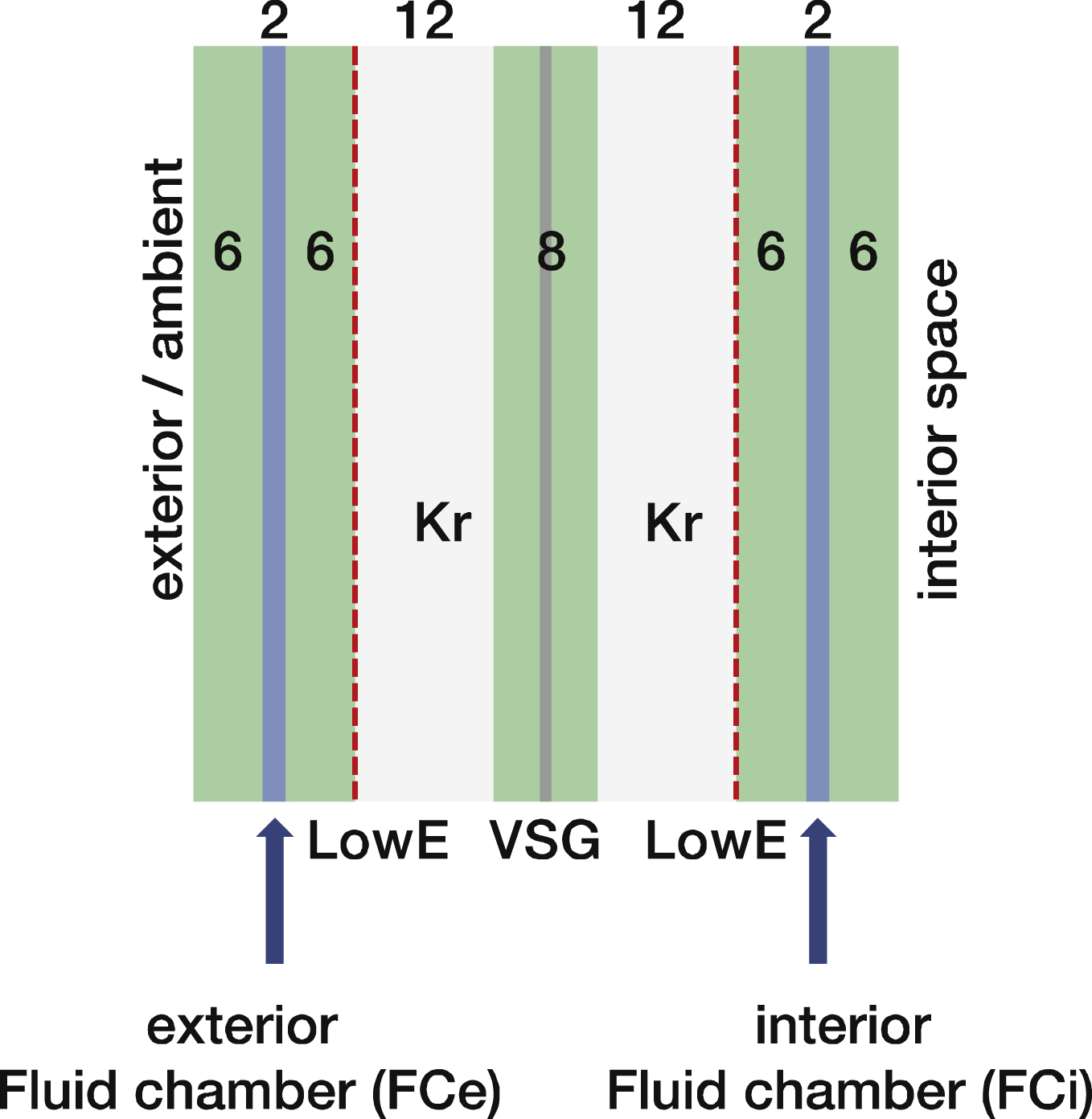
Fig.2
Section of the currently considered components of Fluidglass, showing the nozzle bands at top and bottom, four inlets and four outlets and the required spacers to keep the distance between the pane of glasses.
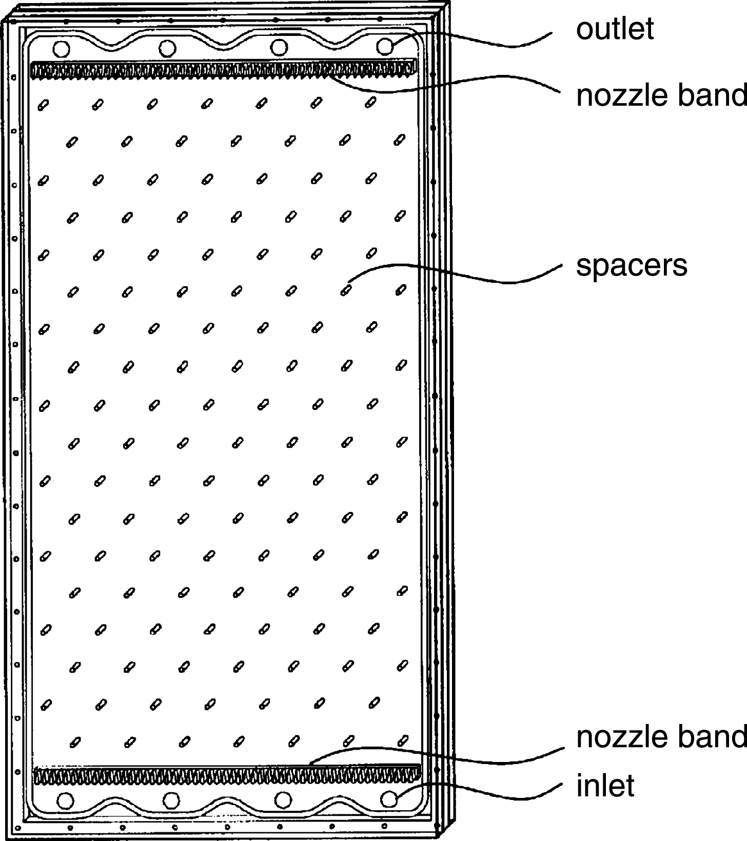
Fig.3
Diagram of the Fluidgass facade element, showing the glazing and the fluid circuit box (illustration on the left) and the Fluidglass facade connected to the building HVAC core system on the right.
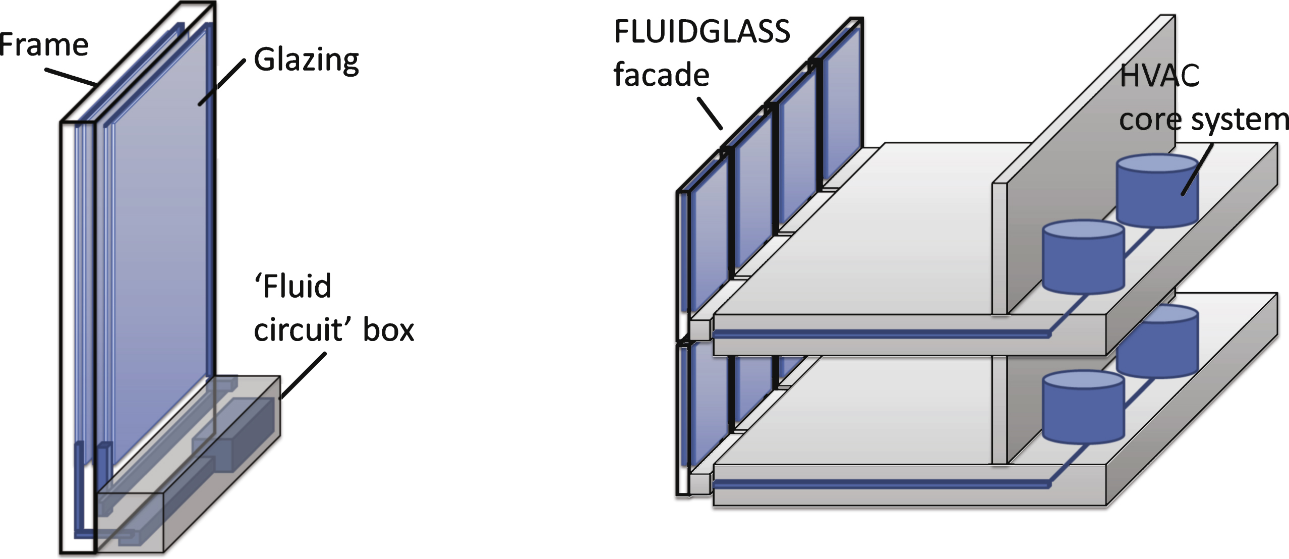
Fig.4
Schematic of the basic operation modes of Fluidglass. High concentration of particles in the exterior fluid chamber prevents from overheating during the summer day (top left), while minimal concentration of particles during the winter day allows for high internal heat gains (bottom left). Heat surplus can be transferred to the ambient during the night (top right). Medium concentration of particles in fluid allows for optimal conditions during the seasons in between (bottom right).
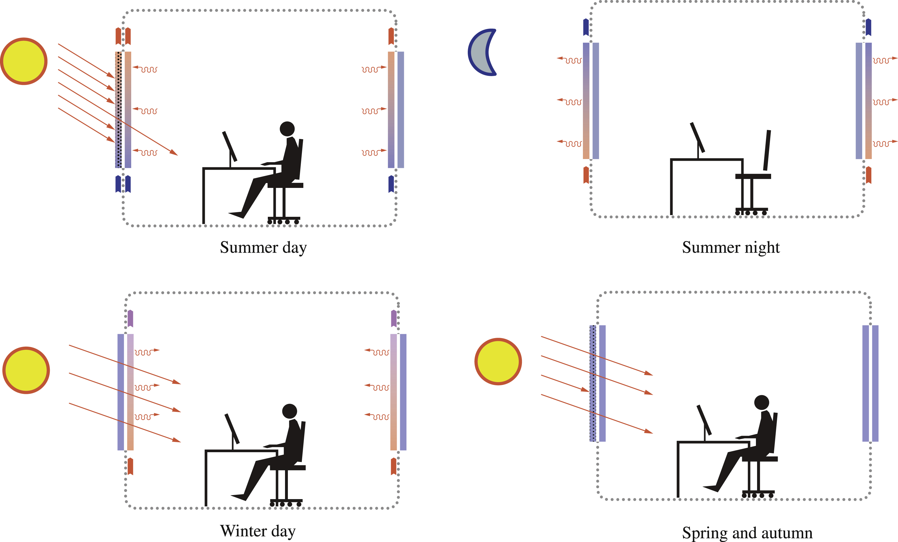
Fig.5
Schematic of the model space used in the simulation.
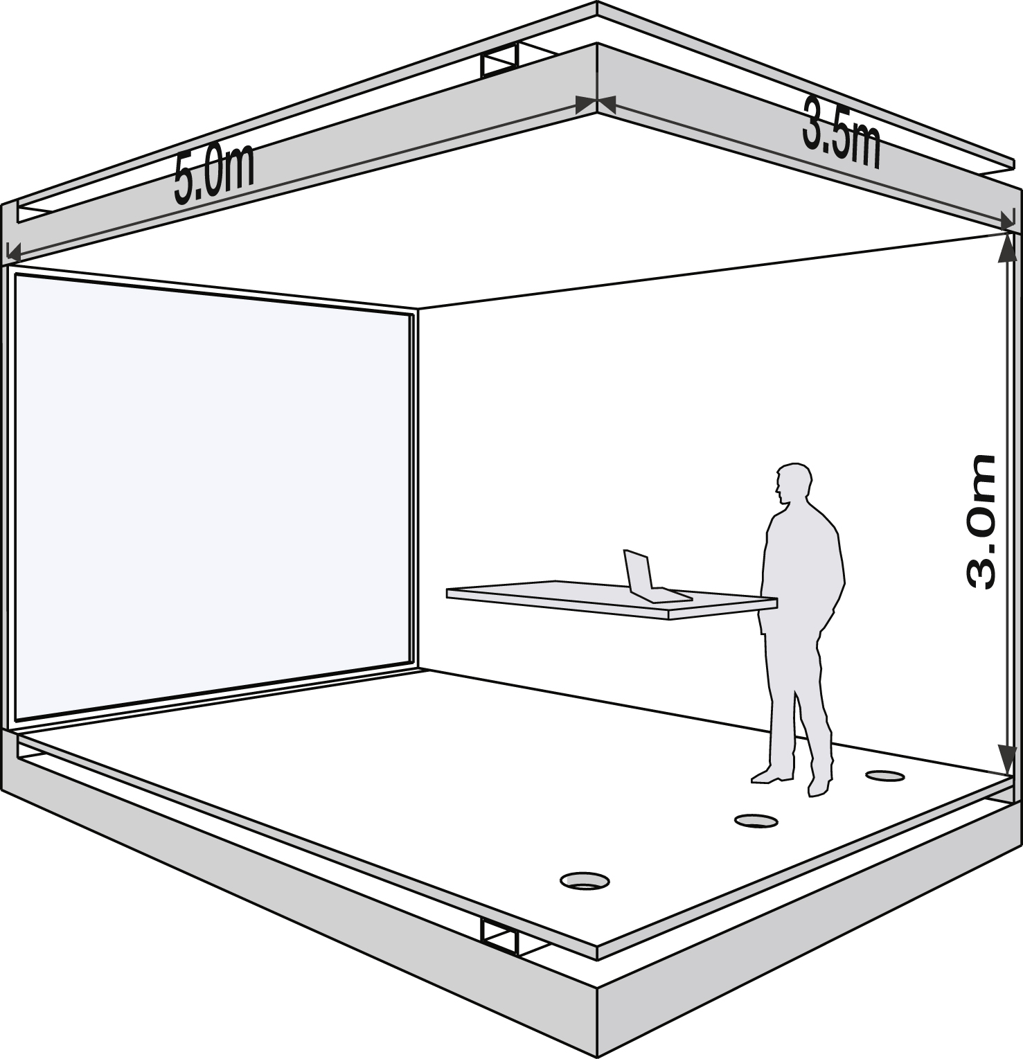
Fig.6
Tsol and Tvis of the studied colorant product at different concentration in percentage of the solution.
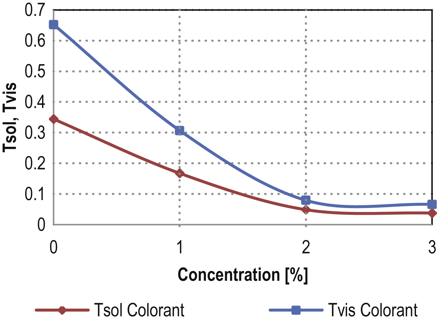
Fig.7
Resulting annual useful energy demand [kWh/m2] for heating, cooling, electrical energy demand for lighting and auxiliary pumps of the reference building with solar glazing (Tsol = 0.177) in Munich, Madrid and Dubai for extremely light (XL), light (L), medium (M), heavy (H) and extremely heavy (XH) buildings.
![Resulting annual useful energy demand [kWh/m2] for heating, cooling, electrical energy demand for lighting and auxiliary pumps of the reference building with solar glazing (Tsol = 0.177) in Munich, Madrid and Dubai for extremely light (XL), light (L), medium (M), heavy (H) and extremely heavy (XH) buildings.](https://content.iospress.com:443/media/fde/2015/3-2/fde-3-2-fde0036/fde-3-2-fde0036-g007.jpg)
Fig.8
Resulting annual useful energy demand [kWh/m2] of heating, cooling and electrical energy demand for lighting and auxiliary pumps, generated with the different control strategies (CS1 to CS5) compared to the reference building (Ref) of the building type M in Munich, Madrid and Dubai.
![Resulting annual useful energy demand [kWh/m2] of heating, cooling and electrical energy demand for lighting and auxiliary pumps, generated with the different control strategies (CS1 to CS5) compared to the reference building (Ref) of the building type M in Munich, Madrid and Dubai.](https://content.iospress.com:443/media/fde/2015/3-2/fde-3-2-fde0036/fde-3-2-fde0036-g008.jpg)
Table 1
SHGC and Tvis of the reference case
| Angle | 10 | 20 | 30 | 40 | 50 | 60 | 70 | 80 | 90 |
| Tvis | 0.436 | 0.438 | 0.433 | 0.427 | 0.415 | 0.391 | 0.337 | 0.236 | 0.095 |
| SHGC | 0.222 | 0.222 | 0.221 | 0.220 | 0.218 | 0.215 | 0.206 | 0.178 | 0.105 |
Table 2
Benchmarks of the second control strategy, controlled by the solar radiation [I0]
| I0 >26 W m–2 | I0 >55 W m–2 | I0 >214 W m–2 | I0 >258 W m–2 | |
| Colorant concentration | 0% | 1% | 2% | 3% |
| Solar transmittance Tsol [-] | 0.34 | 0.17 | 0.05 | 0.04 |
| Visual tansmittance Tvis [-] | 0.65 | 0.31 | 0.09 | 0.07 |
Table 3
Benchmarks of the third control strategy, controlled by the interior air temperature [Tint]
| Tint < = 23°C | Tint >23°C | Tint >24°C | Tint >25°C | |
| Colorant concentration | 0% | 1% | 2% | 3% |
| Solar transmittance Tsol [-] | 0.34 | 0.17 | 0.05 | 0.04 |
| Visual tansmittance Tvis [-] | 0.65 | 0.31 | 0.09 | 0.07 |
Table 4
Colorant concentrations for the control strategy CS4 and CS5, combining interior air temperature [Tint] and solar radiation [I0], presuming the PMV index is within the according range of –0.2 to +0.2 for CS4 and within the range of –0.5 to 0.5 for CS5
| Presuming PMV within range of –0.2…+0.2 with CS4 and of –0.5…+0.5 with CS5 | I0 >26 W·m–2 | I0 >55 W·m–2 | I0 >214 W·m–2 | I0 >258 W·m–2 |
| Tint >25°C | 3% | 3% | 3% | 3% |
| Tint = 22°C … 25°C | 0% | 1% | 2% | 3% |
| Tint <22°C | 0% | 0% | 0% | 0% |

