
Simulation and experimental study on rope driven artificial hand and driven motor
Abstract
BACKGROUND:
Prosthetic hands have the potential to replace human hands. Using prosthetic hands can help patients with hand loss to complete the necessary daily living actions.
OBJECTIVE:
This paper studies the design of a bionic, compact, low-cost, and lightweight 3D printing humanoid hand. The five fingers are underactuated, with a total of 9 degrees of freedom.
METHODS:
In the design of an underactuated hand, it is a basic element composed of an actuator, spring, rope, and guide system. A single actuator is providing power for five fingers. And the dynamic simulation is carried out to calculate the motion trajectory effect.
RESULTS:
In this paper, the driving structure of the ultrasonic motor was designed, and the structural size of the ultrasonic motor vibrator was determined by modal and transient simulation analysis, which replace the traditional brake, realize the lightweight design of prosthetic hand, improve the motion accuracy and optimize the driving performance of prosthetic hand.
CONCLUSIONS:
By replacing traditional actuators with new types of actuators, lightweight design of prosthetic hands can be achieved, improving motion accuracy and optimizing the driving performance of prosthetic hands.
1.Introduction
The hand is one of the most powerful limbs of the human body, with the strongest flexibility and the ability to complete various daily tasks. In many areas, many people have lost this important limb due to various reasons, such as congenital causes, diseases, and unpredictable accidents. The loss of upper limbs will seriously damage an individual’s work skills, social skills, and activities of daily living, and the consequences are even devastating for individuals and families [1, 2]. Patients urgently need a kind of equipment to replace their hands and help them return to normal life [3, 4]. It is necessary to use artificial hands to meet this demand.
As the most important part of the upper limb movement structure, the hand has 27 bones, 21 degrees of freedom, and 3 muscles. Sports involve a rather high level of dexterity. The muscle structure that drives them is also extremely complex. Many artificial hands imitate its structure and pursue similar functions. The performance of the artificial hand includes grasping characteristics, natural movement, shape adaptability, contraction movement, workspace, etc. Based on the various functions and degrees of freedom of fingers, the artificial hand is still an unsolved challenge in the field of robotics [5, 6, 7, 8].
To use robots to realize these functions, researchers have developed many dexterous humanoid robots [9, 10]. To perform the effective grasping movement, many effective robot hands with adaptive grasping or a low degree of freedom have been developed. The representative core mechanisms of the dexterous robot hand can be divided into direct motor drive, tendon drive, linkage drive, and shape memory alloy (SMA) drive [11, 12, 13, 14, 15, 16].
The Prosthetic hand was developed based on the motor direct drive mechanism, finger joint positioning motor, and direct-drive joint. This structure has high joint driving efficiency, and the joint position is easy to arrange. Dong-Hyuk Lee designed a humanoid robot hand named “KITECH-Hand”, analyzed its kinematics, and described its mechanical characteristics in detail [17]. Through kinematics analysis, the author found that the KITECH hand showed very high flexibility, far exceeding the existing robot hand with traditional MCP joints. The unique MCP structure also helps to modularize the robot at the joint level, which simplifies its mechanical structure and reduces the production cost. However, the number of hand joints is too large, and the total use of motor will lead to the overall weight of the prosthetic hand, the increased inertia, and it is difficult to control. At the same time, it will lead to the narrow movement space and the difficulty of the overall circuit connection.
The artificial hand driven by connecting rod has high firmness, easy manufacture and maintenance, high output force, and strong stability, and the joint can move in the desired direction through a structure [18]. The prosthetic bionic hand-designed by Chao wang is named BitHand C. To make the hand as light as possible, it is designed with aluminum alloy, nylon, rubber, and other materials. Its total mass is only 332 g, driven by five motors, and it has the characteristics of small size, high precision, and self-locking [19]. Wooseok Ryu can make a compact design by using two four-bar linkages composed of linkages and gears to couple the joints at each finger, and the linkages have advantages such as accurate positioning, uniform power transmission, and high payload. In addition, by using the constant speed joint, the torque will be transmitted to the finger module regardless of the adduction/abduction movement [20]. Kyung Yun Choi proposed a flexible four-bar mechanism to make the fingers of the prosthetic hand more impact-resistant. The rigid input and coupler links are replaced by flexible bones, and the driven links are replaced by prestressed springs. Compared with the traditional four-bar linkage, the designed finger absorbs 11% more energy during impact without mechanical failure [21]. However, the connecting rod is relatively thick and hard, so it is difficult to realize multi-degree-of-freedom movement and keep a large working space.
The tendon-driven prosthetic hand is the most similar to the muscle drive of the human hand, which can realize the movement similar to that of the human hand. According to the connection mode of the tendon, it is easy to generate higher fingertip force, and it is easy to realize the lightweight design [22, 23, 24]. Elif Hocaoglu designs underactuated compliant fingers with tendon drive, which allows the natural adaptation of hand shape to wrap objects with various geometric shapes. The adjustment of the hardness of its drive tendon enables the prosthesis to perform various tasks with high flexibility. M. Laffranchihas developed a prosthetic hand named Hannis, which combines the key bionic characteristics. Tendons drive fingers to move, making this prosthetic similar to human hands [25]. Cosimo Della Santina puts forward a new design framework of the tendon drive mechanism, the main idea of which is to change transmission friction from a disturbance to a design tool. In this way, the degree of the drive (DoAs) can be doubled without additional complexity. Using this idea, we designed a novel robot hand, Pizza/IIT Soft Hand 2. However, the assembly and maintenance of tendon prosthetic hands are complicated, which leads to increased costs. Even if a tendon is broken or loosened, it is difficult to repair it. In addition, if two tendons are connected to one joint to realize circular motion, pre-strain should be applied to the tendons, which will lead to increased friction and decreased driving efficiency.
From the above analysis, it can be seen that structural design is very important for the development of robot prosthetic hands; because it directly involves several design parameters: weight, function, and cost (including capital and maintenance costs). Because the human hand has a high degree of flexibility, it is neither practical nor economical to completely realize the mechanical reproduction of its biological ability with the prior art [26, 27]. The most common strategy of prosthetic hand mechanical design is to restore the amputee’s grasping ability as much as possible with low cost, low weight, and compact structure. It is necessary to develop an artificial hand with a simple structure, low cost, lightweight, simple control, and high precision, which can easily realize the grasping function [28, 29, 30]. To include the above features, the finger mechanism of the prosthetic hand has been developed. The mechanism is formed by the fusion of a rope and a spring mechanism. The rope imitates the finger muscles to realize the finger bending movement, and the spring straightens and stores energy for the finger when the finger bends. In addition, through the reasonable arrangement of ropes, the single motor can drive five fingers to move at the same time, which makes it easier to realize the lightweight of fingers. To further optimize the overall performance, an ultrasonic driver is designed to replace the traditional motor [31, 32, 33], increasing the weight of the overall structure and improving the accuracy of movement.
2.Method
2.1Structural design of prosthetic hand
Prosthetic fingers rely on axial pins to guide the wires in the fingers. This structure is close to the biomechanical characteristics of finger tendon drive. In the cross-sectional view, it is observed that the main structure inside the finger is composed of a limiting block, a spring, a pin, a wire, a tensioner, and a connecting block. Two wires pass through the pinhole, and the driven wire comes from the corresponding linear guide and is connected to the pinhole of the distal phalanx. The wires with two ends connected to the limiting block and the tensioner are used for finger extension, and the spring serves as an energy storage device to reset the limiting block. Figure 1 is a cross-sectional view of a finger.
Figure 1.
Cross-sectional view of a finger.
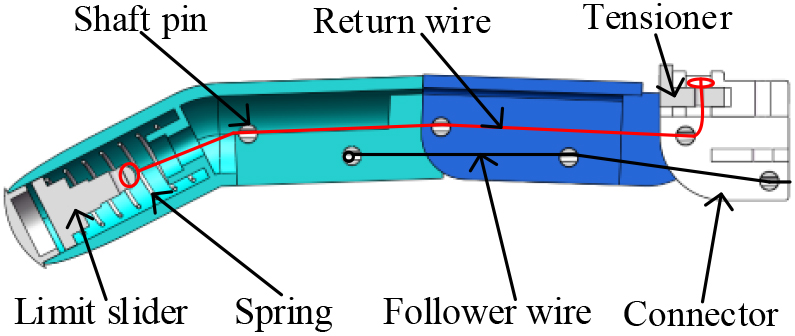
The device generates tension with the increase of finger curvature, and the tensioner is located at the other end to provide an appropriate preload. When the motor rotates, both the driven line and the return line are tensioned, causing the spring to be compressed. Therefore, the tensioned driven line generates torque on the pinhole joint of the MCP and PIP shaft, which makes the joint torque, which is opposite to the torque generated by the return line. Therefore, the tension applied to the return line is proportional to the compression amount of the spring. When the motor loosens the guide wire, the driven wire relaxes, and the compressed spring returns to drive the finger to straighten. The above process completes the bending and straightening of fingers.
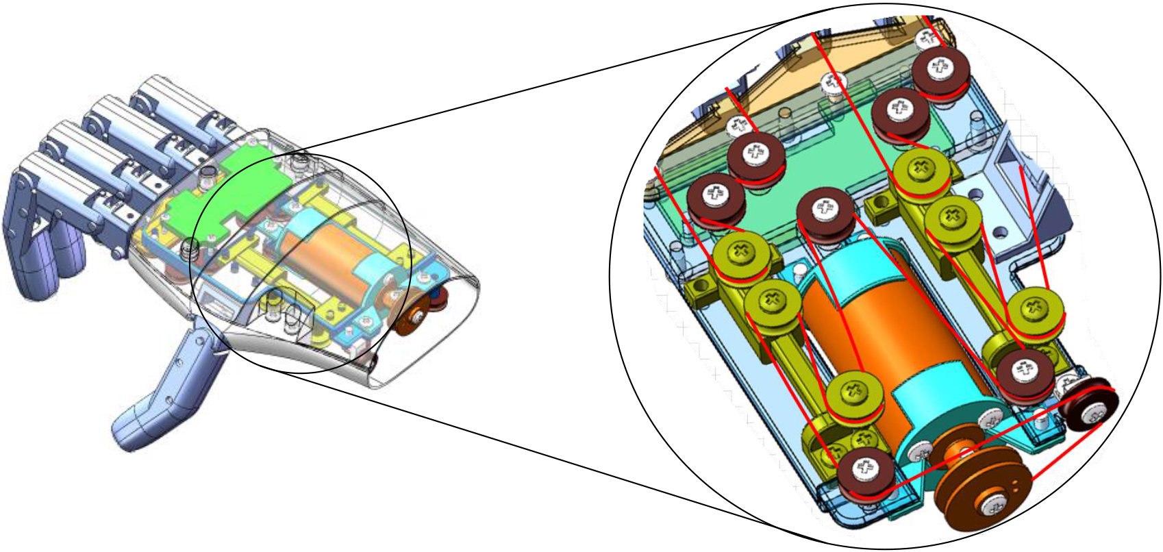
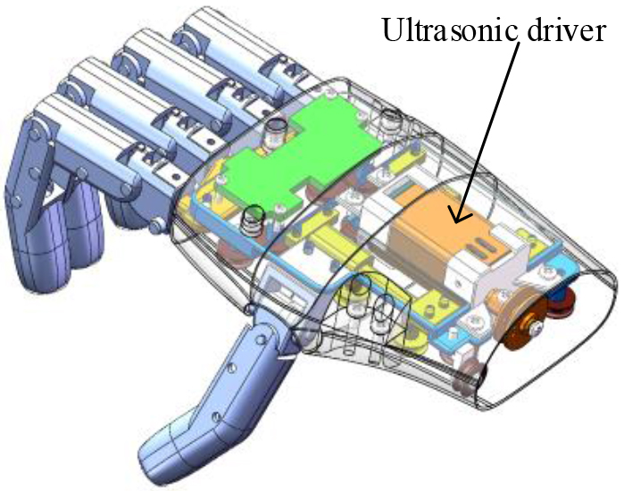
The main parts of the hand, including the electric actuator, the control panel, and the transmission mechanism, are all arranged in the palm, which makes the palm space structure very compact. The power system is composed of a lightweight self-made ultrasonic motor with a high power density and a linear guide rail. The ultrasonic motor drives the wire and transmits the force and speed to the pulley rope-based mechanism in the palm of your hand through the transmission system. The wire starts from the motor, ends at the thumb, and passes through two differential elements installed on the linear guide rail. Each differential element is made of a bearing and a guide rail, and the sleeve moves along the two guide rails. Two pulleys are installed on each shaft sleeve: one pulley supports the guide wire, and the second pulley passes through the driven wire for driving fingers. There are two driven lines: the first driven line is used to drive the index finger and middle finger, while the second driven line is used to drive the ring finger and little finger. To avoid lead slack, the assembly also includes a spring acting on the linear guide rail. Figure 2 is a schematic diagram of the palm.
Figure 2.
Schematic diagram of palm structure.
2.2Ultrasonic motor
In the structural design of the whole prosthetic hand, the fingers and palm parts are manufactured and processed by 3D printing technology, and the pulleys, linear guide rails, and circuit boards selected are all small and light in weight. A motor drives the whole prosthetic hand to ensure the lightweight design of the prosthetic hand. However, due to the limitation of the driving principle, the traditional motor has the characteristics of a large mass, complex structure, slow response, low positioning accuracy, large volume, etc., which does not meet the design requirements of the lightweight prosthetic hand, and the positioning accuracy of motion control is not enough, which greatly affects the overall performance of the lightweight prosthetic hand.
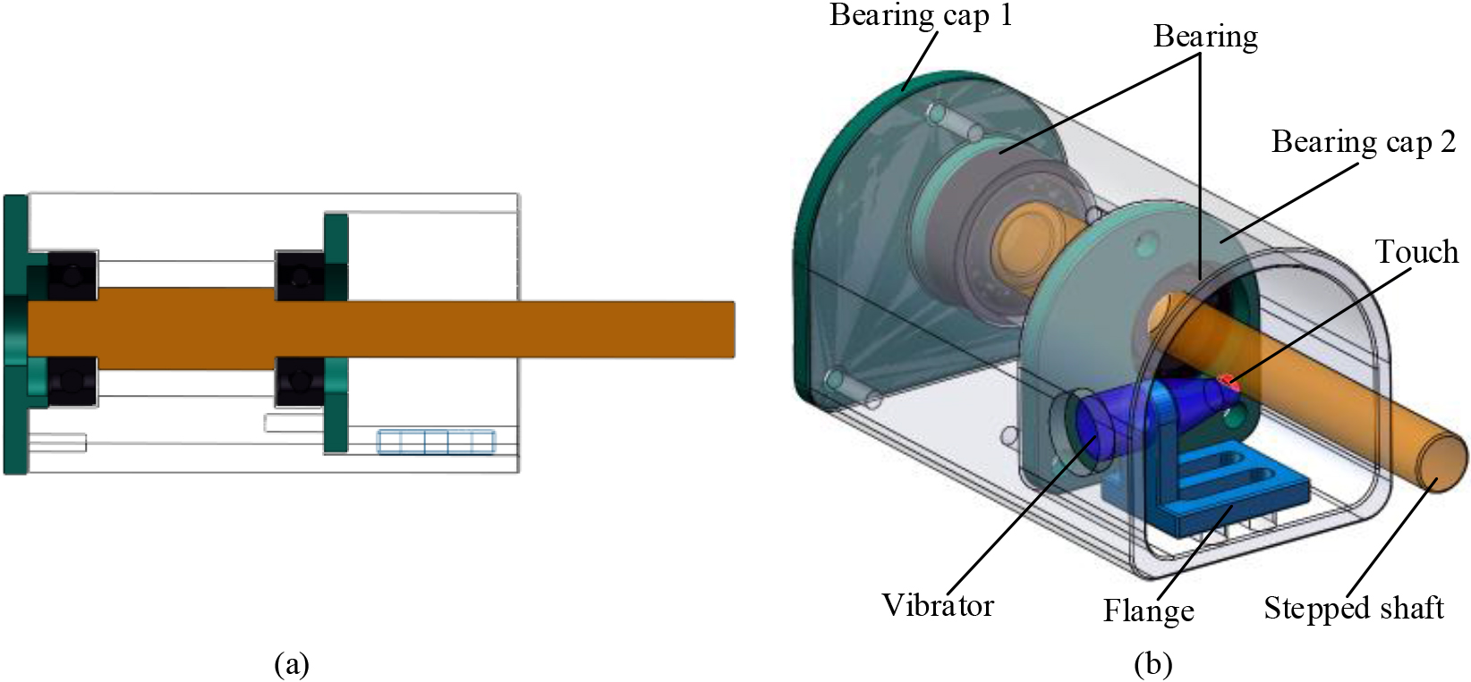
To realize the maximum weight reduction of the prosthesis, an ultrasonic driver is designed to replace the traditional motor, and the lightweight, small volume, simple structure, accurate positioning, high power density, and fast response time of the ultrasonic driver are used to meet the requirements of lightweight design and precise control. Figure 3 is a structural diagram of an ultrasonic driver model. The ultrasonic driver is composed of a stepped shaft, a bearing, a bearing cover, a vibrator, a flange, and a shell. By adjusting the position of the flange, the vibrator and the stepped shaft are brought into pressure contact, and the red part is the contact point on the way. In this case, the piezoelectric ceramic sheet is given to exciting the vibrator’s driving foot at the resonance frequency corresponding to the longitudinal vibration formation, so that the vibrator vibrates longitudinally. Under the action of friction, the driving foot makes the stepped shaft rotate radially, and the ultrasonic driver starts to work. The overall structure is to avoid interference with the guide rail in the palm. The front view of ultrasonic driver is shown in Fig. 3(a), and the axonometric view of ultrasonic driver is shown in Fig. 3(b).
Figure 3.
Structure diagram of the ultrasonic driver model. (a). The front view of ultrasonic driver (b). The axonometric view of ultrasonic driver.
2.3Simulation analysis of ultrasonic vibrator
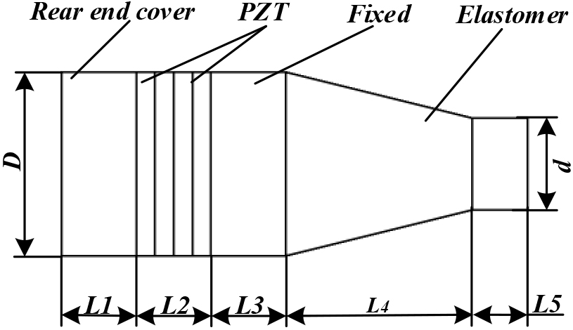
For the designed ultrasonic motor, its vibrator structure size is as shown in Fig. 4, which is composed of an elastic body, a fixed flange, a ceramic plate, and a rear end cover. The size value is;
Figure 4.
Structural dimension diagram of the ultrasonic vibrator.
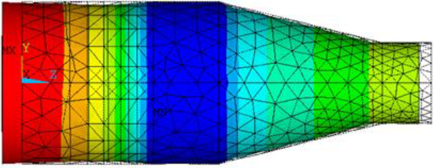
Firstly, the modal response of the vibrator is analyzed, and the constraint conditions during work are imposed. The different modal formations and their corresponding resonance frequencies of the vibrator are obtained, and the required modal formations are searched for dynamic analysis, to guide the application of conditions in actual tests. Here, the longitudinal vibration formation of the vibrator is used. In ANSYS, the command flow method is used to solve its formation, and the frequency range is 20 KHz–200 KHz. It is found that the main formation of the sixth order is longitudinal vibration, and the corresponding frequency is 194243 Hz. The vibration deformation of the vibrator along the longitudinal direction is shown in Fig. 5.
Figure 5.
Vibration longitudinal deformation diagram.
3.Results and discussion
3.1Finger kinematics simulation of a prosthetic hand
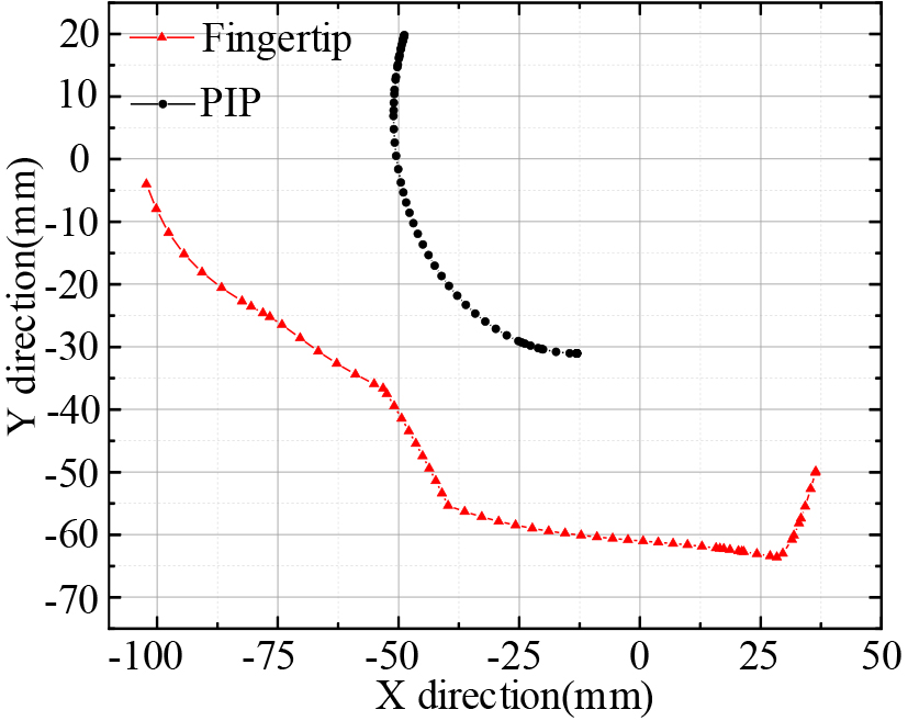
After the structural design, the rationality of the kinematics principle is analyzed, the finger is introduced into the kinematics analysis software, the rope simulation model is established, the contact condition limit is set, and the movement trajectory data of finger PIP and Fingertip are collected by drawing the data derived from the kinematics simulation. The pin hole at the heel of the finger is taken as the origin, and the finger straightening direction is the X-axis; so that the movement trajectory positions of two points corresponding to the finger are obtained as shown in Fig. 6. As can be seen from the figure, the movement trajectory of the index finger PIP and Fingertip is similar to that of finger grasping (without physical grasping). The horizontal movement range of PIP and Fingertip is about 38 mm and 140 mm, and the vertical movement range is about 50 mm and 60 mm, respectively. In the vertical direction, the PIP joint moves upward in a circular track at first, but after reaching the joint contact condition, it moves downward in a circular track under the torque provided by the driven line due to the structural restriction.
Figure 6.
Motion trajectories of PIP and fingertip.
3.2Motion simulation of the ultrasonic actuator
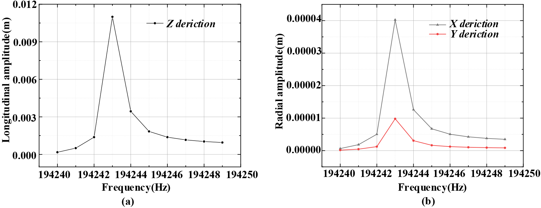
From the results in Section 2.3 and Fig. 5, it can be seen that under the vibration excitation of frequency 194244 Hz, the formation of the vibrator is longitudinal vibration, with the maximum longitudinal amplitude at the lower end of this frequency. Therefore, we selected the excitation frequency of 194243 Hz as the resonant frequency of the ultrasonic oscillator. When the constraint is applied, a sinusoidal ultrasonic voltage of 194244
Figure 7.
Harmonic response diagram of longitudinal vibration of the vibrator.
Transient analysis can obtain real-time status of the actual operation of the ultrasonic oscillator and system. In order to visually express the actual working situation of the ultrasonic vibration system, this article conducts transient analysis on the real-time state of the ultrasonic oscillator. Through simulation analysis, we obtained the motion trajectory of the particle at the end of the ultrasonic oscillator over time. In the simulation study of transient analysis, the frequency of the AC voltage applied to both ends of the piezoelectric ceramic plate in this paper is 194243 Hz, with an effective value of 200 V. Meanwhile, the phase difference of the ultrasonic driving voltage is 90 degrees, and the damping coefficient is 0.003. To obtain the vibration characteristics of the vibrator, the motion path curve of the particle on the surface of the driving foot is extracted after analysis, as shown in Fig. 8.
Figure 8.
Motion path curve of a particle on driving foot surface.
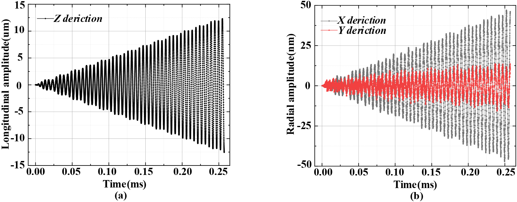
From Fig. 8, it can be seen that in the transient analysis results of the ultrasonic vibration system under sinusoidal voltage excitation, the axial amplitude of the contact point at the end of the ultrasonic oscillator is much greater than the radial amplitude, and the longitudinal amplitude is more obvious. The maximum longitudinal amplitude at the top of the ultrasonic oscillator shown in Fig. 8(a) is 12.5
3.3Experiment of motor and artificial hand
The above ultrasonic driver is applied to the light-weight artificial limb hand, and the further lightweight design of the artificial limb is completed on the premise that other parts are unchanged. To avoid interference and facilitate the processing and assembly of parts, the shell of the ultrasonic driver is designed into a structure of half circle and the other half rectangle, the assembly effect is shown in Fig. 9.
Figure 9.
Prosthetic hand with ultrasonic driver.
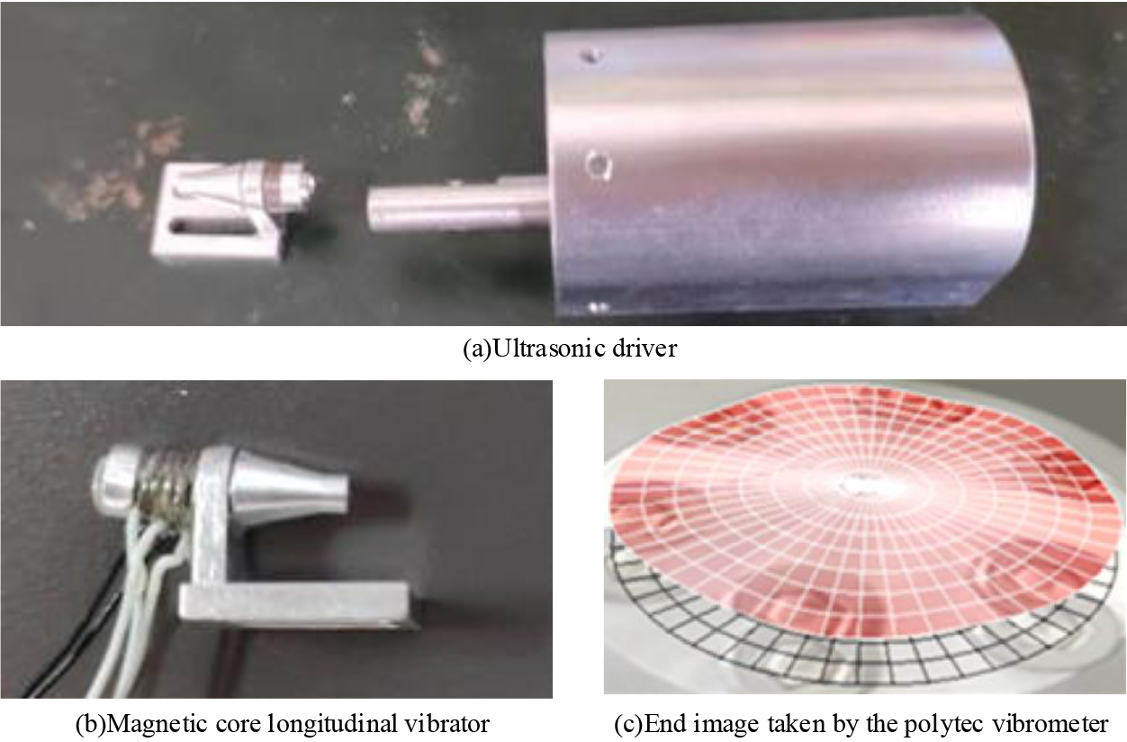
The related physical image of the ultrasonic driver is shown in Fig. 10. Figure 10(a) is a physical view of an ultrasonic motor, Fig. 10(b) is a magnetic core longitudinal vibrator in the motor, and Fig. 10(c) is a model of longitudinal vibration of the vibrator obtained by shooting an ultrasonic transducer with a vibrometer.
Figure 10.
Related physical images of ultrasonic drivers.
3.4Discussion
The prosthetic hand designed in this paper, which is driven by a rope, has a good lightweight, and can drive multiple fingers using a motor linkage. At the same time, a new driving mode is designed to drive the prosthetic hand.
The current research on prosthetic hands mainly includes rigid driving structures and flexible driving structures. The rigid driven structure of the prosthetic hand is mainly driven by an electric motor, while the flexible driven prosthetic hand is mainly driven by ropes or pneumatic. This paper proposes a new rigid driven prosthetic hand, which is driven by an ultrasonic motor.
Compared to traditional research, the research in this manuscript has advantages:
a. Compactness, low cost, and light weight;
b. Ultrasonic motor drive has anti-interference characteristics;
c. Functionally, it has more biomimetic characteristics.
However, compared to previous studies, there are also certain limitations:
a. The prosthetic hand in this article has not yet achieved commercial or large-scale application research.
b. There are significant shortcomings in the anthropomorphism of the appearance of the prosthetic hand in this article.
c. There is relatively little research on intelligent control of prosthetic hands in this article.
We hope that we can continue to study anthropomorphism and intelligent driving in the future, and contribute to the development of prosthetic hands.
4.Conclusion
In this paper, a kind of artificial limb hand driven by rope is designed, and the driving motor using ultrasonic motor is designed and manufactured. First of all, this paper designs a kind of artificial finger driven by rope and spring rebound. The bending performance and motion trajectory of the finger are simulated, which meet the needs of the prosthetic hand. Through the use of complex pulleys, the coupling structure design of one driving rope driving five fingers is realized. Thus, completing the overall design of the prosthetic hand. Then, by designing an ultrasonic transducer and a special driving structure, the core device is designed, and the performance is verified by simulation and experiment. Finally, we processed and tested the designed prosthetic hand.
This article studies the driving structure based on ultrasonic motors. And determine the structural dimensions of the ultrasonic motor vibrator through modal and transient simulation analysis. By replacing traditional actuators with new types of actuators, lightweight design of prosthetic hands can be achieved, improving motion accuracy and optimizing the driving performance of prosthetic hands. The biomimetic hand driven by the ultrasonic motor in this article has the characteristics of biomimetic, compact, low-cost, and lightweight. I hope that the prosthetic hand proposed in this article can be applied as soon as possible, bringing benefits to relevant demand groups.
Acknowledgments
This work was supported by Pilot Projects for Fundamental Research in Suzhou (Grant No. SSD2023014), the Natural Fund of Shandong Province (Grant no. ZR2022QH214), and the Key R&D Plan of Jiangsu Province (Grant no. BE2021012).
Conflict of interest
None to report.
References
[1] | Briko A, Kapravchuk V, Kobelev A, Hammoud A, Leonhardt S, Ngo C, Gulyaev Y, Shchukin S. A Way of Bionic Control Based on EI, EMG, and FMG Signals. Sensors. (2022) ; 22: (1). |
[2] | Castro MCF, Pinheiro WC, Rigolin G. A Hybrid 3D Printed Hand Prosthesis Prototype Based on sEMG and a Fully Embedded Computer Vision System. Frontiers in Neurorobotics. (2022) : 15. |
[3] | Weiner P, Starke J, Rader S, Hundhausen F, Asfour T. Designing Prosthetic Hands With Embodied Intelligence: The KIT Prosthetic Hands. Frontiers in neurorobotics. (2022) ; 16: : 815716-815716. |
[4] | Segil JL, Pulver B, Huddle S, Weir RFF, Sliker L. The Point Digit II: Mechanical Design and Testing of a Ratcheting Prosthetic Finger. Military Medicine. (2021) ; 186: : 674-680. |
[5] | Yang H, Wei G, Ren L, Qian Z, Wang K, Xiu H, Liang W. An Affordable Linkage-and-Tendon Hybrid-Driven Anthropomorphic Robotic Hand-MCR-Hand II. Journal of Mechanisms and Robotics-Transactions of the Asme. (2021) ; 13: (2). |
[6] | Lu H, Zou Z, Wu X, Shi C, Liu Y, Xiao J. Biomimetic Prosthetic Hand Enabled by Liquid Crystal Elastomer Tendons. Micromachines (Basel). (2021) ; 12: (7): 736. |
[7] | Dunai L, Novak M, Garcia Espert C. Human Hand Anatomy-Based Prosthetic Hand. Sensors. (2021) ; 21: (1). |
[8] | Abd MA, Ingicco J, Hutchinson DT, Tognoli E, Engeberg ED. Multichannel haptic feedback unlocks prosthetic hand dexterity. Sci Rep. (2022) ; 12: (1): 2323. |
[9] | Capsi-Morales P, Piazza C, Catalano MG, Grioli G, Schiavon L, Fiaschi E, Bicchi A. Comparison between rigid and soft poly-articulated prosthetic hands in non-expert myo-electric users shows advantages of soft robotics. Sci Rep. (2021) ; 11: (1): 23952. |
[10] | Kashef SR, Amini S, Akbarzadeh A. Robotic hand: A review on linkage-driven finger mechanisms of prosthetic hands and evaluation of the performance criteria. Mechanism and Machine Theory. (2020) : 145. |
[11] | Kim U, Jung D, Jeong H, Park J, Jung HM, Cheong J, Choi HR, Do H, Park C. Integrated linkage-driven dexterous anthropomorphic robotic hand. Nat Commun. (2021) ; 12: (1): 7177. |
[12] | Gao G, Shahmohammadi M, Gerez L, Kontoudis G, Liarokapis M. On Differential Mechanisms for Underactuated, Lightweight, Adaptive Prosthetic Hands. Front Neurorobot. (2021) ; 15: : 702031. |
[13] | Estay D, Basoalto A, Ardila J, Cerda M, Barraza R. Development and Implementation of an Anthropomorphic Underactuated Prosthesis with Adaptive Grip. Machines. (2021) ; 9: (10). |
[14] | Deng E, Tadesse Y. A Soft 3D-Printed Robotic Hand Actuated by Coiled SMA. Actuators. (2021) ; 10: (1). |
[15] | Jeong SH, Kim K-S, Kim S. Designing Anthropomorphic Robot Hand With Active Dual-Mode Twisted String Actuation Mechanism and Tiny Tension Sensors. IEEE Robotics and Automation Letters. (2017) ; 2: (3): 1571-1578. |
[16] | Zhao H, O’Brien K, Li S, Shepherd RF. Optoelectronically innervated soft prosthetic hand via stretchable optical waveguides. Science robotics. (2016) ; 1: (1): eaai7529. |
[17] | Lee DH, Park JH, Park SW, Baeg MH, Bae JH. KITECH-Hand: A Highly Dexterous and Modularized Robotic Hand. IEEE/ASME Transactions on Mechatronics. (2017) ; 22: (2): 876-887. |
[18] | Wahit MAA, Ahmad SA, Marhaban MH, Wada C, Izhar LI. 3D Printed Robot Hand Structure Using Four-Bar Linkage Mechanism for Prosthetic Application. Sensors. (2020) ; 20: (15). |
[19] | Wang Y, Tian Y, She H, Jiang Y, Yokoi H, Liu Y. Design of an Effective Prosthetic Hand System for Adaptive Grasping with the Control of Myoelectric Pattern Recognition Approach. Micromachines. (2022) ; 13: (2). |
[20] | Ryu W, Choi Y, Choi YJ, Lee YG, Lee S. Development of an Anthropomorphic Prosthetic Hand with Underactuated Mechanism. Applied Sciences. (2020) ; 10: (12). |
[21] | Choi KY, Akhtar A, Bretl T. A Compliant Four-bar Linkage Mechanism that Makes the Fingers of a Prosthetic Hand More Impact Resistant. IEEE Int Conf Robot Autom. (2017) : 6694-6699. |
[22] | Cuellar JS, Plettenburg D, Zadpoor AA, Breedveld P, Smit G. Design of a 3D-printed hand prosthesis featuring articulated bio-inspired fingers. Proc Inst Mech Eng H. (2021) ; 235: (3): 336-345. |
[23] | Chen T, Zhao X, Ma G, Tao B, Yin Z. Design of 3D-printed Cable Driven Humanoid Hand Based on Bidirectional Elastomeric Passive Transmission. Chinese Journal of Mechanical Engineering. (2021) ; 34: (1). |
[24] | Controzzi M, Clemente F, Barone D, Ghionzoli A, Cipriani C. The SSSA-MyHand: A Dexterous Lightweight Myoelectric Hand Prosthesis. IEEE Transactions on Neural Systems and Rehabilitation Engineering. (2017) ; 25: (5): 459-468. |
[25] | Laffranchi M, Boccardo N, Traverso S, Lombardi L, Canepa M, Lince A, Semprini M, Saglia JA, Naceri A, Sacchetti R, Gruppioni E, Michieli LD. The Hannes hand prosthesis replicates the key biological properties of the human hand. Science Robotics. (2020) ; 5: (46): eabb0467. |
[26] | Fajardo J, Ferman V, Cardona D, Maldonado G, Lemus A, Rohmer E. Galileo Hand: An Anthropomorphic and Affordable Upper-Limb Prosthesis. IEEE Access. (2020) ; 8: : 81365-81377. |
[27] | Kumar DK, Jelfs B, Sui X, Arjunan SP. Prosthetic hand control: A multidisciplinary review to identify strengths, shortcomings, and the future. Biomedical Signal Processing and Control. (2019) : 53. |
[28] | Taylor F, Au C. Forced Air Cooling of Shape-Memory Alloy Actuators for a Prosthetic Hand. Journal of Computing and Information Science in Engineering. (2016) ; 16: (4). |
[29] | Krausz NE, Rorrer RA, Weir RF. Design and Fabrication of a Six Degree-of-Freedom Open Source Hand. IEEE Trans Neural Syst Rehabil Eng. (2016) ; 24: (5): 562-72. |
[30] | Hocaoglu E, Patoglu V. Design, Implementation, and Evaluation of a Variable Stiffness Transradial Hand Prosthesis. Frontiers in neurorobotics. (2022) ; 16: : 789210-789210. |
[31] | Ryndzionek R, Sienkiewicz L. A review of recent advances in the single- and multi-degree-of-freedom ultrasonic piezoelectric motors. Ultrasonics. (2021) ; 116: : 106471. |
[32] | Yin Z, Dai C, Cao Z, Li W, Chen Z, Li C. Modal analysis and moving performance of a single-mode linear ultrasonic motor. Ultrasonics. (2020) ; 108: : 106216. |
[33] | Xu D, Zhang X, Zhao L, Yu S. A Novel Rotary Ultrasonic Motor Using the Longitudinal Vibration Mode. IEEE Access. (2019) ; 7: : 135650-135655. |


