
A structural analysis of the rail unit of an indoor assistive mobility system
Abstract
BACKGROUND:
Individuals with gait disturbances, such as that post-stroke, are discharged home to undergo outpatient rehabilitation. Rehabilitation in the community is not as effective as that in hospital, due to long travel times and short program duration.
OBJECTIVE:
This study analyzed rail unit structure, with the aim of assisting home indoor assistive mobility system (HIAMS) development, allowing patients to undergo gait-related rehabilitation training at home.
METHODS:
The HIAMS consists of a mobile rail running around the whole room, a turn-table for movement between rails, and a weight-supporting component. Structural analysis was performed using the Abaqus/CAE solution (Version 6.14, Dassault systems, Inc.) to verify device safety, according to the load applied to the rail and turn-table units. The load was applied vertically at 150 kg to reflect the weight of potential users.
RESULTS:
Structural analysis was performed on the weight-supporting components, which was consist of turn-table case, bearing components (center, left), connective bracket and rail rollers. The safety factors of each components were estimated as 1.31, 5.39 (bearing, center), 8.45 (bearing, left), 1.43 and 3.61 in sequence.
CONCLUSION:
We demonstrated a safety factor of
1.Introduction
South Korea was deemed an aged society in 2017, and by the second half of 2024 it will become a super-aged society, with older adults accounting for
These symptoms reduce independence and restrict the patients’ activities of daily living (ADL) post-stroke. Around 66% of stroke patients exhibit some ongoing physical dysfunction, impacting their ADL in approximately 75% of cases [5]. Limited access to their physical environment and reduced independence not only affects patients’ psychological and social wellbeing, but reduces their quality of life, and impedes their human rights [6]. Hence, the ability to carry out ADL impacts the prognosis of post-stroke patients, and is regarded as a predictor of functional recovery [7].
Scheduled rehabilitation training programs using assistive devices are routinely used to treat gait impairments. Gait rehabilitation devices are categorized into five types; treadmill-based, foot-plate-based, over-ground, exoskeleton-assisted and active short-leg brace types [8]. The most researched and commercialized products are treadmill-based assistive devices, with a harness attachment to suspend the patient whilst providing support [9]. Hesse et al. investigated partial body weight support (BWS) and the effect of treadmill gait training in hemiplegic patients [10, 11]. Werner compared the training effects of a conventional gait training device with a weight-supporting treadmill device in subacute stroke patients [12]. However, the device was criticized for requiring two therapists [13], and for limiting natural patient movement due to fixed user positioning.
This study aimed to develop an over-ground gait training device to assist with gait training and to improve patient ADLs. To prevent falls, a ceiling-rail was included; the rail was installed on the ceiling and a suspension unit added to assist with safety during stance and gait training. Despite limited studies assessing ceiling-rails, various studies have compared the kinematic and kinetic parameters between treadmills and over-ground gait training methods [14, 15, 16, 17], and weight-supported treadmills with over-ground methods in patients with stroke or incomplete spinal cord injuries [18, 19, 20, 21, 22]. Lee et al. conducted a clinical study on 36 patients with hemiplegia to verify the effects of over-ground gait training using a ceiling-rail device. After the 8-week intervention, the gait training was shown to have improved the ankle range of motion, static balance and walking speed in hemiplegic patients [23].
The findings indicated that the use of gait assistive devices with ceiling-rails would allow effective gait training in daily life, as well as improve independence in daily activities. However, ceiling-rail gait assistive devices have so far only been developed to allow movement in fixed directions, and require a relatively large installation space [23, 24, 25, 26]. Due to limited utility in daily life, these devices have previously mostly been installed in hospitals only. As a result, the rehabilitation of hemiplegic patients usually begins in hospital, then requires outpatient attendance to a rehabilitation unit. The ability to travel limits patient access to rehabilitation, while the relatively short time of rehabilitation training limits therapeutic effects and reduces patient motivation. Therefore, it is necessary to develop a home-based indoor assistive mobility system to allow the gait rehabilitation training. We developed a ceiling-rail rehabilitation system for home application, including a mobile rail to allow mobilization around the entire room, a turn-table to allow movement between rails, and a weight-support unit to assist with gait. A structural analysis was subsequently performed.
2.System configuration
2.1Overview
As shown in Fig. 1, the home indoor assistive mobility system (HIAMS) developed in this study was designed for to assist patients with ADL performed at home. The device consists of a rail unit installed at each indoor space, a turn table to assist with movement across rooms and a weight-support unit. The rail unit has two sections of fixed rail in each room, and a mobile rail installed between the two fixed rails to enable mobilization around the entire room. The turn-table unit assists with movement from one room to another. The weight-support unit supports the user whilst they carry out their ADL, including sitting, standing and walking in accordance with their current ability level.
Figure 1.
Visualized concept of the home indoor assistive mobility system.
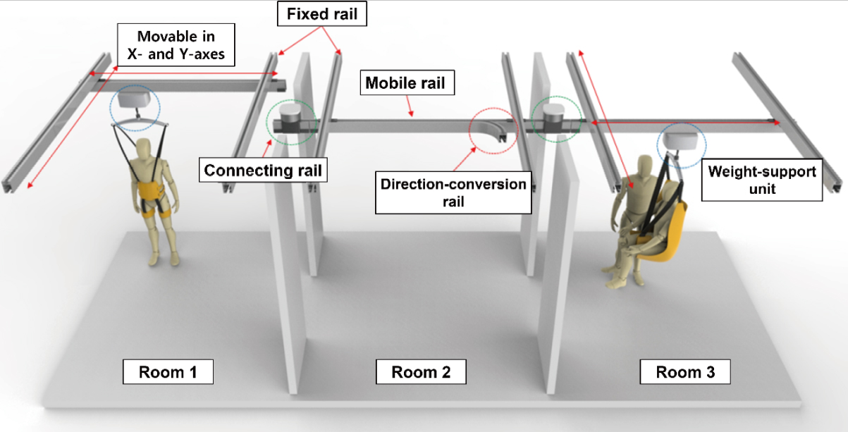
2.2Assistance with indoor movements
Once home, the individual with gait impairment performs their ADLs in an indoor environment. These movements can be divided into vertical movements, like sitting and standing, and horizontal movements such as walking. During these movements, the device should be able to withstand the weight-support unit customized to the user’s weight and level of gait impairment.
The design of the rail unit installed in each room and the turn-table are shown in Fig. 2. The rail unit is divided into two fixed rails and two room-covering mobile rails to allow the entire space of the room, along the X and Y axes, to be covered. The fixed rail is attached at the two ends of the ceiling along a single axis as shown in Fig. 2. One of the mobile rails is connected to the two fixed rails, allowing movement along the other axis.
Figure 2.
Design of the room-covering rails and turn-table unit.
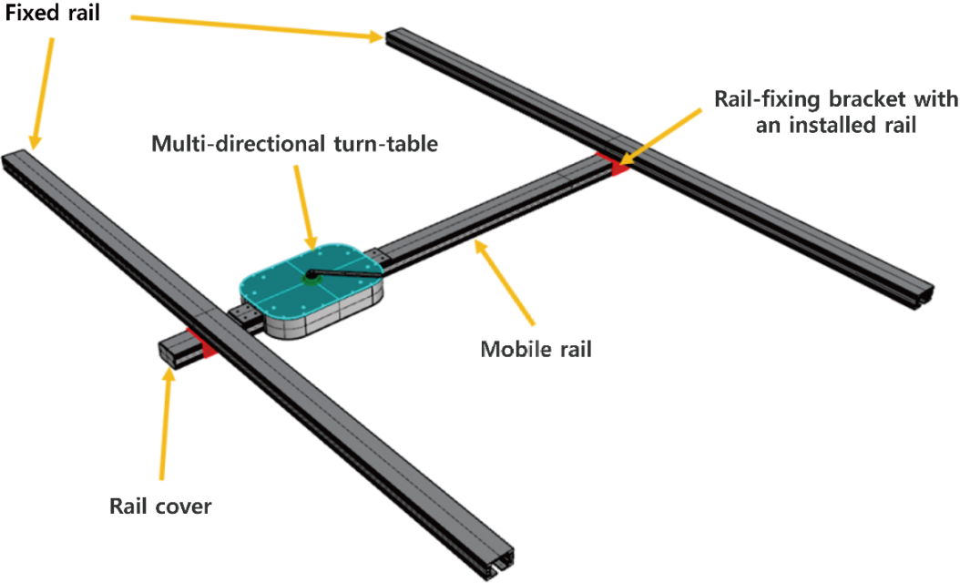
The turn-table used to change direction, as shown in Fig. 2, is installed at one end of the mobile rail in each room. Movement from one room to another requires combination of the direction-conversion rail from the turn-table with the mobile rail from the other room.
Figure 3.
Design of the turn-table unit.
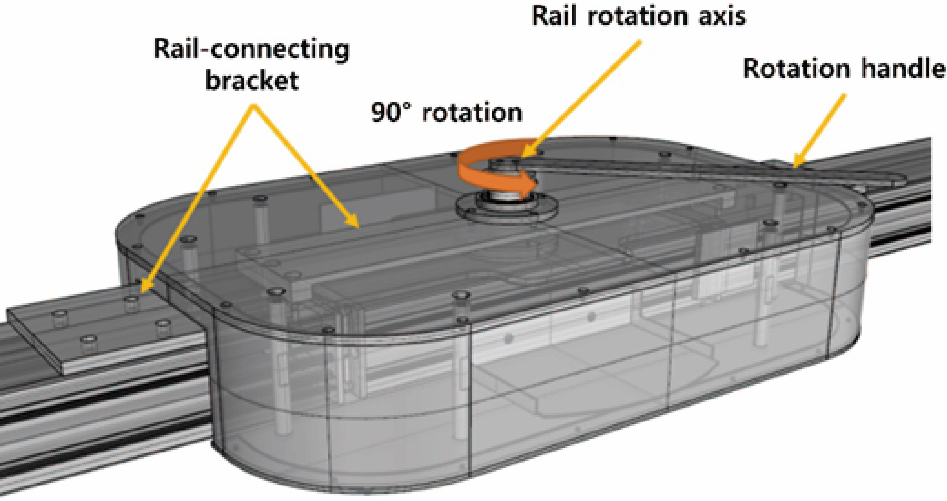
Figure 4.
Design of detailed turn-table unit.
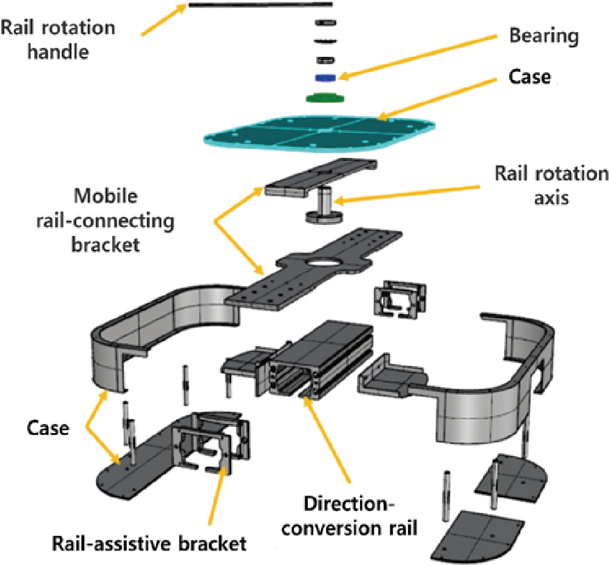
Figure 5.
Simplified model of rail and turn-table parts orientation during structural analysis.
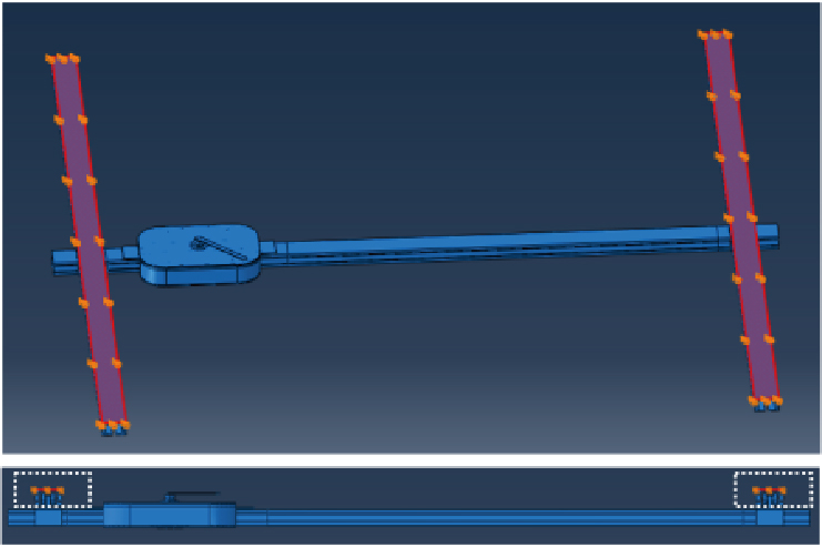
Figure 6.
Structural analysis of ceiling-rail and turn-table parts including maximum 150 kg load.
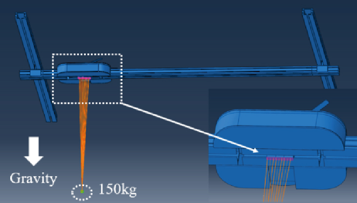
Figure 3 details the turn-table design, including how it facilitates movement between rooms. The turn-table comprises a passive rotational conversion part, allowing movement to other rooms with a direction-conversion rail, and the detailed dimensions of the module are 496.0 mm wide, 380.0 mm long, and 99.2 mm high, and its weight is 26 kg. It also includes a part that integrates with the mobile rail, and a case. To change direction towards the target room, the user should turn the rotation handle to align the direction-conversion rail with the rail installed in the other room.
Figure 4 shows how each component is assembled within the turn-table. The turn-table is connected to the mobile rail with a bracket. A bearing and a rail rotational axis were added to for a smooth connection between the rail rotation handle and the direction-conversion rail.
3.Structural analysis: Methods
To verify the structural safety of the rail and turn-table units according to the vertical load of the user, the Abaqus/CAE solution (Version 6.14, Dassault systems Incs.) was used.
The HIAMS developed in this study targets individual with gait impairment, who returns home after intensive care at the hospital. These individuals are able mobilize independently with an assistive tool, such as a cane or walker, and require support with 50% of their body weight or less. One-hundred-and-fifty kilograms was selected as the weight to test structural safety, as it is twice the average weight of adult males, giving a two-fold safety load.
To test the structural safety of the ceiling-rail and the turn-table, the mobile rail was fixed on the upper part of the fixed rail (Fig. 5), and the maximum load of 150 kg was applied to the lower part of the mobile rail module (Fig. 6).
Table 1 presents the material properties of the mobility system components. The turn-table case was aluminum (AL6061-T5, AL6063-T6), the bearing in connection with the rotation grip was stainless steel (SUS304, SUS440C), the bracket connected with the mobile rail was stainless steel (S45C) and the material of the roller was silicon rubber.
Table 1
Material properties of the ceiling-rail and turn-table parts
| Material properties | AL6061 -T6 | S45C | SUS304 | SUS440C | Silicone rubber |
|---|---|---|---|---|---|
| Density (kg/m | 2,700 | 7,850 | 8,000 | 7,800 | 2,250 |
| Young’s modulus (MPa) | 68,900 | 205,000 | 193,000 | 204,000 | 950 |
| Poisson’s ratio | 0.33 | 0.29 | 0.29 | 0.28 | 0.45 |
| Yield strength (MPa) | 276 | 343 | 215 | 450 | 72.5 |
| Tensile strength (MPa) | 310 | 569 | 505 | 760 | 82.6 |
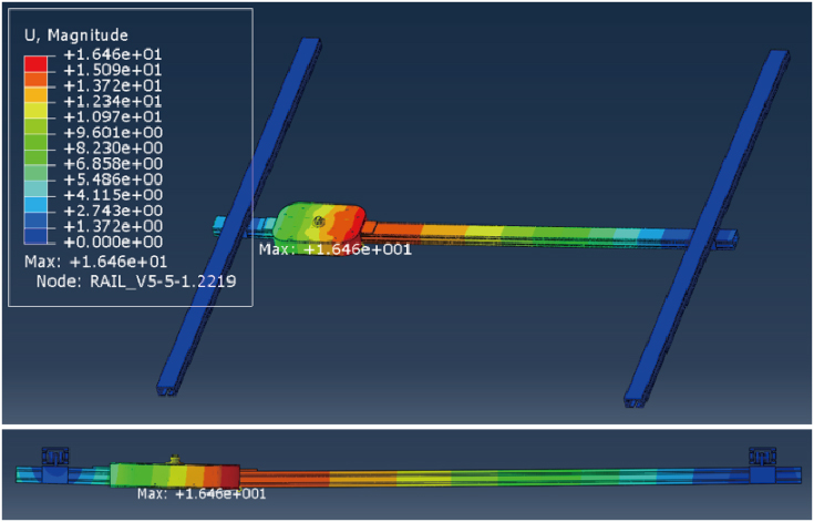
Figure 7.
Structural analysis of stress on rail and turn-table components using a 150 kg-load.
4.Structural analysis: Results
Immediately after hospital discharge, patients may need an assistive device to help regain mobility. It is important that the assistance is directed toward the vertical load in consideration of the user’s weight. In this study, a simulation program was used to verify the structural safety of the rail and turn-table units of the HIAMS, focusing on vertical load.
Figure 7 presents the representative result of structural analyses on the fixed and mobile rails, using a 150 kg-load on the lower part of the turn-table. The colors in the top left corner indicate the load forces on each rail using a 150 kg load. The color spectrum from green to blue indicates a reducing load and from green to red indicates an increasing load.
Figure 8.
Structural analysis of stress on turn table case using a 150 kg-load.
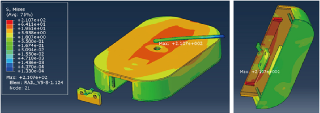
Figure 9.
Structural analysis of stress on the bearing component using a 150 kg-load.
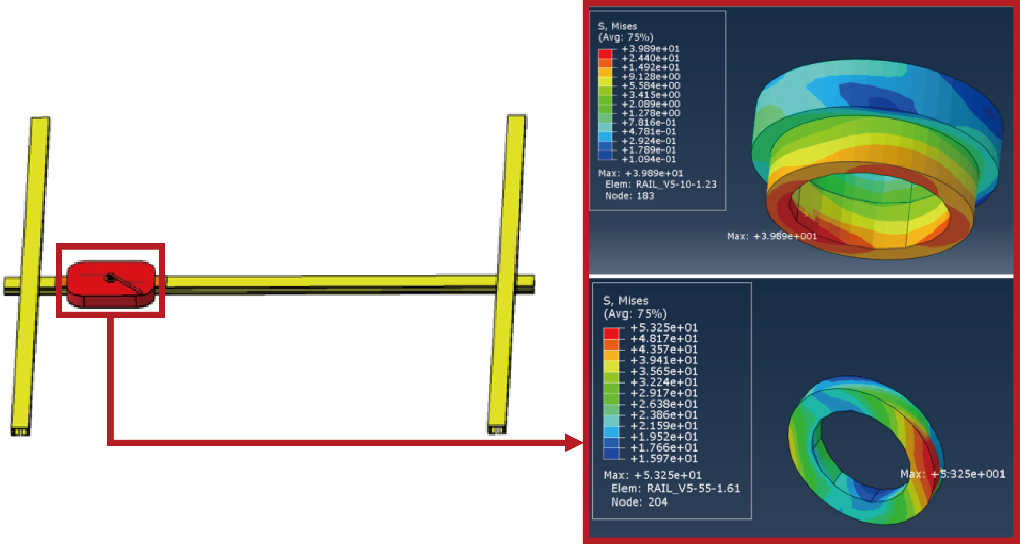
Figure 10.
Structural analysis of stress on the connective bracket using a 150 kg-load.
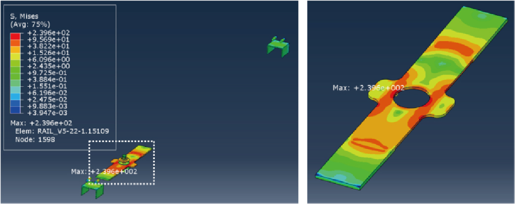
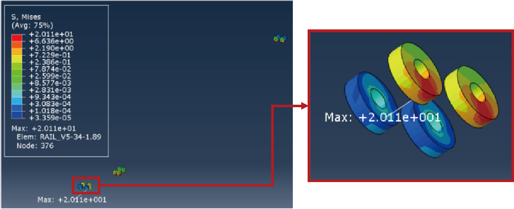
Figure 11.
Structural analysis of stress on rail rollers using a 150 kg-load.
Figures 8–11 present the results of the structural analyses on the weight-supporting components. Figure 8 shows the stress on the turn-table case structure, revealing an overall spectrum of yellow and light red. As in Fig. 6, the central area received the most stress, with a maximum of 210.7 MPa. As the yield strength of the case material aluminum (AL6061-T6) is 276 MPa, the safety factor was estimated as 1.31. Hence, the component maintains a safety factor
Figure 9 presents the bearing component results as the passive rotation handle of the turn-table is applied to change direction. The center of the bearing, again, had the highest load, with maximum stress of 39.89 MPa on the left bearing and 53.25 MPa on the right. The materials of both bearing were different types of stainless steel (SUS304 and SUS440C), with yield strengths of 215 MPa and 450 MPa, yielding safety factors of 5.39 and 8.45 accordingly. This confirmed the structural safety for the entire unit of bearing, including the central area receiving the highest load.
Figure 10 presents the results of the bracket component that connects the turn-table to the mobile rail. The maximum stress on the bracket was 239.6 MPa. As the yield strength of the bracket material (S45C) is 215 MPa, the safety factor was estimated as 1.43, indicating that the bracket received a similarly high load to that of the turn-table case.
Figure 11 shows the simulation result for the roller that allows turn-table mobility. As the roller was designed using a silicon rubber material for smooth movements, the load on the roller was shown to be relatively low. The max stress was 20.11 MPa, and as the material yield strength of silicon rubber is 72.5 MPa, the safety factor was estimated as 3.61, confirming its structural safety with a 150 kg load.
5.Conclusions
This study was conducted to develop a home-based rail system to assist with the rehabilitation training of patients after hospital discharge post-stroke. A structural analysis was performed on the rail unit of the system. Considering that the maximum load of the expected user of this product is 90 kg, the stress on the mobile rail and the turn-table was analyzed with a 150 kg load applied in the direction of gravity. The maximum stress was found on the bracket that connects the turn-table case to the mobile rail, while the rail roller bearing experienced minimal stress. As the maximum stress on each component was below their relative material yield strength, structural safety was confirmed. These results are expected to be reflected in structurally safe design methods when manufacturing rail systems for households in the future. A limitation of this study is that it did not consider dangerous situations such as actual users’ falls. In a sudden situation such as a fall, it may take more than 1.5 times of one’s own body weight. To this end, future research plans to verify structural safety even with a load of 250 kg or more. Based on the design in this study, for which the structural safety has been verified, a prototype will be fabricated, and an indoor mobility test will be conducted in a follow-up study.
Author contributions
Conception and design of study: Je Nam Kim, Kyong Kim, Chang Ho Yu.
Acquisition of funding: Je Nam Kim, Kyong Kim; Acquisition of data: Je Nam Kim, Yu Sung Seo; Analysis and/or interpretation of data: Je Nam Kim, Kyong Kim, Chang Ho Yu; Drafting the manuscript: Je Nam Kim, Mi Yeon Shin, Kyong Kim; Revising the manuscript critically for important intellectual content: Mi Yeon Shin, Yu Sung Seo, Chang Ho Yu; Approval of the final version to be published: Kyong Kim, Chang Ho Yu.
Ethical compliance
Research experiments conducted in this article with animals or humans were approved by the Ethical Committee and responsible authorities of our research organization following all guidelines, regulations, legal, and ethical standards as required for humans or animals.
Acknowledgments
This work was supported by the Korea Medical Device Development Fund grant funded by the Korean government (Ministry of Science and ICT, Ministry of Trade, Industry and Energy, Ministry of Health & Welfare, and Ministry of Food and Drug Safety) (Project Number: KMDF_PR_20200901_0199) and supported by the Basic Science Research Program through the National Foundation of Korea (NRF) funded by the Ministry of Education (No. NRF-2020R1C1008728).
Conflict of interest
The authors have no conflicts of interest to declare.
References
[1] | Statistics Korea, Population Projections for Korea: 2020 |
[2] | Ministry of Health and Welfare, National Emergency Medical Center, National Medical Center. Statistics of Emergency Medical; (2021) . |
[3] | Kelley RE, Borazani AP. Stroke rehabilitation. Neurological Research. (2009) ; 31: (8): 832-840. |
[4] | Ryerson S, Levit K. Functional Movement Reeducation: A Contemporary Model for Stroke Rehabilitation, New York; Churchill Livingstone, 1st edition; (1997) : 433-440. |
[5] | Sturm JW, Dewey HM, Donnan GA, Macdonell RAL, McNeil JJ, Thrift AG. Handicap after stroke: How does it relate to disability, perception of recovery, and stroke subtype? The north North East Melbourne Stroke Incidence Study (NEMESIS). (2002) ; 33: (3): 762-768. |
[6] | Lee KJ, Choi YY. The Latest of Social Welfare for People with Disabilities. Hakjisa; (2018) . |
[7] | Kwakkel G, Wagenaar RC, Kollen BJ, Lankhorst GJ. Predicting disability in stroke: A critical review of the literature. Age and Ageing. (1996) ; 25: (6): 479-489. |
[8] | Diaz JJG, Sanchez E. Lower-limb robotic rehabilitation: Literature review and challenges. Journal of Robotics. (2011) ; 2011: : 1-11. |
[9] | Kim TS. Identifying perceived usability factors of a pre-gait rehabilitative robot design. Journal of Product Research. (2019) ; 37: (3): 25-32. |
[10] | Hesse S, Bertellt C, Schaffrin A, Malezic M, Mauritz KH. Restoration of gait in nonambulatory hemiparetic patients by treadmill training with partial body-weight support. Arch. Phys. Med. Rehabil. (1994) ; 75: : 1087-1093. |
[11] | Hesse S, Bertelt C, Jahnke MT, Schaffrin A, Baake P, Malezic M, Mauritz KH. Treadmill training with partial body weight support compared with phyiotherapy in nonambulatory hemiparetic patients. Stroke. (1995) ; 26: : 976-981. |
[12] | Werner C, Frankenberg SV, Treig T, Konrad M, Hesse S. Treadmill training with partial body weight support and an electromechanical gait trainer for restoration of gait in subacute stroke patients a randomized crossover study. Stroke. (2002) ; 33: : 2895-2901. |
[13] | Kosak MC, Reding MJ. Comparison of partial body weight-supported treadmill gait training versus aggressive bracing assisted walking post stroke. Neurorehabil Neural Repair. (2000) ; 14: : 13-19. |
[14] | Alton F, Baldey L, Caplan S, Morrissey MC. A kinematic comparison of overground and treadmill walking. Clinical Biomechanics. (1998) ; 13: (6): 434-440. |
[15] | Riley PO, Paolini G, Croce UD, Paylo KW, Kerrigan DC. A kinematic and kinetic comparison of overground and treadmill walking in healthy subjects. Gait & Posture. (2007) ; 26: : 17-24. |
[16] | Lee SJ, Hidler J. Biomechanics of overground vs. treadmill walking in healthy individuals. J. Appl. Physiol. (2008) ; 104: : 747-755. |
[17] | Kang YE. Effect of treadmill gait training on the dynamic balance ability and walking pattern of chronic stroke patients. M.S. thesis, Department of Sports Rehabilitation, Korea national Sport University, Seoul, Korea; (2022) . |
[18] | Hesse S, Konrad M, Uhlenbrock D. Treadmill walking with partial body weight support versus floor walking in hemiparetic subjects. Arch. Phys. Med. Rehabil. (1999) ; 80: (4): 421-427. |
[19] | Dobkin B, Apple D, Barbeau H, Basso M, Behrman A, Degorge D, Ditunno J, Dudley G, Elashoff R, Fugate L, Harkema S, Saulino M, Scott M. Weight-supported treadmill vs over-ground training for walking after acute incomplete SCI. Neurology. (2006) ; 66: (4): 484-493. |
[20] | Miller EW, Quinn ME, Seddon PG. Body weight support treadmill and overground ambulation training for two patients with chronic disability secondary to stroke. Phys. Ther. (2002) ; 82: : 53-61. |
[21] | Kim SC, Hur YG. The effect of treadmill and body weight support treadmill training on balance and gait ability in hemiplegia, patients. Journal of Korean Physical Therapy Science. (2018) ; 25: (1): 31-43. |
[22] | Chae SY. Effects of Downhill Treadmill Gait Training on Balance and Gait in Stroke Patients. M.S. thesis, Department of Physical Therapy, Honam University, Gwangju, Korea; (2019) . |
[23] | Lee SJ, Kim DH, Sim YJ. Effects of 8 weeks suspension-rail gait training on ankle ROM, gait speed and balance in patients with hemiplegia stroke. Exercise Science. (2017) ; 26: (2): 115-121. |
[24] | Kim K, Song WK, Chong WS, Yu CH. Structural analysis of a rehabilitative training system based on a ceiling rail for safety of hemiplegia patients. Technology and Health Care. (2018) ; 26: (2018): S259-S268. |
[25] | Kim K, Chong WS, Yu CH. Rehabilitative training system based on a ceiling rail for detecting the intended movement direction of a user. Technology and Health Care. (2020) ; 28: (2020): S443-S452. |
[26] | Kim JN, Shin MY, Chong WS, Yu CH, Kim K. Development of rail-based dynamic rehabilitation training system considering user’s movement. Journal of Mechanics in Medicine and Biology. (2022) ; 22: (2022): 2240003. |


