
Simulation study on assist-as-needed control of a rehabilitation robotic walker
Abstract
BACKGROUND:
Along with China entering an aging society, the percentage of people that over 60 will reach 34.9% in 2050, resulted in a significant increase in stroke patients.
OBJECTIVE:
This paper proposes a rehabilitation robotic walker for walking assistance during the daily life, and a control method for the motor relearning during the gait training. The walker consists of an omni-directional mobile platform (OMP) which ensures the walker can move on the ground, a body weight support system (BWS) which is capable of providing the desired unloading force, and a pelvic assist mechanism (PAM) to provide the user with four degrees of freedom and avoid the rigid impact. The study goal is to gain a better understanding of the assist-as-needed control strategy during the gait training.
METHODS:
For the man-machine interaction control, the assist-as-needed control strategy is adopted to guide the users’ motions and improve the interaction experience. To build the force field in the three-dimensional space, the dynamics of the system is derived to increase the accuracy of force control.
RESULTS:
The simulation results show that the force field around the motion trajectory was generated in the three-dimensional space. In order to understand the force field, we designed the simulation on sagittal plane and the controller can generate the appropriate force field. The preliminary experiment results were consistent with the simulation results.
CONCLUSION:
Based on the mathematical simulation and the preliminary test, the results demonstrate that the proposed system can provide the guide force around the target trajectory, the accuracy of force control still remains to be improved.
1.Introduction
With many countries entering the aging society, more than 100 million stroke patients were declared, and a total number of 12.2 million were reported in 2019, according to the report data of the Global Burden of Disease (GBD) [1]. The strokes are a major cause of death and extremity disability in world, and elderly care need to occupy a significant portion of the medical care resources [2, 3, 4]. For the disability of the lower extremity limits functional independence in activities of daily living, the research of lower extremity robotic walker, which is more effective than traditional gait training in improving waking ability and balance, receives extensive attentions [5, 6]. During gait rehab, the pelvic movement plays an important role, as the center of gravity (CoG) is located close to the pelvic center, but the walking-associated pelvic movements are not being performed appropriately in the elderly, therefore, the motion trajectory of the CoG significantly contributes to the gait balance and metabolic cost [7]. Furthermore, the pelvic obliquity and lateral motion of pelvis have a play in the smooth weight shift between the two legs [8, 9]. However, the research about the motion guidance of the pelvis needs to be further studied.
In the literature focused on pelvic motions, previous researches showed that most stroke survivors suffer from the balance disorder and abnormal pelvic movements [10]. To solve the problem caused by pathological pelvis motions, robotic interventions and new control strategies have been studied. Vashista et. al. designed a Tethered Pelvic Assist Device (TPAD) to teach users to walk with the target pelvic trajectory while walking in the Columbia University, and a force field control method is adopted to guide the pelvis to move on a target trajectory [11]. To train patients walk on a treadmill, Aoyagi et al. designed a Pelvic Assist Manipulator (PAM) in the University of California, and a position-based control method is adopted to move the pelvis along a predefined path [12]. In order to encourage the stroke survivors for their active involvement, Olenšek et al. proposed a balance assessment robot (BAR) that has three passive degrees of freedom (DoF) and three actuated DoF to control the pelvis, and an admittance-controlled system is developed, in such a way that the natural movement of pelvis is not significantly affected [13]. Besides, the KineAssist robot [14], the Robot assisted gait training (RAGT) [15], the assist robotic walker (JARoW-II) [16], the NaTUre-gaits robot [17] and the AssistOn-Gait system [18] are developed to study the pelvic control.
The main contribution is that: 1) the assist-as-needed control strategy is mainly used in the upper limbs rehab and rope driving device, the servo drive with springs needs to be further studied; 2) based on the dynamics and compliant mechanism, the assist-as-needed controller is designed to guide the pelvic motions; 3) the force field is generated by conjunction of the servo drive and the compliant mechanism.
To pave the way for the clinical application of the assist-as-needed control strategy, we designed a robotic walker for those stroke patients, and the description of the robotic walker and the control flow were detailed in this paper. Besides, the mathematical simulation is underpinned by the dynamic modeling of the walker. For verification of the proposed method, preliminary test with a health volunteer were presented. Compared with the results of the previous studies, this paper proposed a new method to intervene the pelvic movements, however, the precision of the control error still be improved.
2.Method
2.1Robotic walker design
On the basis of previous studies [19], the novel robotic walker is designed to implement the pelvic trajectory control. Generally, a robotic walker consists of three parts: the OMP, the BWS and the PAM, as shown in the Fig. 1. The body weight support system works in conjunction with a mobile platform to achieve gait training, and the pelvic assist mechanism is adopted to smooth the pelvic motions. As shown in Fig. 1, we designed a walker that consists of three main parts: i) an omni-directional mobile platform; ii) a body weight support system and iii) a pelvic assist mechanism. Compared with the previous walker, the linear motor module is adopted to replace the four-bar mechanism to provide the offloading force, and the pelvic assist mechanism that has four passive degrees of freedom is adopted to replace the pelvic brace.
Figure 1.
Conceptualized design of the robotic walker. The OMP represents the omni-directional mobile platform, BWS represents the body weight support system and PAM represents the pelvic assist mechanism. The BoS is the boundary of support.
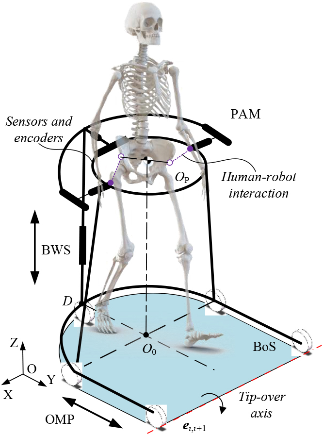
Figure 2.
The CAD model of the system.
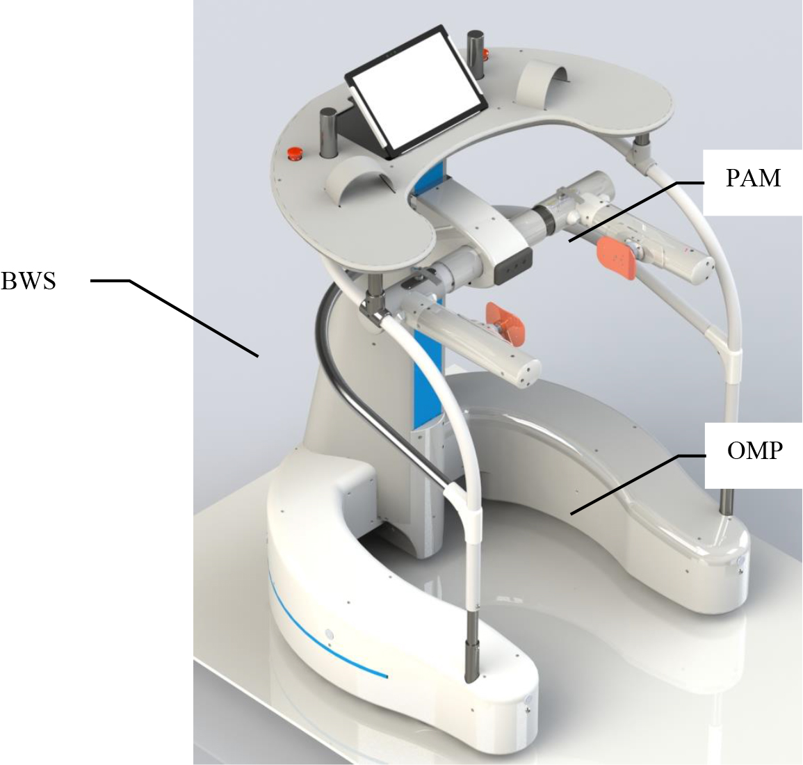
Based on the demand analysis of the stroke survivors and the clinical trial results, the conceptualized design of the robotic walker is carried out. The overall conceptualized design of the walker is shown in Fig. 1, the walker provides the user with body support and mobility assistance via the BWS and the OMP respectively. Besides, the PAM plays an important role in the motion trajectory of the CoG. After that, the CAD model of the system is designed, as shown in Fig. 2. The OMP is designed to provide over-ground mobility assistance, and guide the motion trajectory of the CoG in the transverse section. The OMP consists of three active omnidirectional wheels to achieve the mobility assistance, two passive castors to maintain the balance of the whole walker. Above the five wheels, a U-shaped steel structure is designed to install the electronic components, such as the battery pack, Programmable Logic Controller (PLC), and relays. According to the motion analysis and the gate width, the U-shaped structure is designed to satisfy approximately 0.6 m of free space in the lateral direction, 0.9 m of free space in the forward direction. The BWS is fixed on the U-shaped structure.
The BWS is mainly composed of a rectangular tube and a linear motor module, which is drived by a servo motor to realize the approximately 0.6 m of vertical displacement of the pelvis. The PAM is installed on the sliding block of the linear motor module. Between the PAM and the BWS, a torque sensor is installed to measure the interaction force between the walker and human in the vertical direction. After that, a spline shaft and a spline hub are installed to achieve the lateral motion of the pelvis, and a tension-compression sensor is installed to monitor the lateral motion of the pelvis. On both side of the pelvis, two linear motion modules are installed to achieve the forward motion of the pelvis, with the help of two spherical hinges on the spline hub, the pelvic obliquity and pelvic rotation can be realized.
In addition, the bearing surface is fixed on the top of the BWS, which is used to bind the forearms of the patient. On the bearing surface, two control levers are installed to help the user to manipulate the walker on the ground, and a display screen is adopted to show the information for patients.
2.2Problem statement
During bipedal walking on the ground, the interchange between kinetic and potential energies is a continuous process, and the motion trajectory of the CoG plays an important role in this process. The traditional rehabilitation robot and control strategy usually fix the pelvis and neglect the pelvic motions. To change the status of rehab training, the assist-as-needed control strategy is adopted to guide the motion trajectory of the CoG during the gait. As shown in Fig. 3, the walker controls the three wheels to generate a force field around the target path, when the center of the pelvis deviates the target path, the controller can calculate the normal force via the distance from the point C to the point Q to guide the user, then the patient can learn from the CoG control.
Figure 3.
Schematic diagram of the walker.
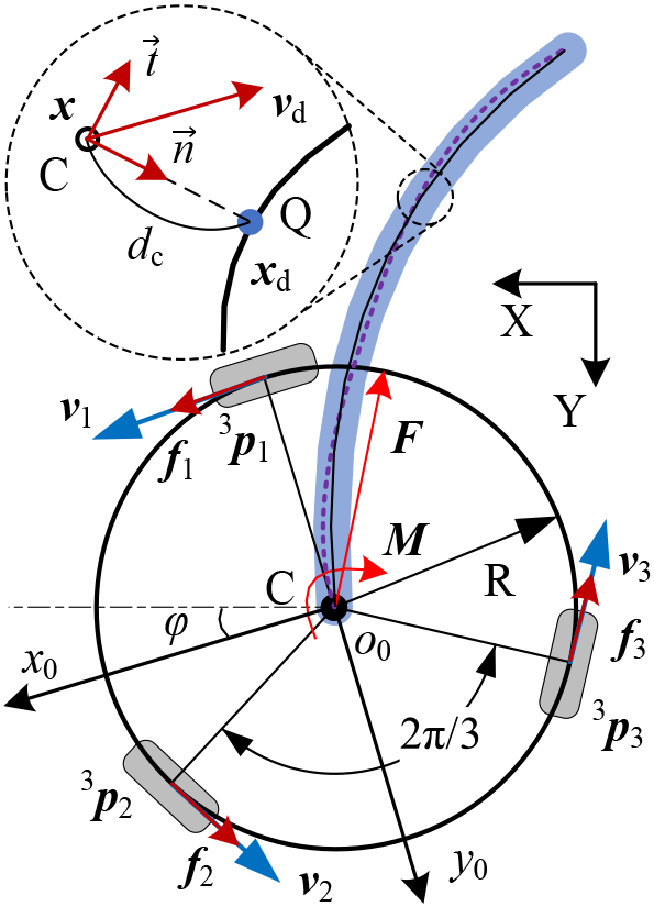
Figure 4.
Force field generated by the BWS and the OMP. The HSV color scale encodes the force field in the workspace, and the unit of the scale is Newton (N).
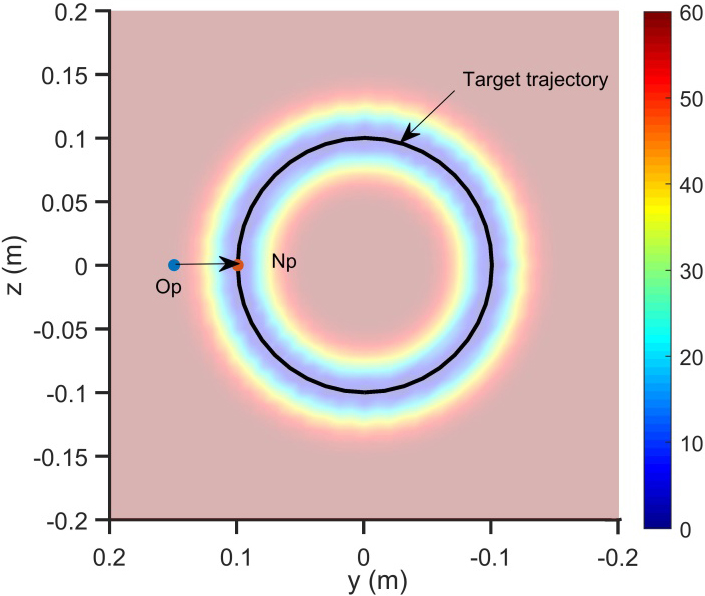
In a similar way, the walker can assist the user to control their CoG in the sagittal plane, as shown in Fig. 4 the BWS is responsible for the force in the vertical direction and the OMP is responsible for the force in the forward direction. When the CoG deviates the target path, the PLC searches the nearest point Np at the target path, then controls the four servo motors to generate appropriate force on the pelvis, the interactive sensors can help to feedback the force control. Affected by the composition error and zero drift of the interactive sensors, and irrelevant motions and instability of the CoG, the motion control of the walker is challengeable. Therefore, the Kalman filtering (KF) was enforced to relieve the aforementioned interference.
2.3Dynamic model
To generate the appropriate force field, speed control of the servo motor can’t fulfill the requirement of the force control, thus the torque control is adopted to improve the accuracy. In this chapter, the kinetic equation of the walker is derived to build the mapping relation between the human machine interaction force/torque and the motor output, so the controller can implement the guide force via the control of the motor output.
Define the mapping relation in the motion space of the robotic walker as:
(1)
where
(2)
(3)
where the
(4)
where the
(5)
Take the structure parameter into the mathematical model to calculate the Jacobian matrix, for the active part of the walker, the Jacobian matrix
(6)
Then the
(7)
For the passive part of the walker, the flexibility of the PAM can be calculated by the stiffness matrix [20], then we can obtain the wrench
(8)
where
For the active part of the walker, the backward recursive method is adopted to calculate the joint wrench [21], the wrench acting on the
(9)
Project the wrench into the joint axis by
(10)
where
(11)
(12)
(13)
where
Then explicit expression of the torque of the BWS can be obtained:
(14)
2.4Torque control
The controller is designed to assist patients with walking and provide the force field around the target path, as shown in Fig. 5. During the operation of the walker, the controller generates the reference trajectory (RT:
Figure 5.
Force field control architecture of the robotic walker.
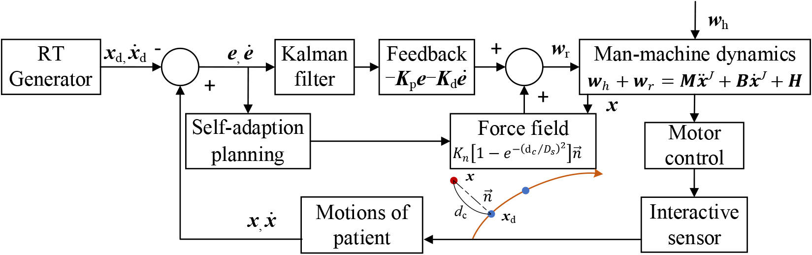
The calculation formula of the normal force is as follows:
(15)
where
3.Computer simulation and results
To verify the usability of the proposed control method, simulation studies and preliminary test with health volunteer were carried out in this paper. In the simulation, the MATLAB was employed to simulate the generation processes of the force field with the various RT. Preliminary experiment was performed with a healthy volunteer.
The simulation results are shown in Figs 6 and 7, Fig. 6 shows the force field in the three-dimensional space, and the RT is the motion trajectory of the CoG in a gait cycle. In the process of simulation, the force at the z-axis was generated by the component in the Eq. (15), which was generated by motor output of the BWS, and the force on the transverse section was generated by the component in the Eq. (15), which was generated by motor output of the OMP. With different phases of rehabilitation and biological parameters of the patients, the RT and the intensity of the force field is designed. The black full line represents the RT, and the guide force in the three-dimensional space is displayed by the HSV color. As shown in Fig. 6, when the pelvis moves along the RT, the normal force near zero. And with the deviation increase, the normal force increase, and the direction of the force point to the RT.
Figure 6.
Force field in the three-dimensional space and the RT in a gait cycle. The HSV color scale encodes the force field in the workspace, and the unit of the scale is Newton (N).
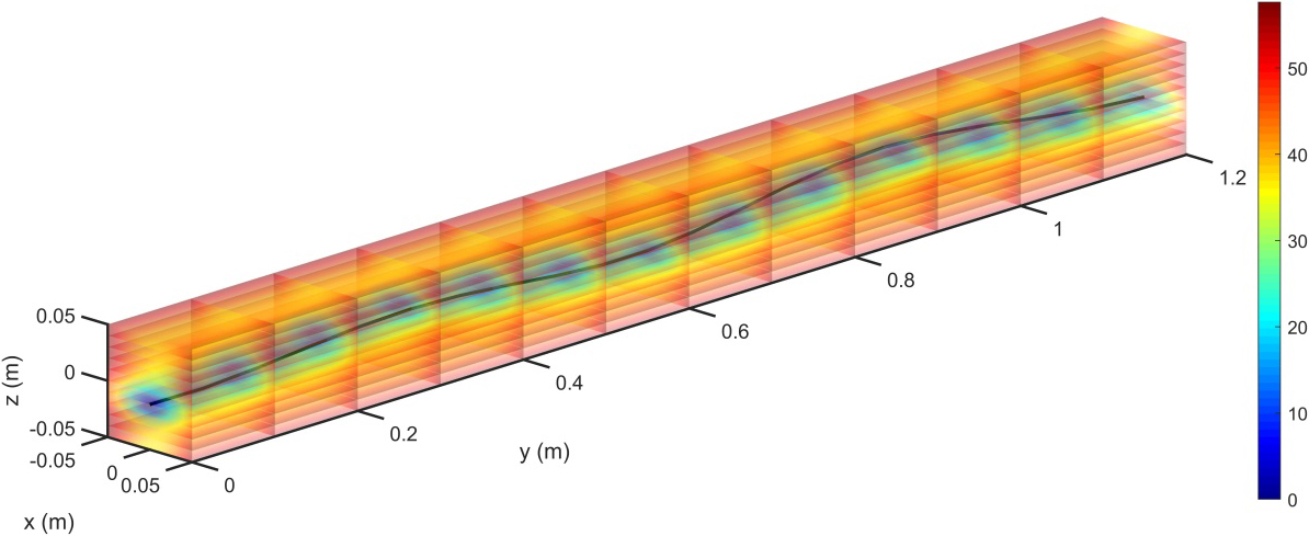
Figure 7.
Force field on sagittal plane and the force direction. The HSV color scale encodes the force field in the workspace, and the unit of the scale is Newton (N).
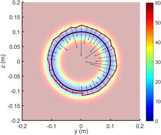
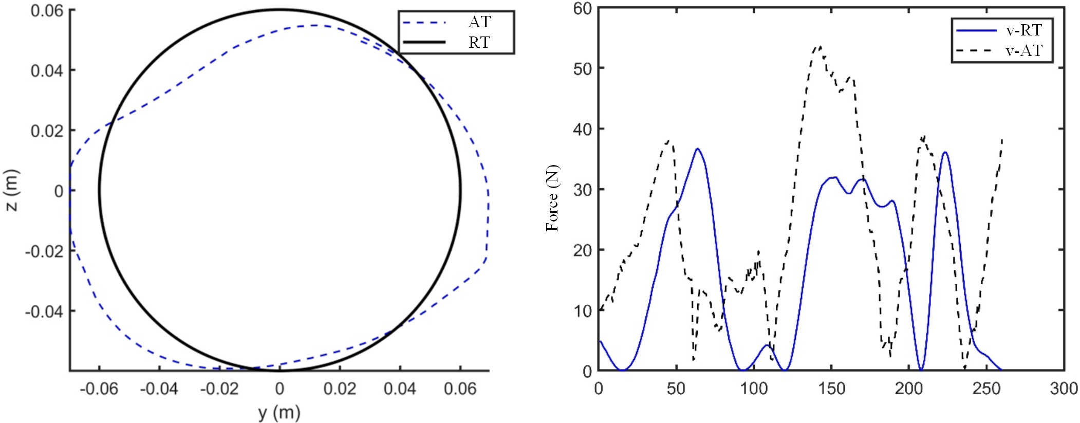
Figure 8.
Test results of the force field control. v-RT is the theoretical value and v-AT is actual value.
Except for the RT of walking, during the training of joint motion of the lower limbs, the training on the sagittal plane is helpful. As shown in Fig. 7, the force field on sagittal plane can be generated by the BWS and the OMP, the actual path is generated by the random function in the MATLAB, the black line with an arrow represents the size and orientation of the normal force. The simulation results demonstrate that the controller can generate the appropriate force field, and the force can help the patient to correct the motion trajectory of the CoG.
To verify the effectiveness of the proposed control method, the control of the force field on the sagittal plane was carried out with a healthy volunteer. The healthy volunteer was asked to control the walker by his pelvis, and finish the circular RT, the pelvis affected by the force field. The actual trajectory (AT) was obtained by the encoder of the motors, and the normal force was calculated by the interaction sensors. The test results were shown in the Fig. 8, the black line was the RT, and the blue dotted-line was the actual trajectory (AT), the healthy volunteer finished the RT, and the AT was near the RT. When the AT deviated from the RT, the normal force was increased with hysteresis, as shown in the Fig. 8b. The test results demonstrate that the volunteer can fulfil the task with certain errors, however, the error of interaction force was affected by the signal delay of the sensors. Compared with the experimental results in [11], the errors between the applied forces and desired forces share similar characteristics, the applied forces were fallen behind the desired forces. In the [22], the asymptotic magnitude of the tracking error was given, and we will discuss the tracking error via the formula.
4.Conclusion
The present work demonstrates that the robotic walker might be a potentially training system with the assist-as-needed control strategy, however, the simulation study only proved the feasibility of the method. The walker can provide the desired unloading force and walking assistance with the help of the BWS and the OMP, and the effectiveness of the walker need further examining. The proposed control algorithm for gait training is proved to be effective in the path track by the MATLAB simulation and preliminary test. In the preliminary test with a healthy volunteer, the test results show that the walker can effectively provide user appropriate force field, the error of interaction force was affected by the signal delay of the sensors. However, the accuracy of force control remains to be improved. The future work is to improve the interaction forces and address torque control.
Acknowledgments
This research was supported by the National Natural Science Foundation of China (Grant U1913206), the Key Project of Science and Technology of Guangdong Education Department (Grant 2020ZDZX2070) the Special Project in Key Fields of Guangdong Universities in High-end Equipment Manufacturing (Grant 2022ZDZX3093), and the Guangdong Basic and Applied Basic Research Foundation (Grant 2019A1515110304).
Conflict of interest
None to report.
References
[1] | Kisa A, Kisa S, Collaborators GS. Global, regional, and national burden of stroke and its risk factors, 1990–2019: a systematic analysis for the global burden of disease study 2019. The Lancet Neurology. (2021) ; 26. |
[2] | Batchelor F, Hill K, Mackintosh S, Said C. What works in falls prevention after stroke? Stroke. (2010) ; 41: (8): 1715-1722. |
[3] | Arnold M, Roe E, Williams D. A pictorial overview of technology-assisted care options for bariatric patients: One hospital’s experience. Ostomy/wound Management. (2014) ; 60: (1): 36-42. |
[4] | Dovgiy I, Svyrydova N. Rehabilitation of patients suffering from ischemic stroke by methods of ozonotherapy, kinesitherapy, physiotherapy and acupuncture. East European Journal of Neurology. (2016) ; 6: (12): 4-9. |
[5] | Martins M, Santos C, et al. A review of the functionalities of smart walkers. Medical Engineering and Physics. (2015) ; 37: (10): 917-928. |
[6] | Neto AF, Gallego JA, Rocon E, et al. Extraction of user’s navigation commands from upper body force interaction in walker assisted gait. BioMedical Engineering OnLine. (2010) ; 9: (1): 1-16. |
[7] | Lee G, Ohnuma T, Chong NY, Lee SG. Walking intent based movement control for JAIST active robotic walker. IEEE Trans Syst Man Cybern Syst. (2014) ; 44: (5): 665-672. |
[8] | Bennett BC, Abel MF, Wolovick A, Franklin T, Allaire PE, Kerrigan DC. Center of mass movement and energy transfer during walking in children with cerebral palsy. Arch. Phys. Med. Rehabil. (2005) ; 86: (11): 2189-2194. |
[9] | Russell SD, Bennett BC, Kerrigan DC, Abel MF. Determinants of gait as applied to children with cerebral palsy. Gait & Posture. (2007) ; 26: (2): 295-300. |
[10] | Roentgen UR, Gelderblom GJ, Soede M, De Witte LP. Inventory of electronic mobility aids for persons with visual impairments: A literature review. Journal of Visual Impairment and Blindness. (2008) ; 102: (11): 702-723. |
[11] | Kang J, Vashista V, Agrawal SK. On the Adaptation of Pelvic Motion by Applying 3-dimensional Guidance Forces Using TPAD. IEEE Trans Neural Syst Rehabil Eng. (2017) ; 25: (9): 1558-1567. |
[12] | Aoyagi D, Ichinose WE, Harkema SJ, Reinkensmeyer DJ, Bobrow JE. A robot and control algorithm that can synchronously assist in naturalistic motion during body-weight-supported gait training following neurologic injury. IEEE Trans. Neural Syst. Rehabil. Eng. (2007) ; 15: (3): 387-400. |
[13] | Olenšek A, Zadravec M, Matjačić Z. A novel robot for imposing perturbations during overground walking: mechanism, control and normative stepping responses. Journal of Neuroengineering & Rehabilitation. (2016) ; 13: (1): 55. |
[14] | Naidu A, Brown D, Roth E. A challenge-based approach to body weight-supported treadmill training poststroke: Protocol for a randomized controlled trial. JMIR Research Protocols. (2018) ; 7: (5): e118. |
[15] | Banala SK, Kim SH, Agrawal SK, Scholz JP. Robot assisted gait training with active leg exoskeleton (ALEX). IEEE Trans Neural Syst Rehabil Eng. (2009) ; 17: (1): 2-8. |
[16] | Ohnuma T, Lee G, Chong NY. Development of JARoW-II active robotic walker reflecting pelvic movements while walking. Intel Serv Robotics. (2017) ; 10: : 95-107. |
[17] | Luu TP, Low KH, Qu X, Lim HB, Hoon KH. Hardware Development and Locomotion Control Strategy for an Over-Ground Gait Trainer: NaTUre-Gaits. IEEE J Transl Eng Health Med. (2014) ; 2: : 2100209. |
[18] | Munawar H, Yalcin M, Patoglu V. Redundant kinematics and workspace centering control of Assist-On-Gait overground gait and balance traine. In: IEEE International Conference on Robotics and Automation. IEEE, (2016) . pp. 3704-3710. |
[19] | Ji J, Chen W, Wang W, Xi J. Design and control of an omni-directional robotic walker based on human-machine interaction. IEEE Access. (2021) ; 9: : 111358-111367. |
[20] | Song Z, Chen W, Wang W, Zhang G. Dynamic modeling and simulation of a body weight support system. J Healthc Eng. (2020) ; 2020: : 2802574. |
[21] | Ji J, Guo S, Xi J, Zhang L. Design and analysis of a smart rehabilitation walker with passive pelvic mechanism. ASME. J. Mechanisms Robotics. (2020) ; 12: (3): 031007. |
[22] | Squeri V, Masia L, Casadio M, Morasso P, Vergaro E. Force-field compensation in a manual tracking task. PLoS One. (2010) ; 5: (6): e11189. |


