
Study on injection molding analysis of glasses-type wearable device for facial skin care
Abstract
BACKGROUND:
With the improvement in the standard of living, there has been increasing interest in facial skin care. In particular, it has been observed that people pay extra attention to eye-skin when they visit skin care parlors for special treatment and care.
OBJECTIVE:
There is a need for skin care devices that would enable convenient skin care anywhere, including at home and on the move. In this research, we developed a prototype of a glasses-type skin care device with a LED (Light-Emitting Diode) irradiation function and performed injection molding analysis of the skin care device model for mass production.
METHODS:
First, the product was designed using a universal design to improve the wearability of the glasses-type skin care device. The first prototype of the skin care device was produced using an integrated LED optical module capable of irradiating at three LED wavelengths to investigate the structural function of the product. The prototype was classified into three mechanisms and injection molding analysis was performed. The fill time, temperature at flow front, injection pressure, clamp force, and deflection values were analyzed according to the appropriate number and location of gates into which the PC
RESULTS:
We found that all the other parts except the temple section of the device were inferior in moldability.
CONCLUSION:
In further studies, the 3D prototype will be modified to enhance moldability, and injection molding analysis with other materials as well as with PC
1.Introduction
As our society progresses, and income levels and the standard of living improve, the desire for physical health and attractive appearance has increased and the interest in skin care has been growing too [1]. As the existing skin care market has grown, with a focus on functional cosmetics in terms of products and beauty parlors and cosmetic surgery services in terms of services, the expenses as well as time required to be spared have grown, limiting the consumers’ choices [2]. However, following the recent phase of social and economic development, the demand for skin care products and services has shown a continuously increasing and diversifying trend, and the demand for home skin care products has increased along with the increase in single households [3]. Currently, various home skin care products are being developed. However, among them, low-level light therapy (LLLT) using the low-power LED (Light-Emitting Diode) is thought to be a method that can be used without the risk of injury or scars. This method is also suitable for the development of devices for use by non-professional individuals [4]. At present, various photo-stimulated skin care devices are available in the market. The photo-stimulated skin care device market records a high growth rate every year. According to a survey, it has been growing at an average annual rate of approximately 10.2% since 2010, and this trend is expected to continue in the foreseeable future [5].
Various studies have been conducted on skin care using LEDs. It has been found that the photons of the LED light source are absorbed by the chromophores or photoreceptors in the skin tissues. This promotes the activity of the mitochondria, which supply energy to the cells, thereby facilitating the metabolic activity of the cells. This can have a significant impact on cell regeneration and restoration [6, 7]. Suck [8]studied the effects of LED irradiation on skin aging in hairless mice and observed similar changes in the epidermis and dermis in response to UV (Ultraviolet) light. Weiss [9] found that collagen composition in the LED-irradiated region was enhanced, wrinkles were reduced, and skin textures improved visibly in a study conducted using a 590-nm LED device [9]. Studies using 630-nm and 830-nm LEDs have shown that LED treatment led to the reduction of wrinkles around the eyes and skin pigmentation and improved skin texture [10, 11, 12]. Kim confirmed that irradiation by 830-nm and 850-nm LEDs reduced melanin production and tyrosinase expression in normal human melanin cells [13]. Furthermore, some studies have reported that UV-induced damage was prevented when human fibroblasts were irradiated with near-infrared light [14, 15].
As a result, various LED skin care devices have been developed. However, most previously released skin care devices have the drawback of being bulky and heavy and, thus, difficult to use for daily life activities such as reading, studying, and housework. Therefore, there is a need for a technology to implement a universal design that will cater to the various sizes of users’ faces and create a home skin care device capable of irradiating at three LED wavelengths instead of at a single wavelength.
In this research, we developed a prototype of a glasses-type skin care device with the LED irradiation function and performed injection molding analysis using the design for mass production. For this purpose, we implemented the three-dimensional design of an eye-skin care device and analyzed its moldability using Moldflow, a three-dimensional injection molding analysis program. A study was conducted to derive the optimal design by comparing the moldability according to the optimum number and location of gates into which the PC
2.Design of eye-skin care device
2.1Universal design of glasses-type eye-skin care device
In addition to inconvenience of use while doing daily life activities such as reading, studying, and housework due to their weight and poor portability, the wearable skin care devices available so far have the disadvantage that handheld products are less user-friendly and make it difficult to do anything else while holding the device. To overcome these limitations, we developed a skin care device with a universal design, employing face data to maximize the versatility, wearability, and user convenience [16]. The average eye size of Koreans analyzed through Size Korea (a Korean national project representing the “Korean Human Body Dimension Survey”) is 3 cm in width and 1.5 cm in length, the length from the middle of the forehead is 3.4–3.6 mm in general, the facial angle is 3
Figure 1.
Mechanical 3D design, prototype, and LED wavelength performance test.
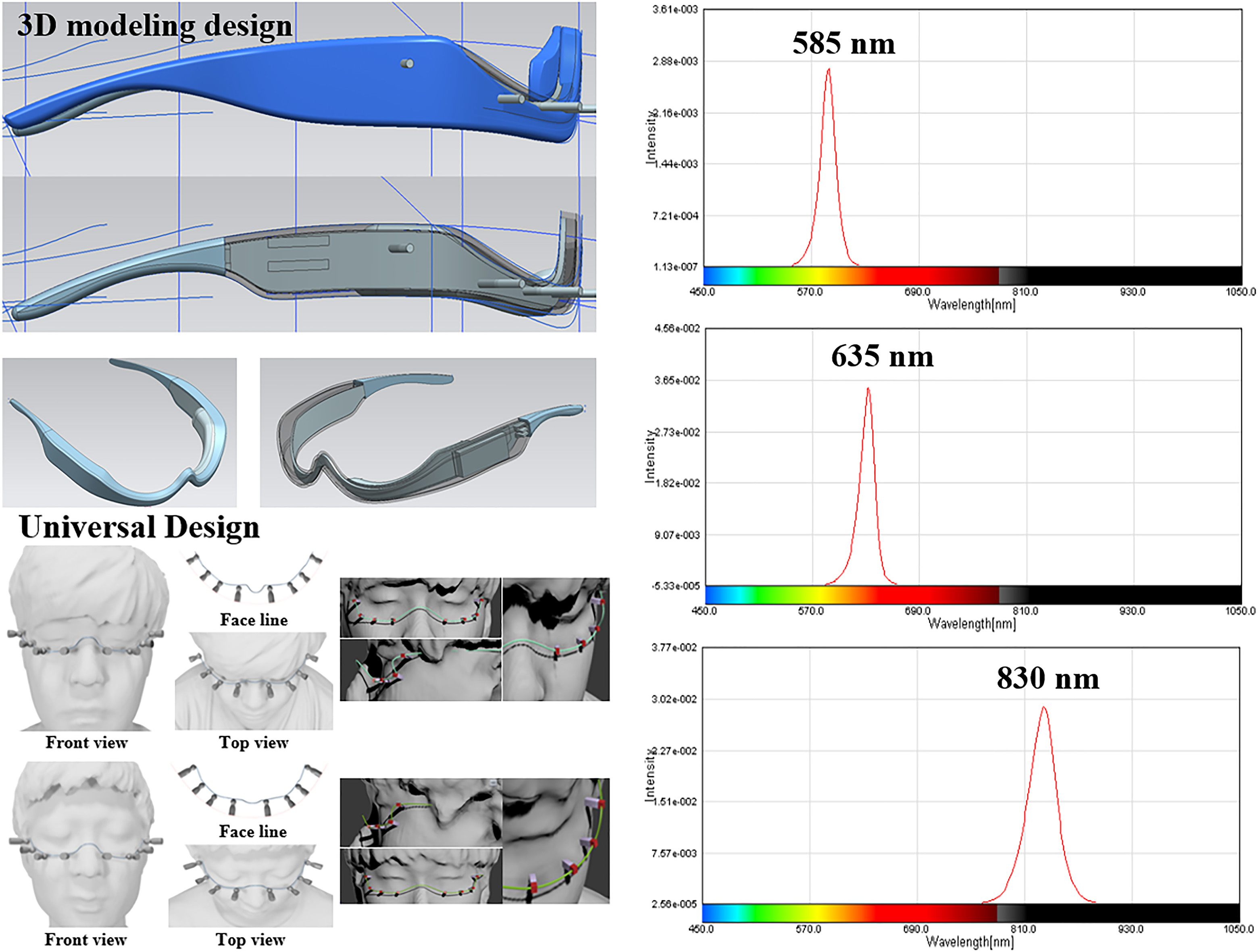
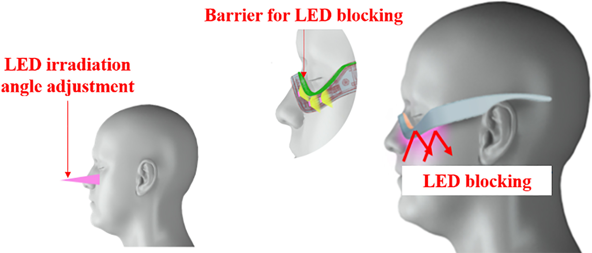
The position of the LED was selected after considering the average size of the human face and the impact of the irradiation angle and the irradiation amount of the LED according to the shape of the facial curves. To design the frame of the skin care device, a simulation was performed considering the position and size of the eyes and nose, which are closely related to wearability. The final 3D model was designed based on the universal design. The LED irradiation points were set around the eyes according to the size and shape of the face, and a screening film was designed to prevent direct LED irradiation or glare.
2.2Integrated LED optical module and prototype development
In our study, an integrated LED module was developed for effective skin irradiation and control of the wavelength of the LED. With this device, it is possible to use the eye-skin care glasses at four wavelengths – red, blue, yellow, and near infrared. Red wavelength (600–650 nm) can penetrate into the dermal tissue of the skin, stimulate the mitochondria, and activate ATP (Adenosine triphosphate) production, thereby inducing cellular turnover, superficial circulation, and anti-inflammatory emission [17, 18]. In addition, they promote the production of collagen and elastin, proteins that constitute the skin, which have effective anti-aging functions. Blue wavelength (390–470 nm) is absorbed by the epidermal tissue of the skin and stimulates porphyrin to produce more singlet oxygen in the cells to kill bacteria and attack cells and germs; thus, it is used to treat acne or seborrheic dermatitis [3].
Yellow wavelength (545–600 nm) has been reported to improve the composition of collagen, reduce MMP-1 and wrinkles, improve skin texture, and relieve redness of the skin. It is thought that the LED has a mechanism of down-regulating the MMP (Matrix metalloproteinases) stimulated by UV exposure, and this leads to anti-inflammatory and erythema reduction effects [9, 19, 20]. Infrared wavelength (780–940 nm) can penetrate deeper than other wavelengths and reach the dermal layer 2–3 mm into the skin [7]. The cells that absorb these wavelengths rise in temperature, which induces a pain-relieving effect that can be used for scar healing by aiding cell regeneration. In addition, this effect helps to suppress the secretion of sebum from the sebaceous glands [21] and increase the level of collagen fibers and elastin in the dermal layer to improve the skin texture [22].
Figure 1 illustrates the design of the 3D model and of a prototype using the model. In addition, an integrated LED optical module was fabricated for eye-skin care and the performance of the LED wavelength was verified as shown on the right side of Fig. 1. The LED wavelengths consist of 630 nm (red light), 415 nm (blue light), 590 nm (yellow light), and 830 nm (near-infrared light). In addition, the peak wavelength and radiance of each LED were measured to evaluate the performance of the developed LED module. The measurements were conducted at a position 3 cm away from the center of the sample. The peak wavelengths and its corresponding radiances were 632.9 nm and 0.47 W/m
Figure 2.
LED blocking barrier for the mechanical 3D design, prototype, and LED wavelength performance test.
3.Methods
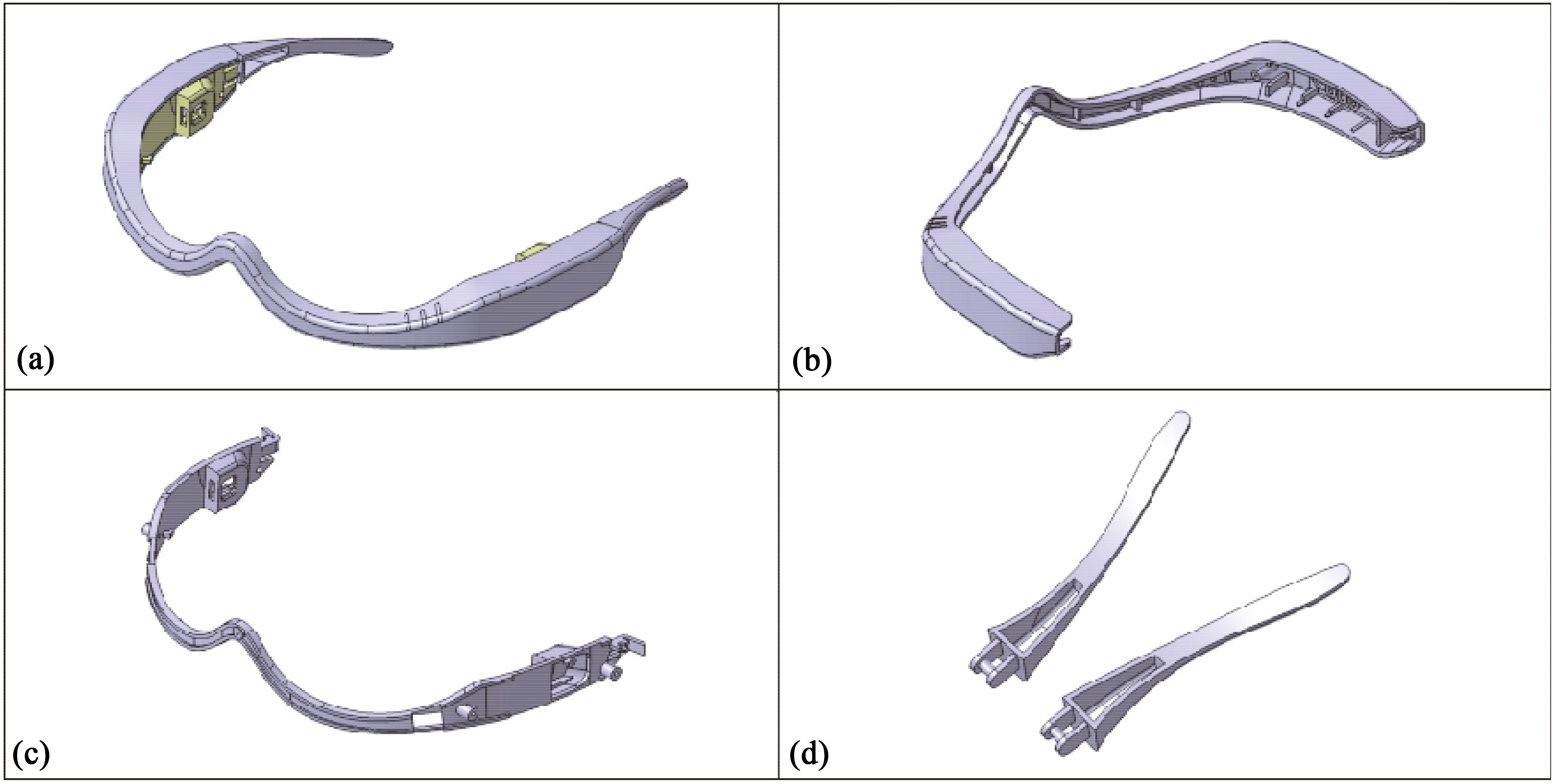
In this study, injection molding analysis was performed by dividing the model shown in Fig. 3a into three parts, as shown in Fig. 3b–d. The analysis was performed using the PC
Figure 3.
Design of the test model.
The analysis was performed by applying the PC
Figure 4.
Gate location conditions of the outer case.
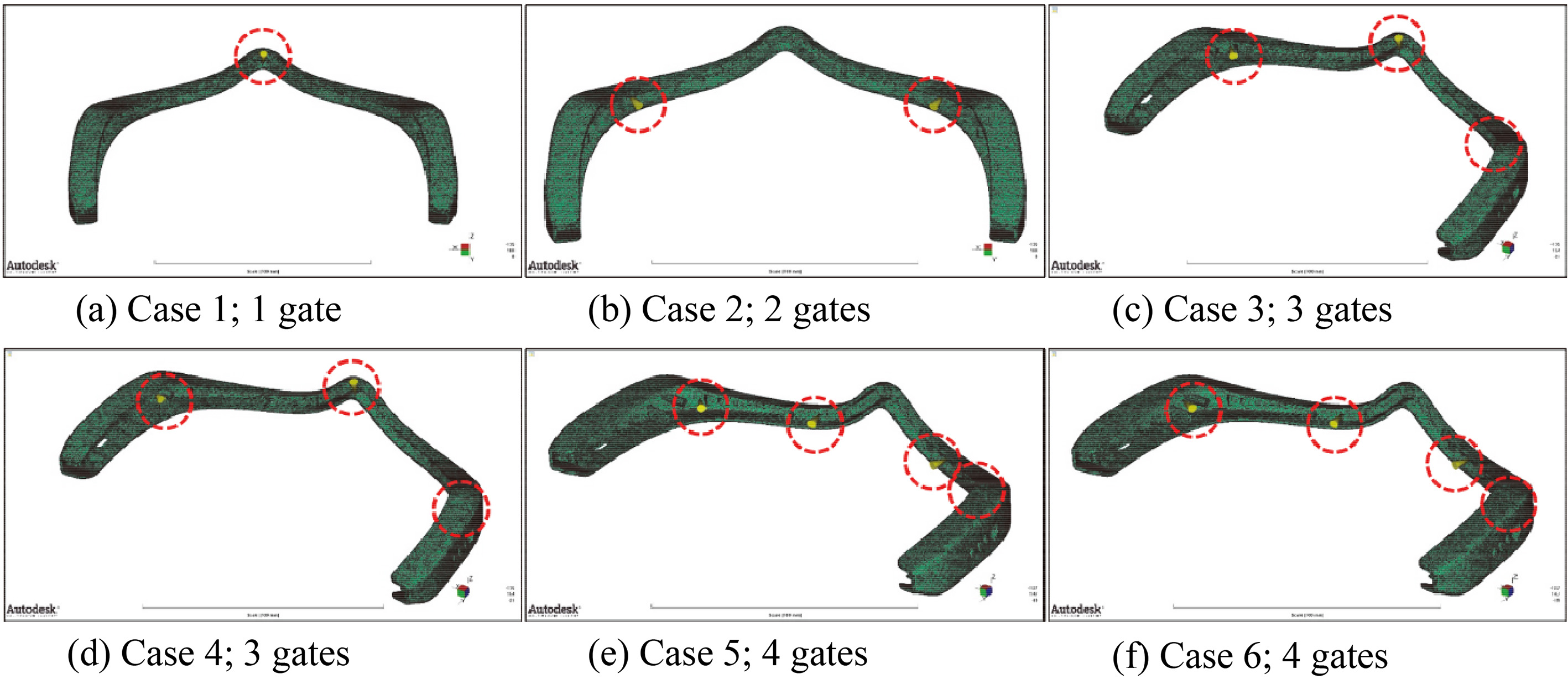
Next, the analysis was conducted by applying the PC
Figure 5.
Design of the inner part: (a) example of the combination with outer case, (b) thin inner part.
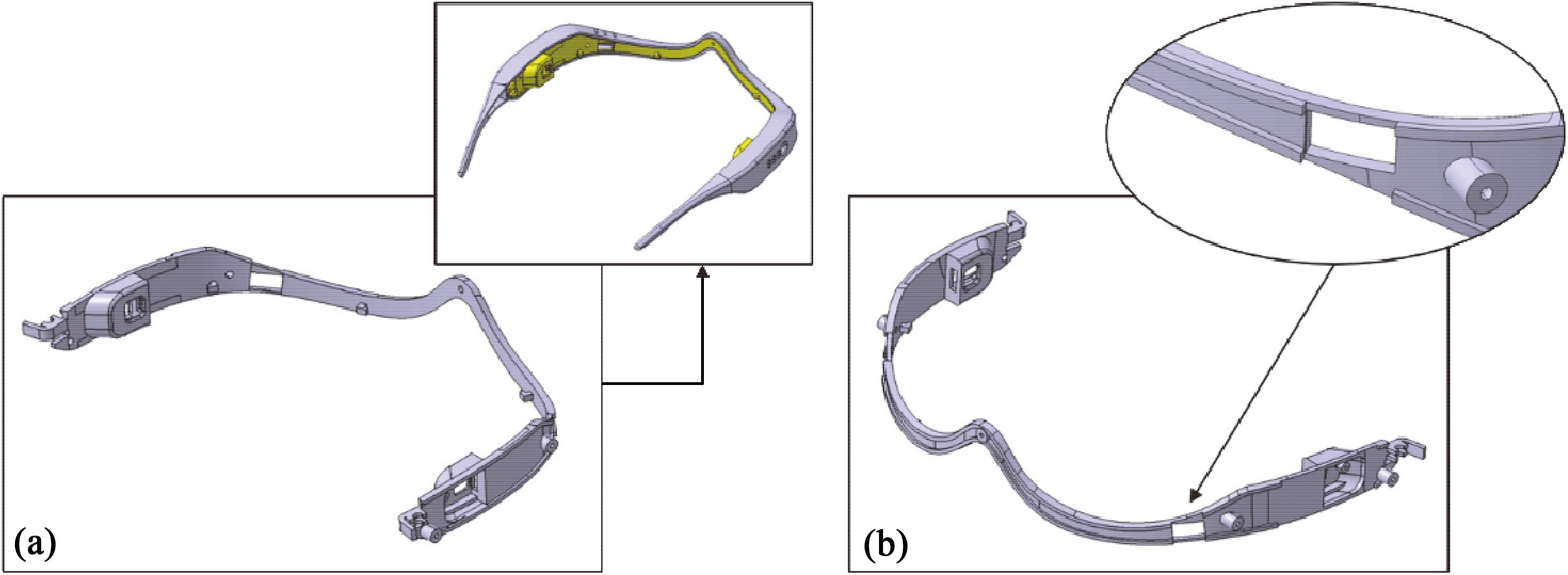
Figure 6.
Gate location conditions of the inner part.
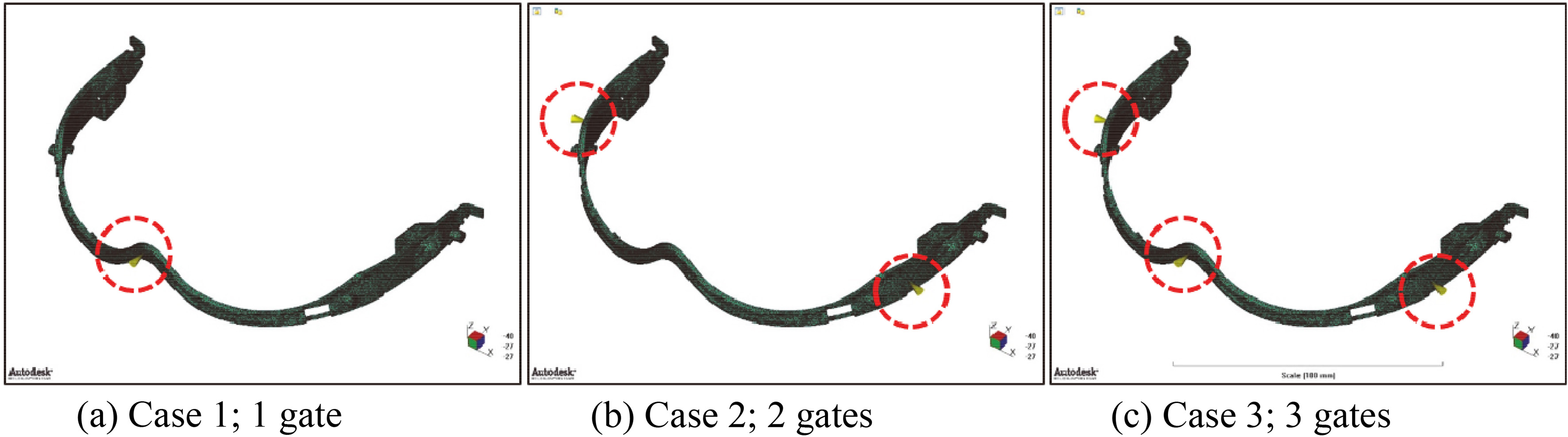
The model for the analysis was composed using 28,862 elements. As shown in Fig. 6, the analysis was conducted by considering a total of three gate conditions: Case 1 with one gate, Case 2 with two gates, and Case 3 with three gates. Each location of the gates is marked by red circles on each figure. The mold temperature and injection temperature were set as 70
Finally, the analysis was performed by applying the PC
Figure 7.
Gate location conditions of the temple.
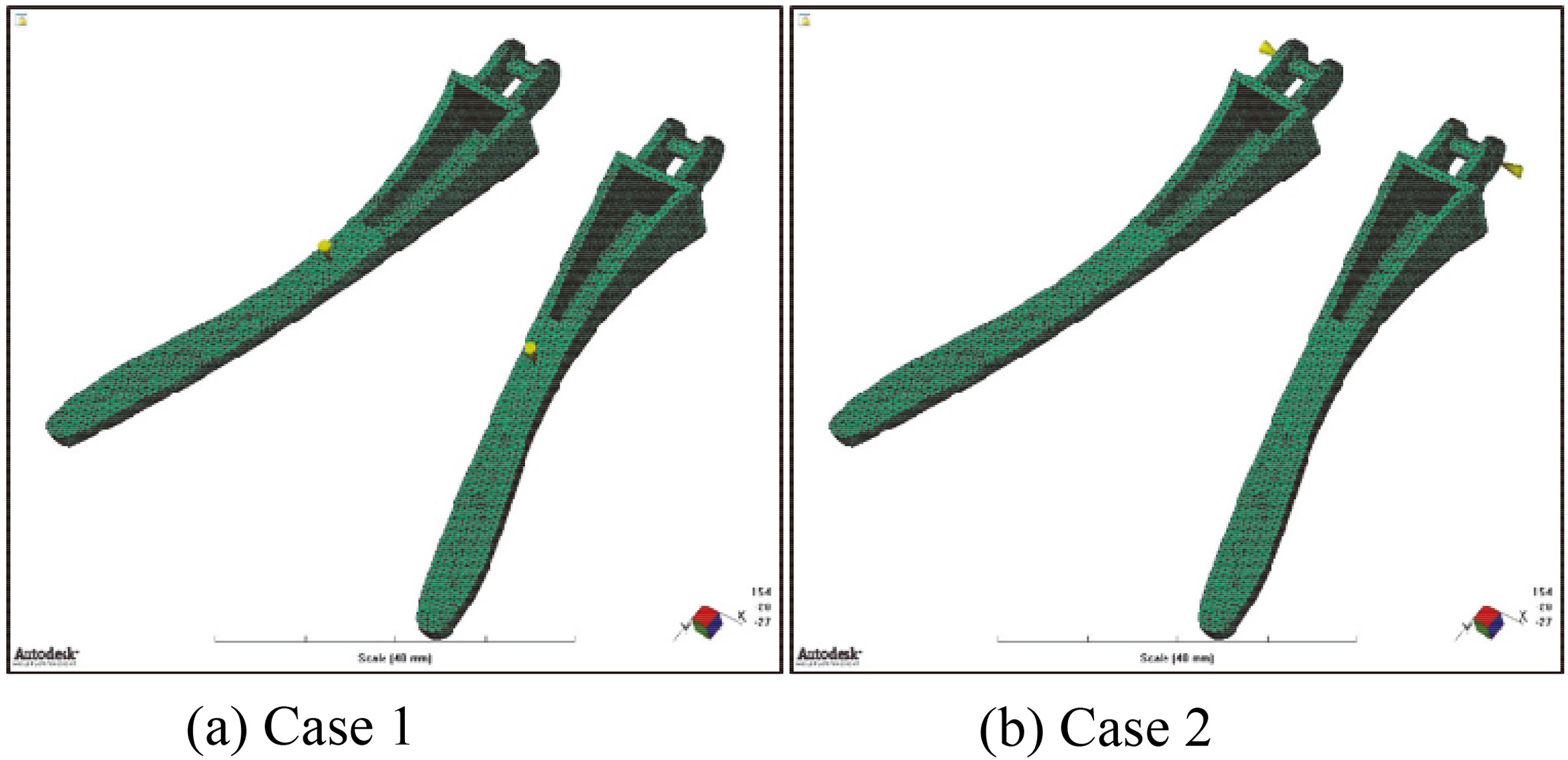
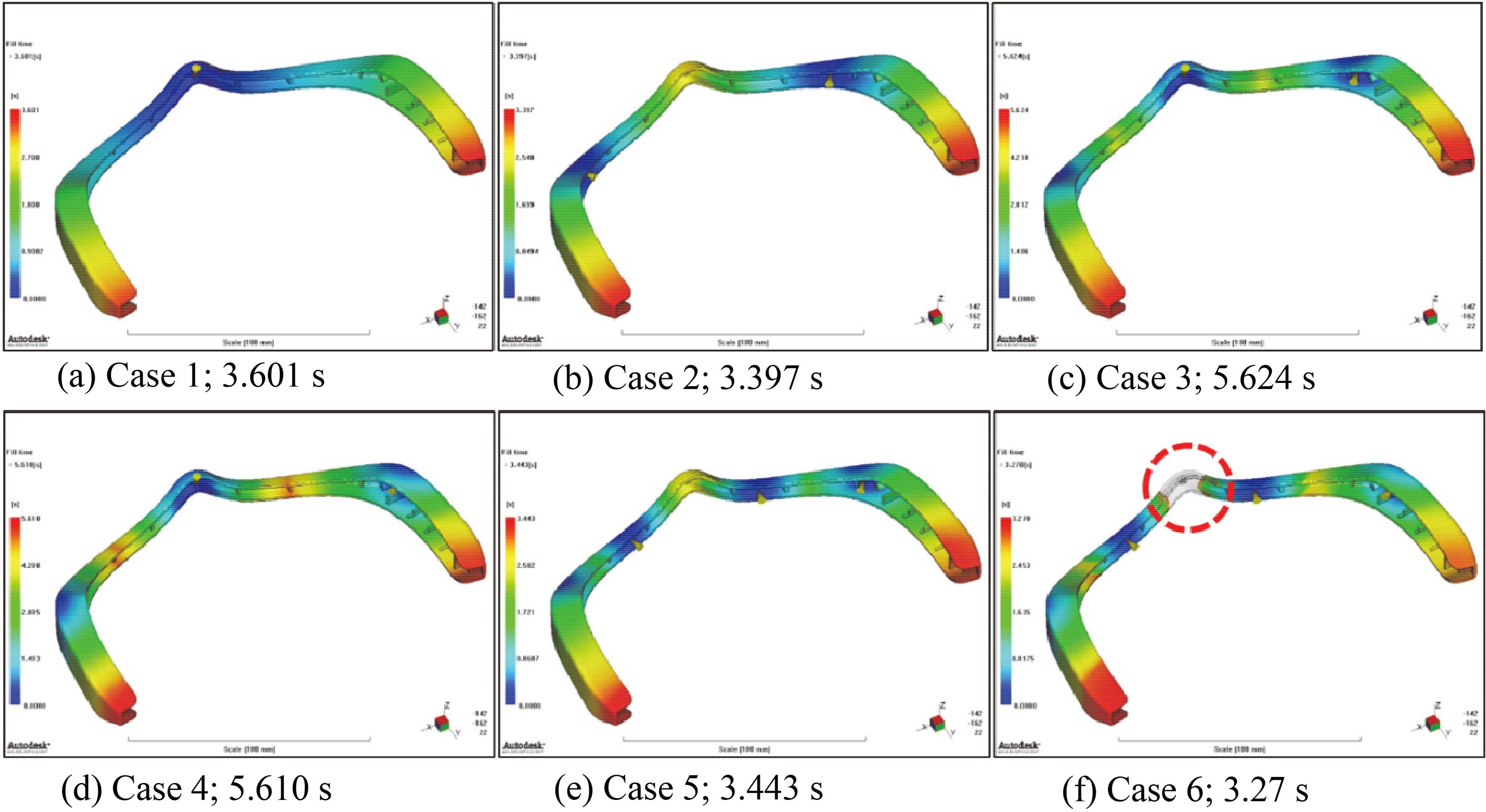
Figure 8.
Analysis results of fill time.
4.Results and discussion
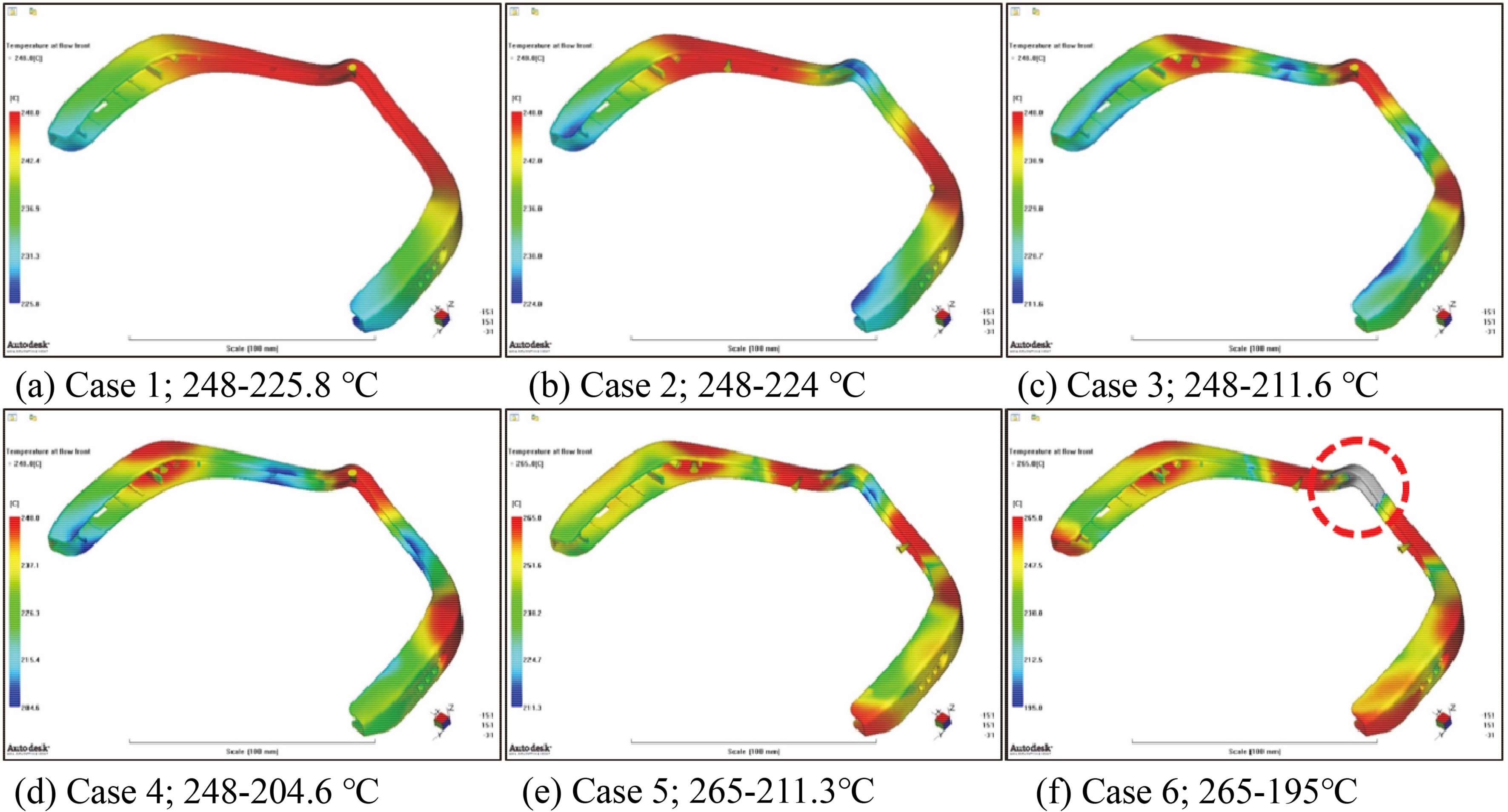
Figure 8 shows the results of the fill time distribution to identify the moldability in each case. The values of fill time are 3.601 s, 3.397 s, 5.624 s, 5.610 s, 3.443 s, and 3.27 s, respectively, in Cases 1 to 6. The fill time is the shortest in Case 6, but short shots are expected to occur. The end part of the device is wide, leading to plenty of resin being filled in it, and the central part is narrow, causing high pressure for the resin to be filled. Figure 9 shows the analysis results of the temperature change at the flow front. In Cases 1–6, the temperature decrease at the flow front is expected to be low due to the thin product and it is thought that there may be short shots in some places. The estimated short shot point is marked by red circle on both of Figs 8 and 9. In particular, in Case 6, the temperature at the flow front in the center is lowered to 195
Figure 9.
Analysis results of temperature at flow front.
Next, deflection analysis was performed for all cases except Case 6, which is expected to cause short shots; Figure 10 shows the results. As a result of the analysis, the degree of deflection is not expected to be large in terms of the product size, and the expected deflection size is 1.65 mm for large products and 0.78 mm for small ones. Finally, the injection pressure variation and clamp force were analyzed in each case. As in the deflection analysis, the pressure changes were analyzed in Cases 1–5, which is expected to cause short shots. Table 1 shows the results of the injection pressure analysis, which predicts the lowest pressure in Case 3. However, in this case, the injection pressure still exceeds 78 MPa and the moldability is not expected to be good at the first injection. And the table shows that the clamp force in all the cases is 60,000 kg or less.
Table 1
Results of analysis – outer case
| Materials | Case | Number of gates | Fill time (s) | Temperature at flow front ( | Deflection (mm) | Pressure (MPa) | Clamp force (t) |
|---|---|---|---|---|---|---|---|
| PC | 1 | 1 | 3.601 | 248–225.8 | 1.654–0.1184 | 137.3 | 58.2856 |
| 2 | 2 | 3.397 | 248–224 | 1.515–0.0341 | 86.63 | 43.0569 | |
| 3 | 3 | 5.624 | 248–211.6 | 0.9302–0.0767 | 77.94 | 30.3583 | |
| 4 | 3 | 5.610 | 265–204.6 | 1.277–0.0475 | 85.25 | 34.6740 | |
| 5 | 4 | 3.443 | 265–211.3 | 0.7852–0.1002 | 128.7 | 41.9819 | |
| 6 | 4 | 3.27 | 265–195 |
|
|
|
Figure 10.
Analysis results of deflection.
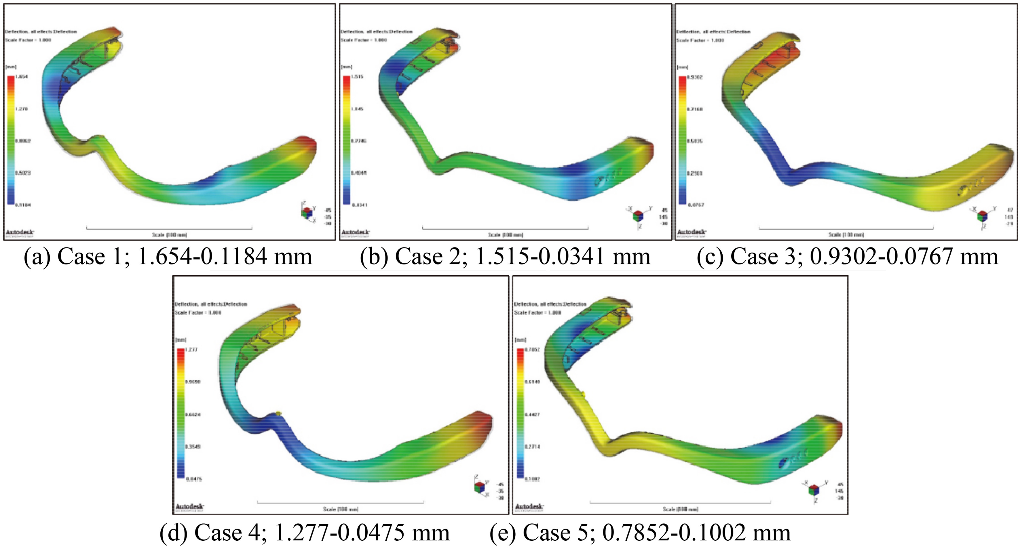
Figure 11.
Analysis results of fill time.
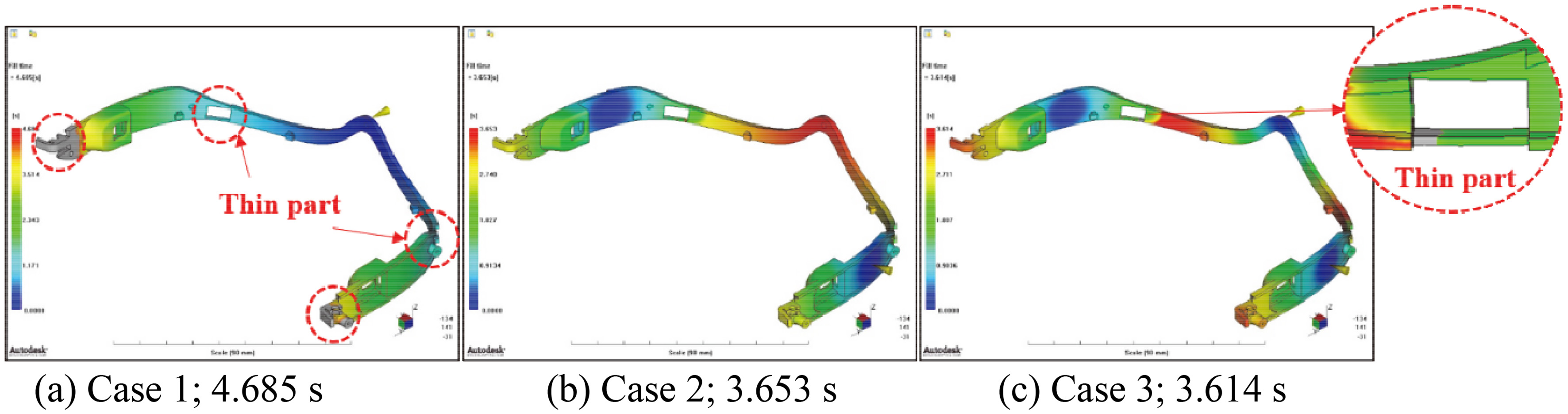
Figure 11 depicts the analysis results of the fill time distribution. As a result, the fill time in Cases 1–3 are 4.685 s, 3.653 s, and 3.614 s, respectively. In Case 1, short shots are likely to occur as the flow path of the cavity decreases rapidly in the thin part and high injection pressure is generated, and short shots are also expected to occur in the part connected to the temple. Similar to Case 1, Case 3 is also expected to cause short shots in the thin part, and a short shot is unlikely to occur in Case 2. In Cases 2 and 3, it is expected that a weld line is formed using multiple gates, which may reduce the device durability. Figure 12 depicts the analysis results of the temperature change at the flow front. The thin parts in Cases 1 and 3 are expected to cause short shots as the temperature at the flow front decreases to 191
Table 2
Results of analysis – inner part
| Materials | Case | Number of gates | Fill time (s) | Temperature at flow front ( | Deflection (mm) | Pressure (MPa) | Clamp force (t) |
|---|---|---|---|---|---|---|---|
| PC | 1 | 1 | 4.685 | 248.1–191 | 4.024–0.4351 | 137.3 | 7.7406 |
| 2 | 2 | 3.653 | 248–191 | 6.059–0.6869 | 110.7 | 13.3716 | |
| 3 | 3 | 3.614 | 248–191 | 5.586–0.6154 | 76.07 | 9.6054 |
Figure 12.
Analysis results of temperature at flow front.
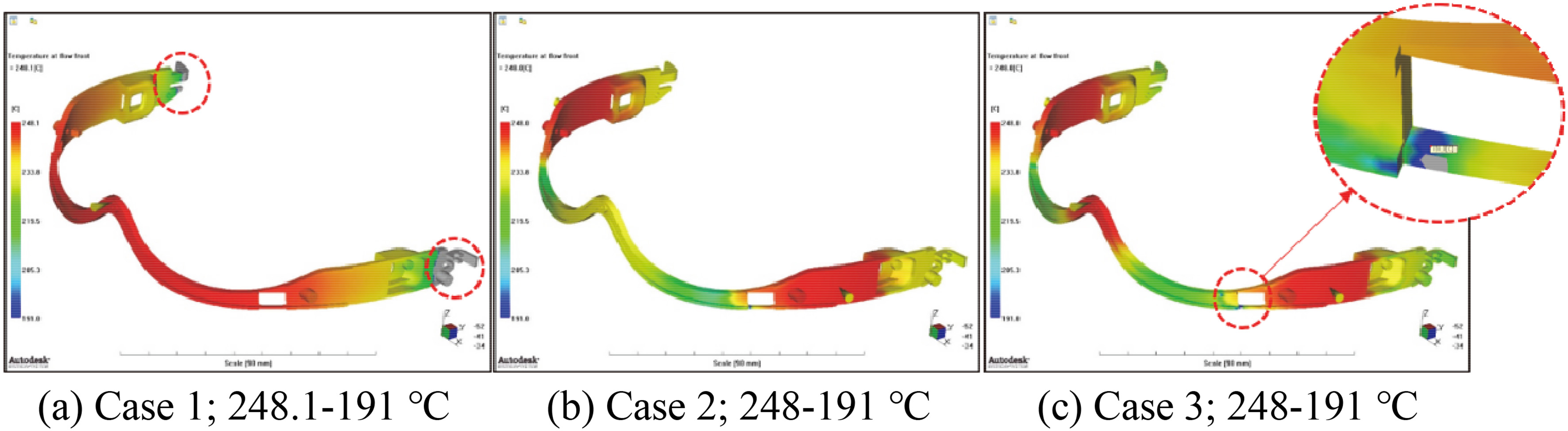
Figure 13.
Analysis results of deflection.
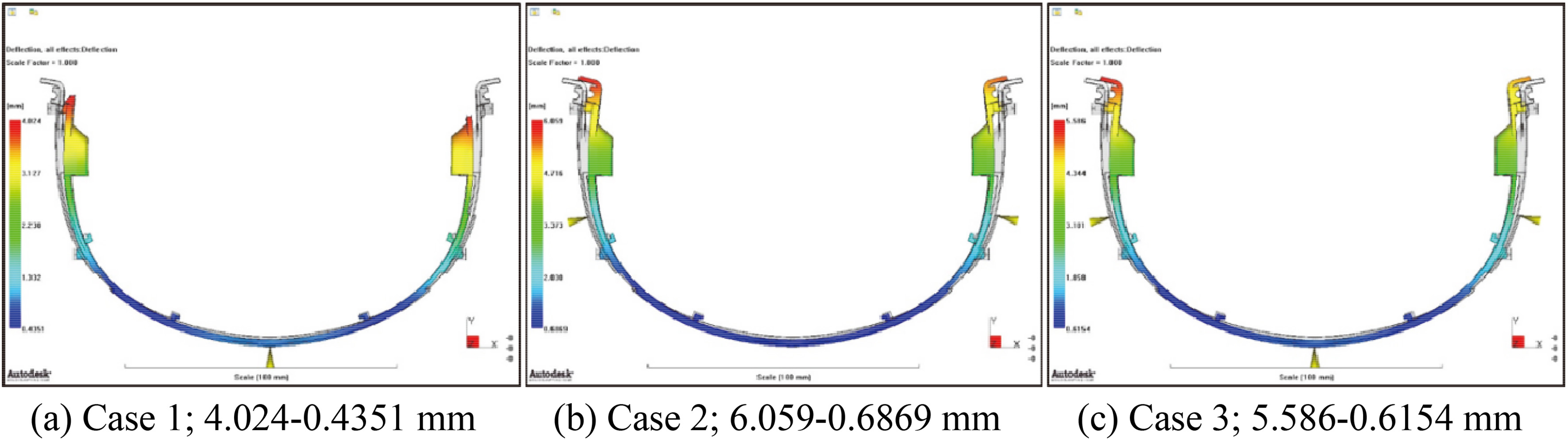
Next, deflection analysis was performed for each case. Figure 13 depicts the result of the deflection analysis, and the maximum deflection value is expected to be 6.059–0.6869 mm in Case 2. The inner part is U-shaped and it is expected that a deflection of the end parts connected to the portion of the temple bending inward may occur after the molding. However, this is not expected to have a significant effect on the connection of the outer case. Finally, the injection pressure variation and clamp force were analyzed in each case. Table 2 depicts the result of injection pressure analysis. In Case 2, the pressure rises at the fill end where the cavity space is thin. In addition, in Cases 1, 2, and 3, the injection pressure is expected to be 75 MPa or higher, which is likely to cause a large number of molding defects during the first molding. And the table shows that the clamp force in Cases 1, 2, and 3 is 60,000 kg or less.
Figure 14 shows the analysis results of the fill time distribution in each case. The analysis shows that the fill times in Cases 1 and 2 are 4.122 and 4.132 s, respectively. In Case 1, where the gate is located in the middle, flow stagnation is likely to occur for a short time in the section where the cavity in which the resin is filled narrows rapidly. In addition, if the gate is located at the end of the temple as shown in Case 2, it is considered that the resin will be filled without causing any disturbance in the flow pattern. Figure 15 shows the analysis results of the temperature change at the flow front. In Case 1, as the temperature at the flow front decreases in the section where the cavity narrows, the possibility of short shots increases due to flow stagnation.
Table 3
Results of analysis – temple
| Materials | Case | Number of gates | Fill time (s) | Temperature at flow front ( | Deflection (mm) | Pressure (MPa) | Clamp force (t) |
|---|---|---|---|---|---|---|---|
| PC | 1 | 2 | 4.122 | 248–197.3 | 0.4444–0.0239 | 36.06 | 2.5425 |
| 2 | 2 | 4.132 | 248–225.4 | 0.546–0.0185 | 47.10 | 1.9256 |
Figure 14.
Analysis results of fill time.
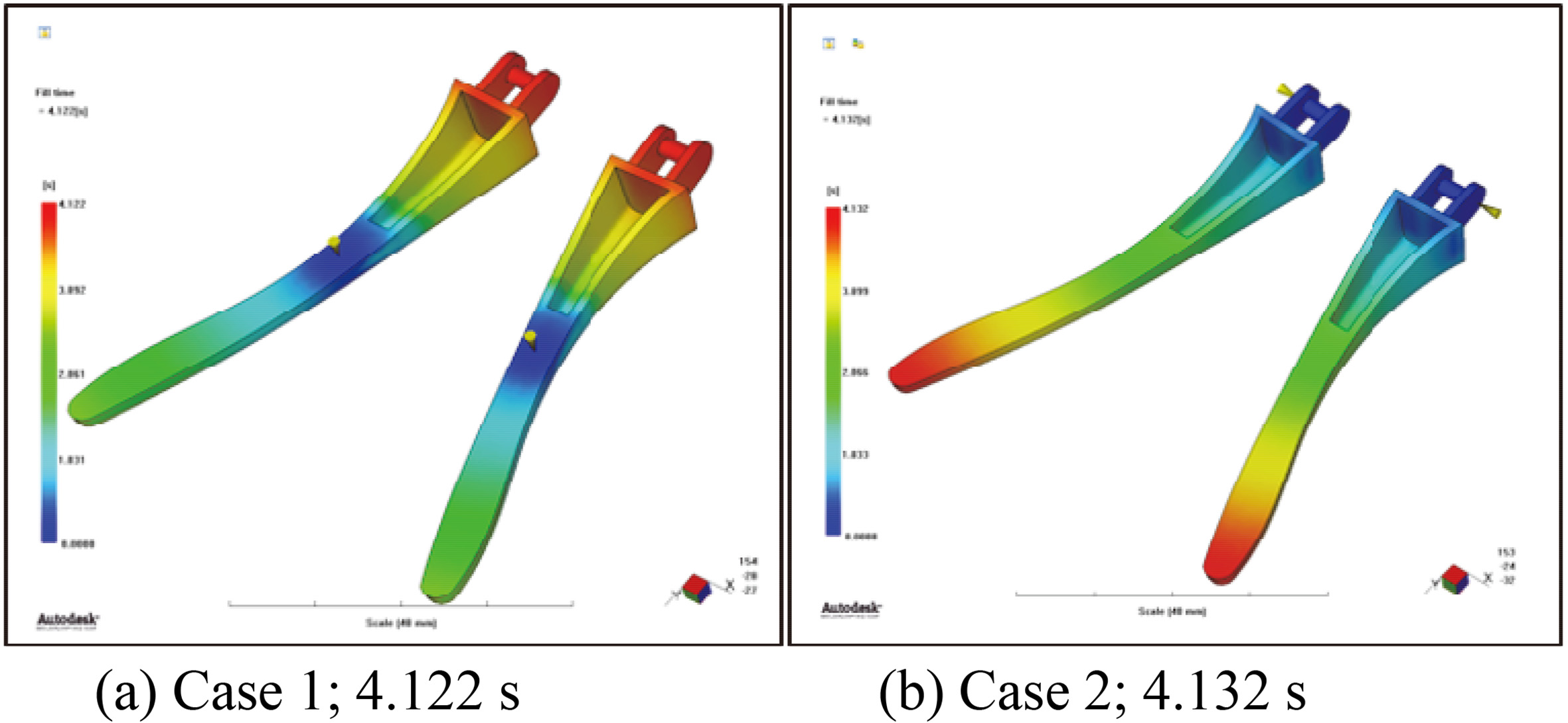
Figure 15.
Analysis results of temperature at flow front.
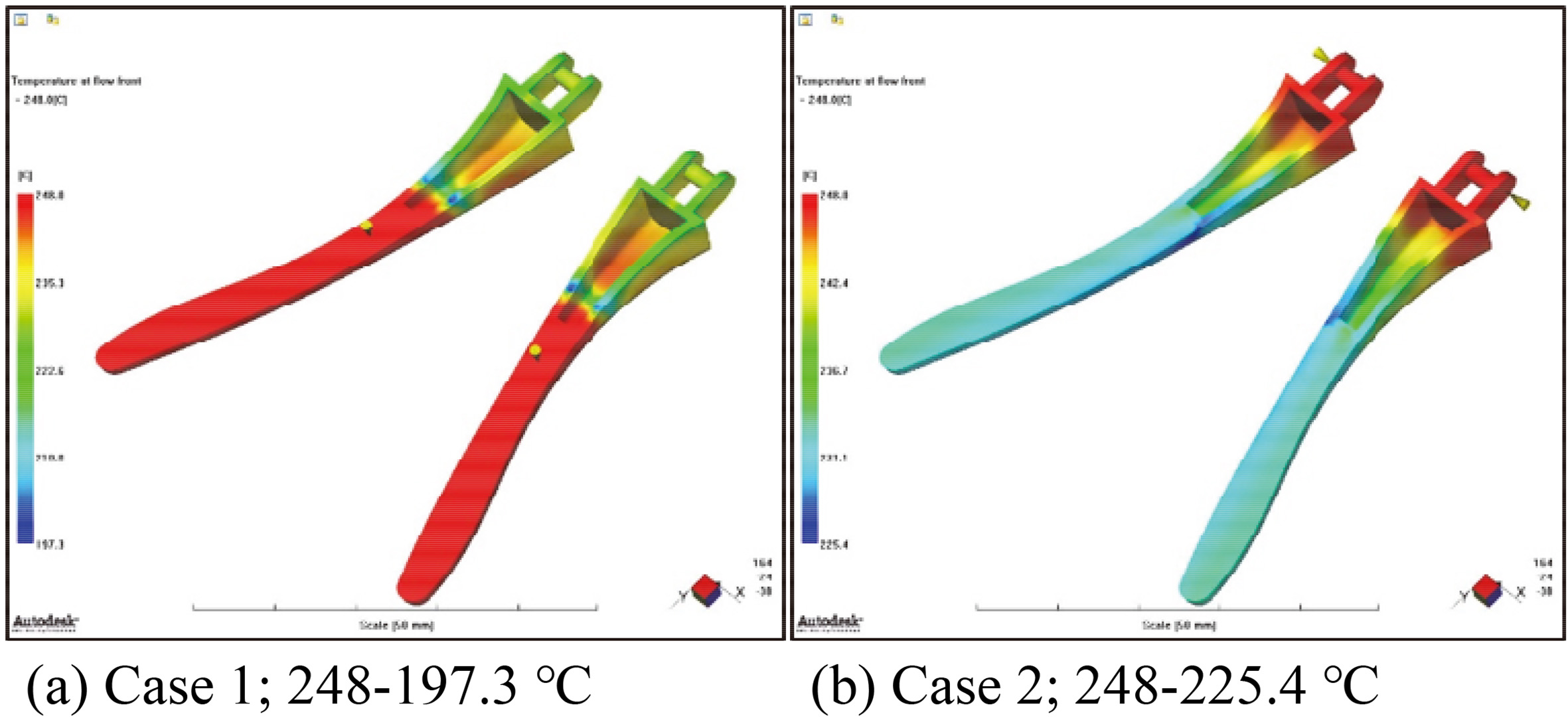
Figure 16.
Analysis results of deflection.
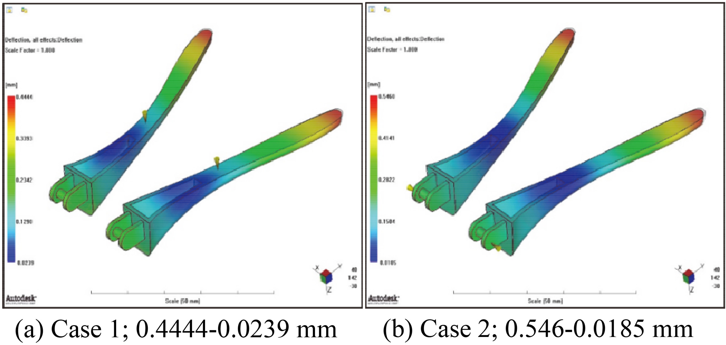
Next, deflection analysis was performed for each case. Figure 16 shows the results, and as the temple part is small in volume, the deflection according to the gate position is not expected to be large. Finally, the injection pressure changes and clamp force were analyzed for each case. Table 3 shows that the injection pressure is 50 MPa or less in Cases 1 and 2, which is not expected to cause any difficulty in the first molding. And the table shows that the clamp force in Cases 1 and 2 is 60,000 kg or less.
In this study, we developed a glasses-type facial skin care device with an integrated LED optical module and universal design. The optimum shape was designed by analyzing data related to the human body shape, and the LED light irradiation range was identified through simulation after selecting the ideal LED position based on the curves of the human face. Thereafter, the prototype was fabricated, used, and tested, and the integrated LED optical module technology was developed to enable the use of four wavelengths. Furthermore, injection molding analysis was performed for the design of the device mold. In the analysis, the device model was divided into three parts – outer case, inner part, and temple – and these were compared for fill time, temperature at the flow front, the extent of deflection, injection pressure, and clamp force. The injection molding analysis results of the outer case, inner part, and temple are shown in Tables 1–3, respectively.
The outer case was analyzed for each of the six cases, and it was predicted that short shots would occur in Case 6. The injection pressure exceeded 50 MPa in all the cases, and the moldability was not expected to be good at the first instance of injection. The outer case is composed of a thin film of thickness is less than 1.5 mm, and the injection pressure was expected to increase due to the small size of the space to be filled with the resin. It is essential to maintain the temperature at the flow front of the resin and to change the design later because the product shape designed is such that it is difficult to separate from the mold. Based on the injection molding analysis of the inner part, short shots are expected in Cases 1 and 3. In addition, the injection pressure decreases as the number of gates increases; however, the maximum injection pressure in Case 3 with three gates is 76.07 MPa, which is expected to increase the possibility of short shots at the first molding. Furthermore, similar to the outer case, the inner part has a narrow fill space, and there is a section in which short shots are likely to occur, which requires a change in the design in the future. For the molding analysis of the temple part, Case 1, with the gate positioned at the center part, showed the pattern of the resin introduced from the gate flowing through the narrow cavity and stalling in the middle before the filling. In Case 2, with the gate located at the end part, the resin is expected to be filled without any obstruction in the flow pattern and, as the injection pressure was analyzed to be 50 MPa or less, it is expected to show good moldability.
5.Conclusion
In this study, a prototype of a glasses-type skin care device with LED irradiation function was developed and injection molding analysis was performed using a design for mass production. The product was designed by implementing a universal design to increase the wearability of the skin care device in the form of glasses. The first prototype of the skin care device was designed along with the integrated LED optical module capable of irradiating at three LED wavelengths to study the structural function of the product. The prototype of the skin care device developed was divided into three mechanisms for the injection molding analysis. For the outer case and inner part, it is essential to maintain the temperature at the flow front of the resin because of increasing injection pressure due to the narrow space where the resin is filled. As the current design makes it difficult to separate the product shape from the mold, it is concluded that the design needs further modification later on. The temple part is expected to be filled with resin without any difficulty in the flow pattern, and the moldability is also expected to be good, as the injection pressure was analyzed to be 50 MPa or less. In future work, the 3D prototype will be modified to enable injection molding analysis using other materials as well as PC
Acknowledgments
This work was supported by Basic Science Research Program through the National Research Foundation of Korea (NRF) funded by the Ministry of Education (2018R1D1A3B07049251).
Conflict of interest
None to report.
References
[1] | Kim KO, Jang YS. The ion effect of facial portions by galvanic current in the 20’s women. Journal of Investigative Cosmetology. (2007) ; 3: (1): 39-50. |
[2] | Lee J, Kim CH, Chung GH. Development of a personal compound stimulus device for skin-care. Journal of the Institute of Electronics Engineers of Korea SC. (2012) ; 49: (1): 12-19. |
[3] | Lee YJ, Kwon YJ, Kim KH. Technology commercialization strategy of hand-machine for skin care made LLLT. Technology Management. (2018) ; 3: (1): 71-118. |
[4] | Kim SJ. A study on the optimization of the skin care by multiwavelength light sources. Doctoral thesis, University of Mokwon, Daejeon, Korea, (2016) . |
[5] | Lee SY, Lee TH, Ju CL, Na HS, Lee IS, Park CW. Development of evaluation methods for the performance of infrared light irradiator by personal. The Korean Society of Food, Drug, and Cosmetic Regulatory Sciences. (2017) ; 12: (1): 93-100. |
[6] | Kalka K, Merk H, Mukhtar H. Photodynamic therapy in dermatology. Journal of the American Academy of Dermatology. (2000) ; 42: (3): 389-413. |
[7] | Avci P, Gupta A, Sadasivam M, Vecchio D, Pam Z, Pam N, Hamblin MR. Low-Level Laser(Light) Therapy (LLLT) in Skin: Stimulating, healing, restoring. Seminars in Cutaneous Medicine and Surgery. (2013) ; 32: (1): 41-52. |
[8] | Suck TS, Choi SY, Kim YC. Inhibitory effect of LED light irradiation on the wrinkle formation in hairless mouse. The Journal of Cosmetological Science. (2010) ; 6: (4): 347-356. |
[9] | Weiss RA, McDaniel DH, Geronemus RG, Weiss MA. Clinical trial of a novel non-thermal LED array for reversal of photoaging: clinical, histologic, and surface profilometric results. Lasers in Surgery and Medicine. (2005) ; 36: (2): 85-91. |
[10] | Russell BA, Kellett N, Reilly LR. A study to determine the efficacy of combination LED light therapy (633 nm and 830 nm) in facial skin rejuvenation. Journal of Cosmetic and Laser Ther apy: Official Publication of the European Society for Laser Dermatology. (2005) ; 7: (3-4): 196-200. |
[11] | Baez F, Reilly LR. The use of light-emitting diode therapy in the treatment of photoaged skin. Journal of Cosmetic Dermatology. (2007) ; 6: (3): 189-194. |
[12] | Lee SY, Park KH, Choi JW, Kwon JK, Lee DR, Shin MS, et al. A prospective, randomized, placebo-controlled, double-blinded, and split-face clinical study on LED phototherapy for skin rejuvenation: clinical, profilometric, histologic, ultrastructural, and biochemical evaluations and comparison of three different treatment settings. Journal of Photochemistry and Photobiology B. (2007) ; 88: (1): 51-67. |
[13] | Kim JM, Kim NH, Tian YS, Lee AY. Light-emitting diodes at 830 and 850 nm inhibit melanin synthesis in vitro. Acta Derm Venereol. (2012) ; 92: (6): 675-680. |
[14] | Menezes S, Coulomb B, Lebreton C, Dubertret L. Non-coherent near infrared radiation protects normal human dermal fibroblasts from solar ultraviolet toxicity. The Journal of Investigative Dermatology. (1998) ; 111: (4): 629-633. |
[15] | Frank S, Oliver L, Lebreton-De Coster C, Coreau C, et al. Infrared radiation affects the mitochondrial pathway of apoptosis in human fibroblasts. The Journal of Investigative Dermatology. (2004) ; 12: (5): 823-831. |
[16] | Shin MY, Son ID, Park SY, Chong WS, Yu CH. Development of portable glasses typed device for faical skin care with integrated LED optical module. Journal of Rehabilitation Welfare Engineering & Assistive Technology. (2019) ; 13: (2): 192-198. |
[17] | Young S, Bolton P, Dyson M, Harvey W. Macrophage responsiveness to light therapy. Lasers in Surgery and Medicine. (1989) ; 9: (5): 497-505. |
[18] | Corazza AV, Jorge J, Kurachi C, Bagnato VS. Photobiomodulation on the angiogenesis of skin wounds in rats using different light sources. Photomedicine and Laser Surgery. (2007) ; 25: (2): 102-106. |
[19] | McDaniel DH, Weiss RA, Geronemus RG, Mazur C, Wilson S, Weiss MA. Varying ratio of wavelengths in dual wavelength LED photomodulation alters gene expression profiles in human skin fibroblasts. Lagers in Surgery and Medicine. (2010) ; 42: : 540-545. |
[20] | Moon KR, Kwon HH, Suh DH, Yun SJ, Lee SC, Lee JB. The effectiveness of light emitting diodes with 592 nm yellow light for Korean photoaged skin. Korean Journal of Dermatology. (2015) ; 53: (9): 677-683. |
[21] | Rotunda AM, Bhupathy AR, Rohrer TE. The new age of acne therapy: light, lasers, and radiofrequency. Journal of Cosmetic and Laser Therapy. (2004) ; 6: (4): 191-200. |
[22] | Lee JH, Roh NR, Lee KH. Effects of infrared radiation on skin photoaging and pigmentation. Yonsei Medical Journal. (2006) ; 47: (4): 485-490. |


