
Analysis and control of biped robot with variable stiffness ankle joints
Abstract
BACKGROUND:
Biped robot locomotion is an active topic of research, and the walking stability is one of the research objectives.
OBJECTIVE:
This paper discusses the variable stiffness ankle joint and the walking control of a biped robot.
METHODS:
A design is introduced that achieves the ankle joint variable stiffness by using a pneumatic unit. The actuation system of the biped robot is based on the hybrid use of electric and pneumatic. The locomotion control architecture has been proposed to exploit natural leg dynamics in order to improve the biped robot walking stability. We also present a dynamic simulation which matches the biped robot and experiments with the real biped robot.
RESULTS:
The simulation and experiments result that introducing the variable stiffness ankle joint and the controller achieve a significant improvement in foot-ground impact and walking stability of the biped robot.
CONCLUSION:
The biped robot with variable stiffness ankle joints has a better walking performance under the control method.
1.Introduction
A biped robot applied in the natural and unstructured environment should have the real human motion abilities. Many terrains in the real world are inaccessible by the wheeled vehicles [1], but humans can walk in almost all terrains with their own legs. Legged vehicles, similar to the natural creatures, are the best choice for field missions in the natural environment [2]. A key feature of the human system is the biomechanical compliance of the joint. And the compliance of the joint is the ability of the structure to deform in response to external stresses [3]. I In pervious researches, it was shown that the elastic ankle joint can use passive dynamics to assist the push away movement at the later stage of single support and reduce the dissipative collision losses during the contralateral heel strike [4, 5]. It has also been demonstrated that the ankle stiffness helps robot achieve dynamic biped walking and reduces energy expenditure [6, 7].
Actuation with variable stiffness has been introduced as a solution to make the robot joints compliant. Compliant actuators generally include springs in series with stiff actuators. These elements can include fixed intrinsic stiffness (Series Elastic Actuators, SEA), or variable stiffness (Variable Stiffness Actuators, VSA) [8]. For the example there are the Actuator with Mechanically Adjustable Series Compliance (AMASC) [9], the Actuator with Adjustable Stiffness-II (AwAS-II) [10], the Continuous-state Coupled Elastic Actuator (CCEA), and the Actuator with Variable Stiffness and Torque Threshold (AVASTT) [11].
However, these actuators are large in size and weight, relatively. Therefore, the pneumatic actuator for the ankle joints is proposed in this paper. We first study the mechanisms and the design for variable stiffness ankle joints. Then the variable ankle joints controller is introduced in the biped robot control system. We also show the data from simulations and experiments of the platform.
2.Design of the variable stiffness ankle joints
A pneumatic unit is introduced to the ankle joint, the mechanism is shown in Fig. 1a. The prototype of biped robot is shown in Fig. 1b. The abstract model of the ankle joint is shown in Fig. 1c.
Figure 1.
Design of the variable ankle joint. (a) Components used in the ankle joint. (b) Prototype of biped robot. (c) Abstract model of the ankle joint.
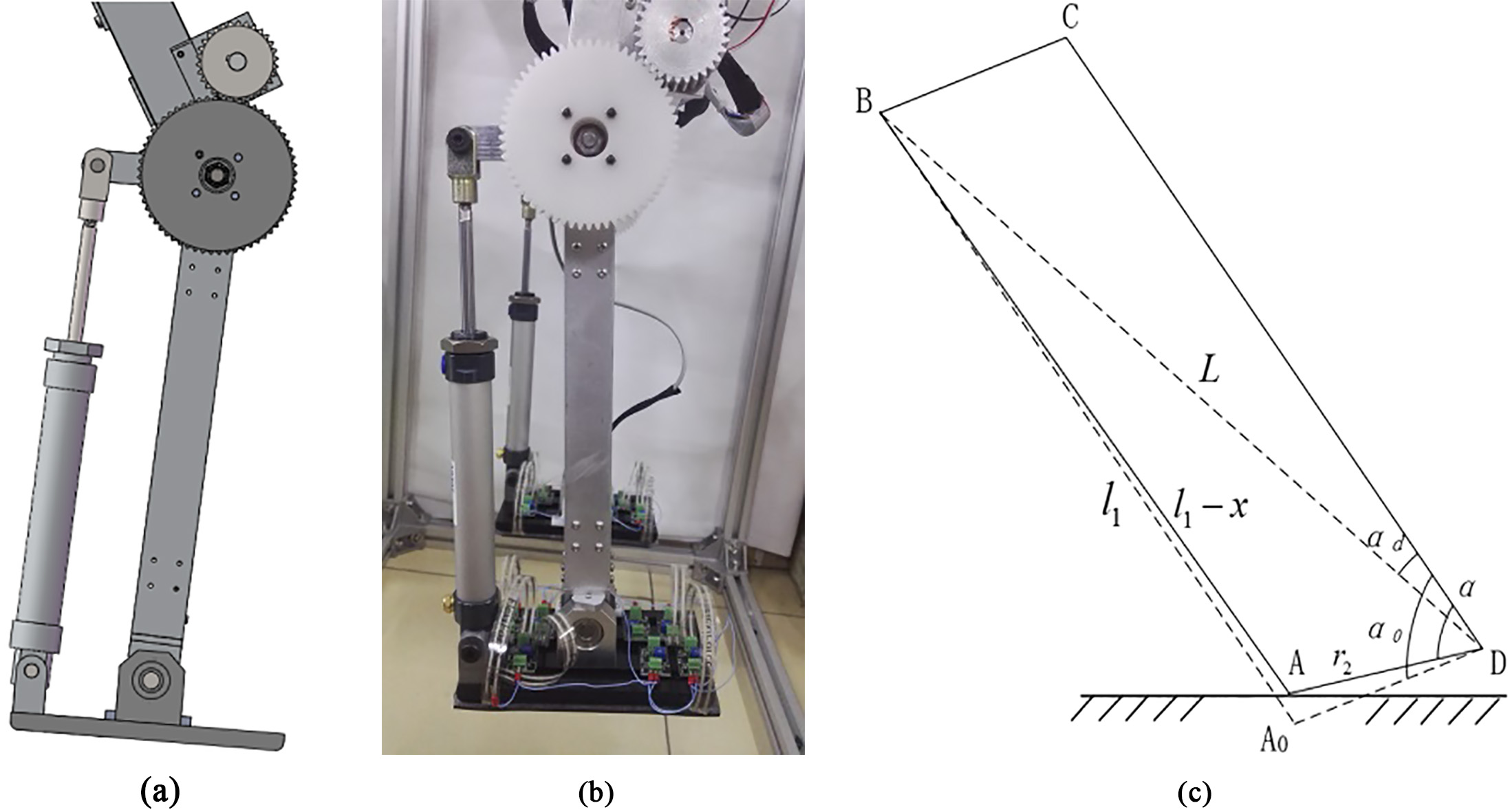
According to cosine theorem there are:
(1)
The force
(2)
The stiffness can be derived from:
(3)
3.Control schemes
3.1Variable stiffness ankle joint controller
On the basis of linear inverted pendulum model, the foot and ankle joint of the support leg are added to establish the biped robot support leg model, as shown in Fig. 2.
Figure 2.
Biped robot support leg model.
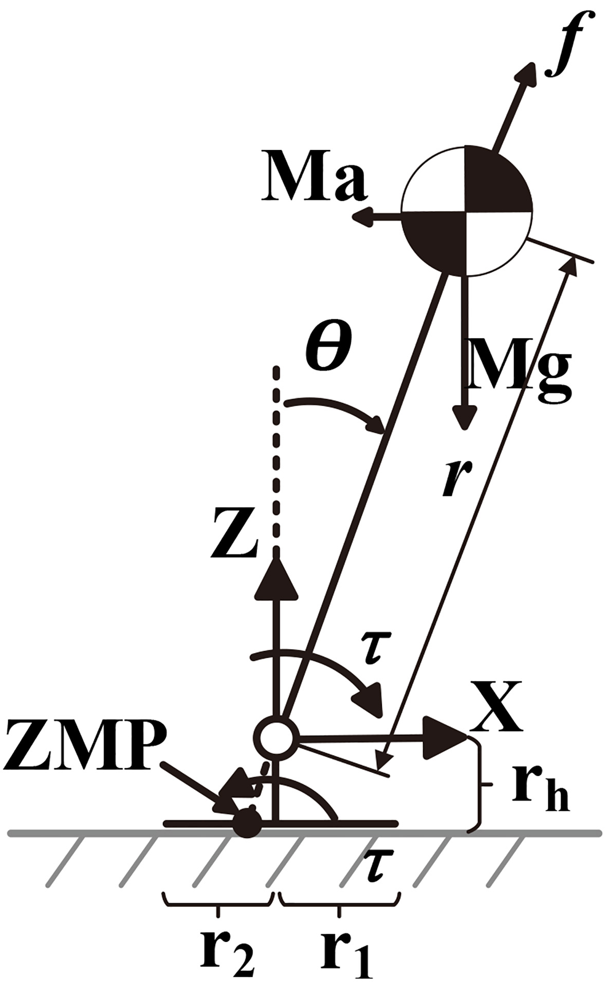
The equilibrium equation of the model can be expressed as:
(4)
Where
(5)
Where
Due to the flexibility of the variable stiffness ankle joint, the real angle
(6)
(7)
Where
(8)
(9)
Design the evaluation function of tracking error
(10)
Where
(11)
Where
(12)
3.2Overall control structure
Based on the position control, the hip and knee joint controllers are designed as:
(13)
Where
After the swing leg touches the ground, the stiffness of the ankle joint is changed and the motor output angle is not equal to the ankle joint real angle:
(14)
Figure 3.
Overall control structure of the biped robot.
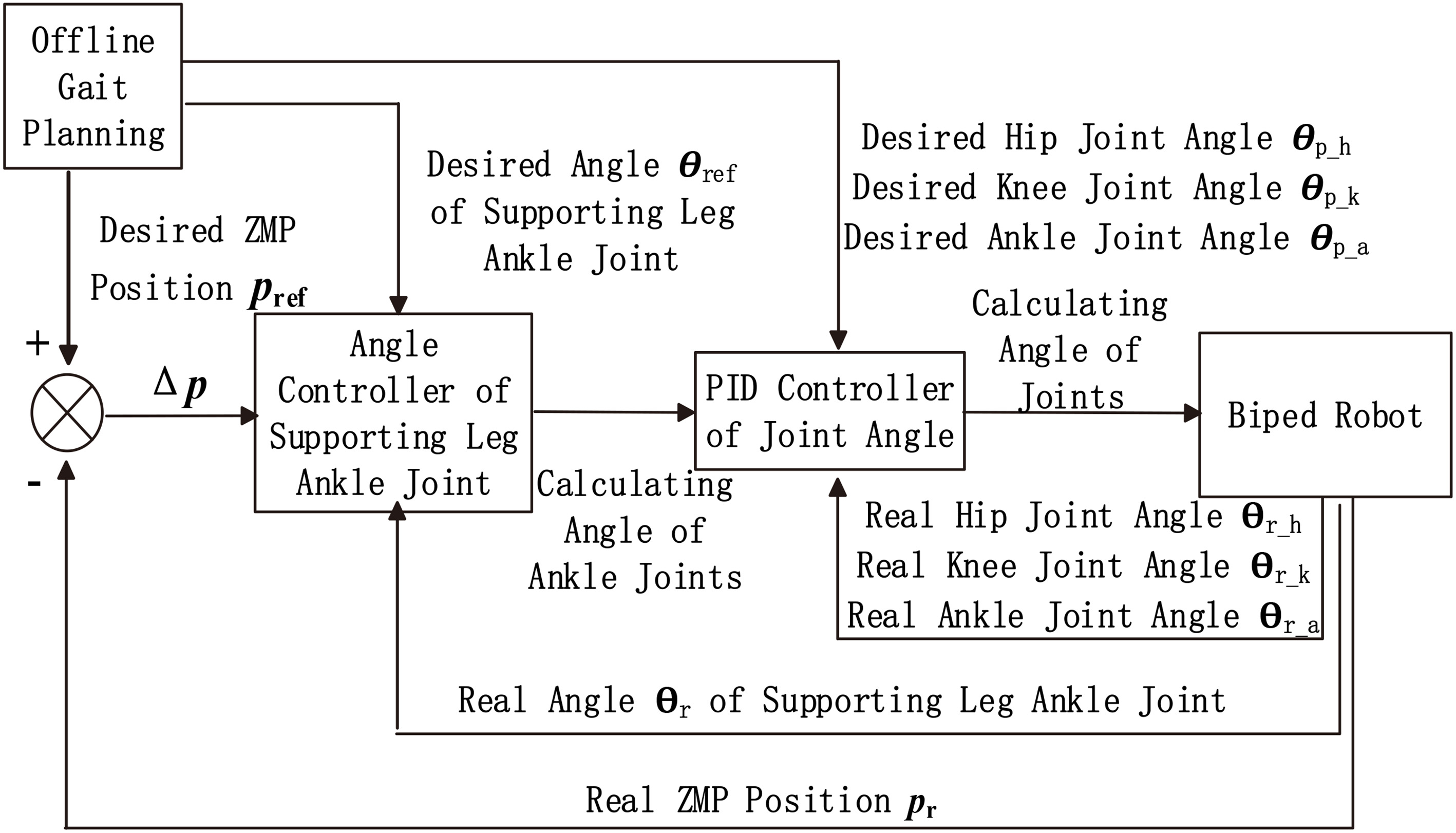
Where
4.Simulations
4.1Simulation settings
A simplified virtual prototype model of the biped robot is established to verify the gait planning and control strategy of the biped robot by using Adams (a multibody dynamics simulation solution software). The basic parameters of the robot model is set as shown in Table 1. The dynamic simulation of the biped robot walking is carried out several times, and the optimal stiffness of the ankle joint under the current gait planning is determined as
Table 1
Basic parameters of the robot model
| Robot | Length (mm) | Weight (kg) |
|---|---|---|
| Torso | 200 | 3 |
| Thigh | 279 | 2.5 |
| Shank | 298 | 1 |
| Foot | 160 | 0.75 |
| Total | 560 | 11.5 |
Figure 4.
Dynamic simulation process of the biped robot.
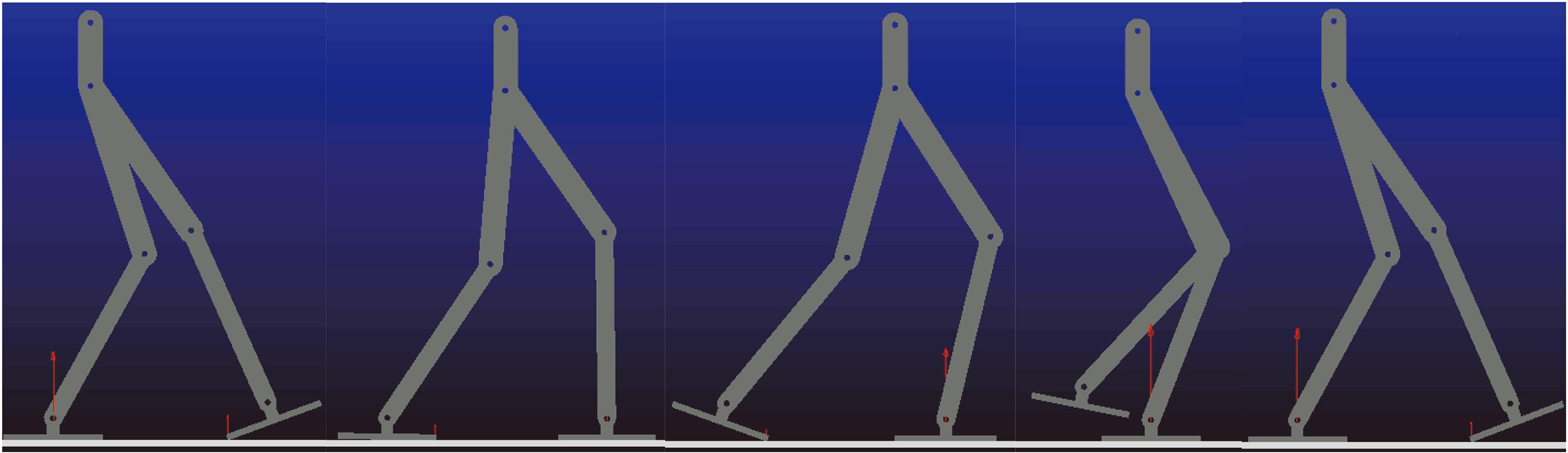
Figure 5.
Vertical force on foot-ground interface of biped robot with rigid ankle joint.
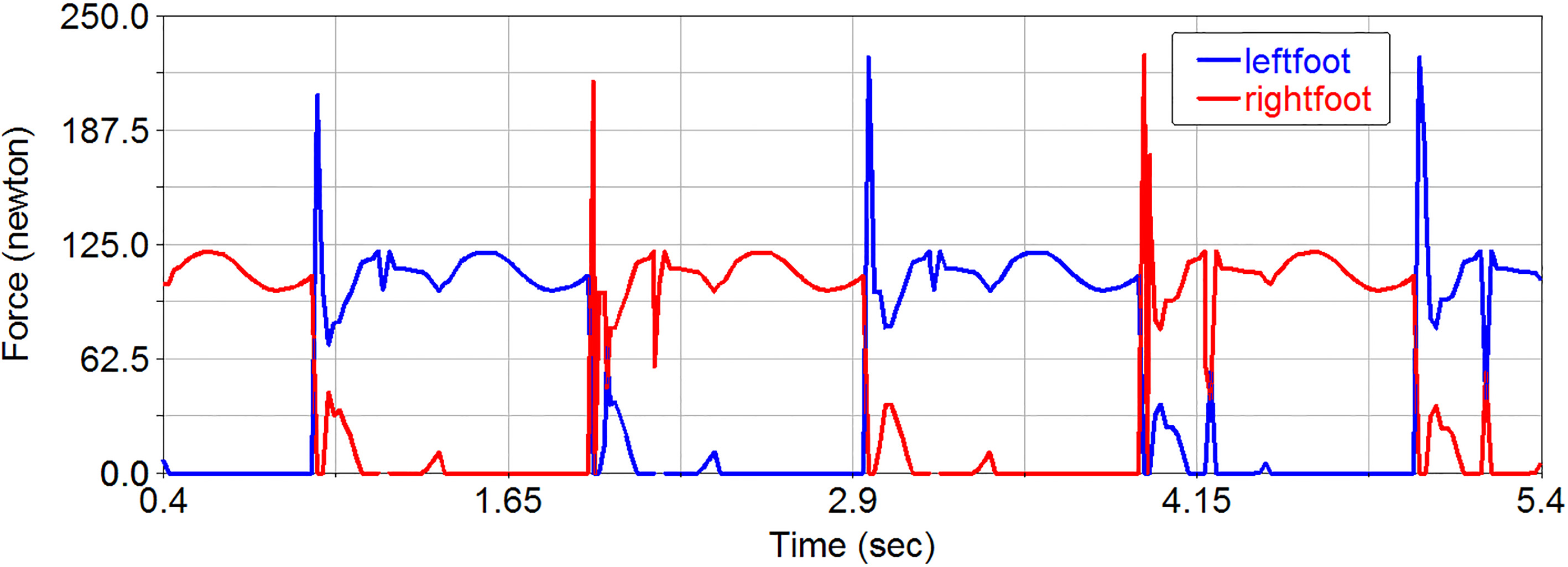
4.2Simulation results
Figures 5 and 6 show the simulation results of the vertical force on foot-ground interface. Figure 5 shows the force simulation result of biped robot with rigid ankle joint. It can be seen form the figure that the force on foot-ground interface has obvious abrupt change at the time of foot-ground collision, take the left foot as example, the force increases steeply to about 206 N at the heel collision time and increase from about 70 N to 121 N at the toe collision time. Meanwhile, the force of right foot drops from 108 N to 0 N steeply. After introducing the variable stiffness ankle joint controller, as shown in Fig. 6, the left foot force on foot-ground interface is about 100 N at the time of heel collision, but quickly decreased to about 20 N, and then the force increases steadily until toe collision. Meanwhile, the right foot force on foot-ground interface decreases steadily. Obviously, the simulation results show that introducing the variable stiffness ankle joint can absorb the impact effectively and achieve smooth switching between the swinging leg and the supporting leg in the double support phase.
Figure 6.
Vertical force on foot-ground interface of biped robot with variable stiffness ankle joint.
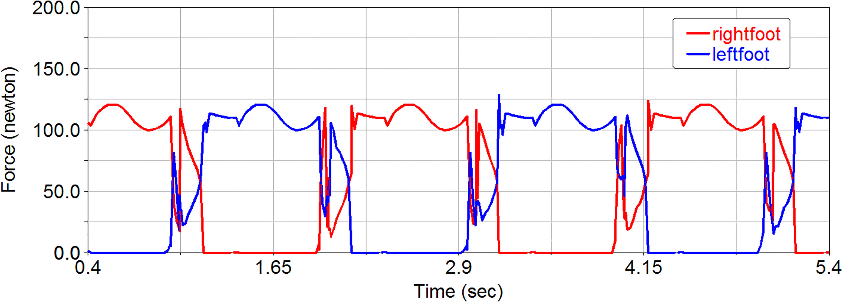
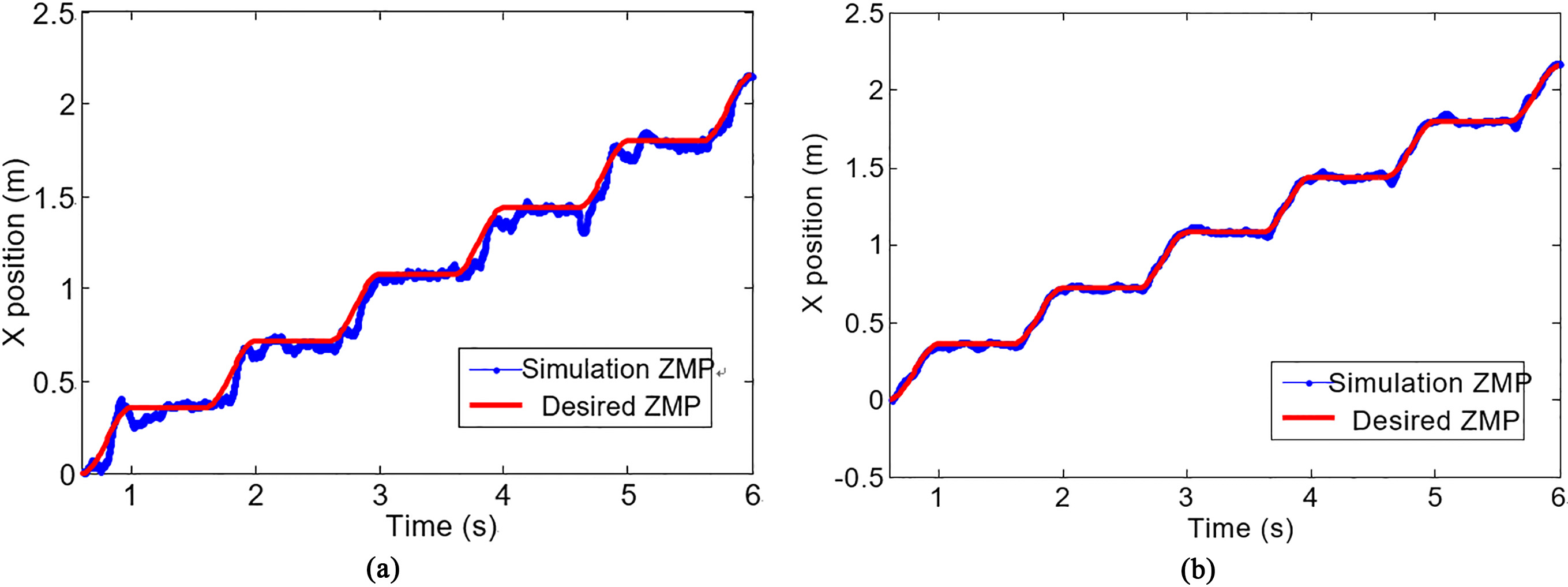
Figure 7 shows the desired and simulation ZMP trajectories. Obviously, the biped robot with variable stiffness ankle joint generates trajectories with a better ZMP curve than the biped robot with rigid ankle joint. It demonstrates that introducing the variable stiffness ankle joint controller can improve the stability of the biped robot walking.
Figure 7.
Desired and simulation ZMP trajectories. (a) Trajectories of biped robot with rigid ankle joint. (b) Trajectories of biped robot with variable ankle joint.
5.Experiments
5.1Experimental setup
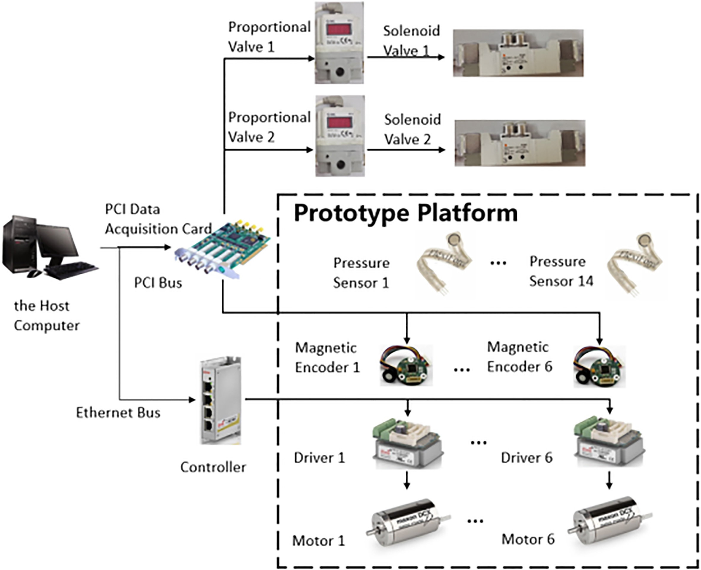
The proposed control scheme for walking control is evaluated on a biped robot system, as shown in Fig. 8. Its front width is 320 mm and hip joint is 612 mm from ground. The robot weighs 10.92 kg with the control system hardware. Control system of the robot is set as shown in Fig. 9. Fourteen pressure sensors (Flexiforce A201 Pressure Sensor) are installed in the robot foot to measure the force on foot-ground interface. Six drivers (Elmo-G-Whistle) are used to guarantee the servo-control of drive motor. Six magnetic encoders are installed in each joint to measure the rotary displacements which can be used to control the leg posture. The host computer controls the proportional valves and the solenoid valves via the data acquisition card to realize the control of ankle joints pneumatic units.
Figure 8.
Biped robot prototype platform.
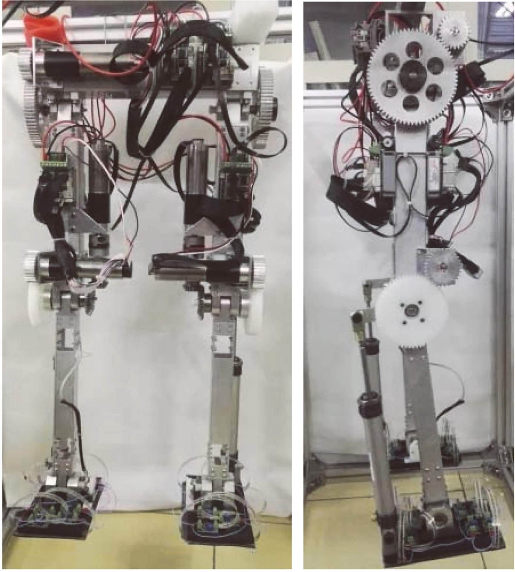
Figure 9.
Control system of the biped robot.
5.2Walking experiments
The experiments for verifications are set in two ways: the walking experiment with rigid ankle joints and the walking experiment with variable stiffness ankle joints. For the walking experiment with rigid ankle joint the pneumatic variable stiffness unit pressure is set as 0.6 MPa, which is approximately regarded as rigid joint. For the walking experiment with variable stiffness ankle joint the pneumatic variable stiffness unit is controlled as mentioned before to realize the variation stiffness of the ankle joint. As we can see from Figs 10 and 11, the biped robot can walk steadily in both conditions, in particular, achieve the rotation of ankle joints during the starting and landing of the gait, which validates the feasibility of the gait planning and control strategy.
Figure 10.
Walking experiment of biped robot with rigid ankle joint.
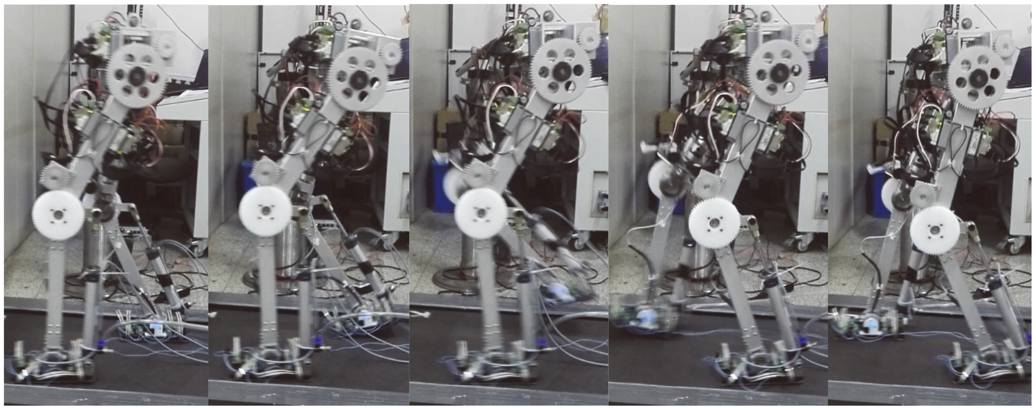
Figure 11.
Walking experiment of biped robot with variable stiffness ankle joint.
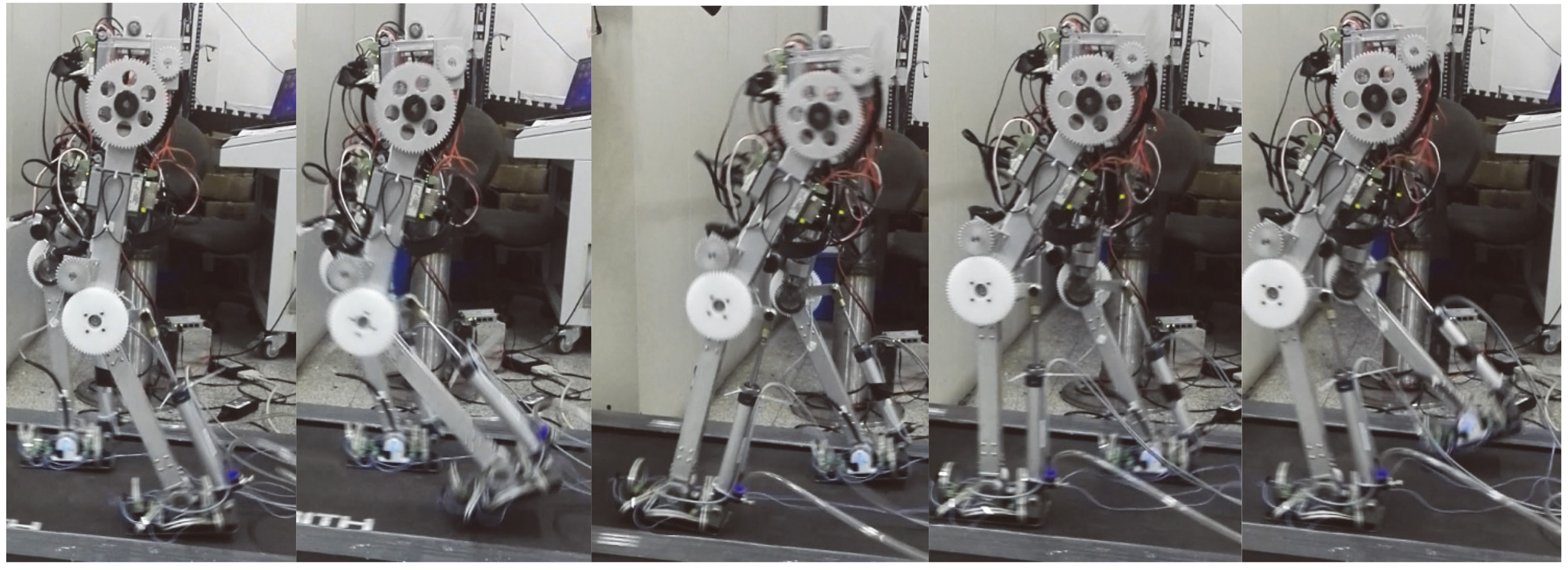
Figure 12.
Desired and real ZMP trajectories. (a) Trajectories of biped robot with rigid ankle joint. (b) Trajectories of biped robot with variable ankle joint.
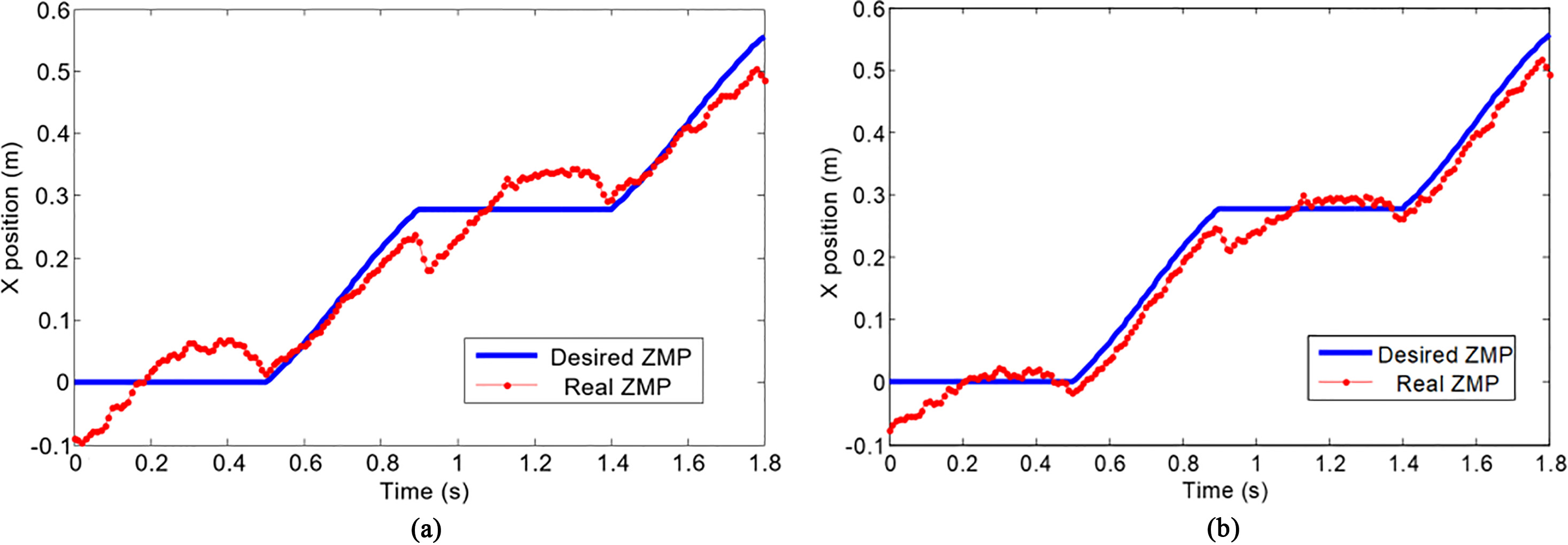
Figure 12 shows the desired and real ZMP trajectories. Obviously, the walking experiment with variable stiffness ankle joints generates trajectories with a better ZMP curve than the walking experiment with rigid ankle joints. The real ZMP curve with rigid ankle joints has abruptly changes in the opposite direction when the swing leg touches the ground, as depicted in Fig. 12a, indicating that the biped robot has suffered a large impact at this moment. At the end of the double support phase, the support foot is lifting off the ground and the real ZMP curve has abruptly changes in the opposite direction too, indicating that the robot has a tendency to fall over backwards. As shown in Fig. 12b, the real ZMP curve with variable stiffness ankle joints has better tracking the desired ZMP. Due to the compliance of the ankle joints, these oscillations are small when the feet touch and leave the ground. It demonstrates that the ankle joints with a variable stiffness control strategy reduce the foot-ground impact and improve the stability of the bipedal walking.
6.Conclusion
In this paper, variable stiffness ankle joint for designing, analyzing and controlling robotic systems has been investigated. A design is introduced that achieves the ankle joint variable stiffness by using a pneumatic unit, and a control architecture is proposed to make the biped robot walk stability. The simulated and experimental results have shown that the variable stiffness ankle joint and the controller in the biped robot system provide an improvement in foot-ground impact and walking stability of biped robot. We will study the effects of variable stiffness knee joints and variable stiffness hip joints on the walking stability of biped robots in future researches. And we will study the performance of the variable damping and the control strategies for best utilizing the variable dynamics of the biped robot.
Acknowledgments
The work was funded by the National Key R&D Program of China (no. 2018YFF01012304), and the National Natural Science Foundation of China (NSFC) (no. 51675116).
Conflict of interest
None to report.
References
[1] | Bihari TE, Wallister TM, Patterson MR, Controlling the adaptive suspension vehicle, IEEE Computer. (1989) ; 22: (6): 59-65. |
[2] | Garcia E, Arevalo JC, Muñoz G, Gonzalez-de-Santos P. Combining series elastic actuation and magneto-rheological damping for the control of agile locomotion. Robotics and Autonomous Systems. (2011) ; 59: : 827-839. |
[3] | Farley CT, González O. Leg stiffness and stride frequency in human running. Journal of Biomechanics. (1996) ; 29: : 181-186. |
[4] | Zelik KE, Huang TW, Adamczyk PG, et al. The role of series ankle elasticity in bipedal walking. Journal of Theoretical Biology. (2014) ; 346: (4): 75-85. |
[5] | Wang Q, Wei K, Wang L, et al. Modeling and stability analysis of human normal walking with implications for the evolution of the foot, IEEE Ras and Embs International Conference on Biomedical Robotics and Biomechatronics. IEEE, (2010) ; 479-484. |
[6] | Zhang Q, Teng L, Wang Y, et al. A Study of Flexible Energy-Saving Joint for Biped Robots Considering Sagittal Plane Motion, International Conference on Intelligent Robotics and Applications. Springer, Cham. (2015) : 333-344. |
[7] | Qiang Z, Xiao X, Yang W, et al. Compliant joint for biped robot considering energy consumption optimization, Journal of Central South University, (2015) . |
[8] | David RC, Maarten W, Diego T, et al. A Compliant 2-DoF Ankle-Foot System for a Biologically Inspired Humanoid Robot, IEEE-RAS International Conference on Humanoid Robots (Humanoids), (2015) ; 265-269. |
[9] | Hurst J. An Actuator with Mechanically Adjustable Series Compliance. Technical report, Carnegie Mellon University, (2004) . |
[10] | Jafari A, Tsagarakis N, Sardellitti I, Caldwell D. A New Actuator with Adjustable Stiffness Based on a Variable Ratio Lever Mechanism. IEEE/ASME Transactions on Mechatronics (2012) ; pp. 1-9. |
[11] | Martínez JL, Blanco J, Vallejo DG, Torres J, Fernández AG. AVASTT: A New Variable Stiffness Actuator with Torque Threshold. ROBOT 2013: First Iberian Robotics Conference. Springer, (2014) , pp. 573-583. |


