
Intelligent infusion controller with a physiological information feedback function
Abstract
BACKGROUND:
In hospitals, some problems still exist, such as transfusion reaction that cannot be dealt with in time, medical staff cannot observe the physiological information of the infusion patients in real time, and the infusion speed cannot be controlled smartly.
OBJECTIVE:
To address these problems, we propose a method for intelligent monitoring and designed a controller for dripping speed regulation.
METHODS:
A photoelectric sensor was used to obtain the heart rate (HR) information, and a PID parameter self-tuning controller based on the fuzzy control principle was developed to establish a multi-stage adaptive control method based on HR feedback. By controlling the rotation of the motor to drive the cam to control the drip rate smartly. Also, the infusion and physiological information are transmitted to the nurse station to monitor the possible transfusion reaction.
RESULTS:
The experiments show that the intelligent infusion controller can achieve HR signal detection with an average accuracy of over 94%, dripping speed detection and adjustment with an average accuracy of above 98% and adjustment time within 35 seconds.
CONCLUSION:
Our study proved that the intelligent infusion controller can control the infusion process intelligently and effectively, and has excellent reliability, small steady-state error and high practical value.
1.Introduction
Transfusion reaction is the general term of adverse reactions associated with infusion. Although the probability of clinical occurrence is not high, the mortality rate is high if it cannot be treated in time [1, 2]. On the contrary, if the transfusion reaction can be detected and handled in time, the harm of transfusion reaction to patients’ health and life safety can be reduced. At present, most hospitals use the combination of medical patrol and doctor’s recommendations to supervise the transfusion. The medical patrol will undoubtedly increase the workload of the medical staff. The way of doctor’s recommendations is to call the medical staff to carry out the corresponding infusion treatment after the patient’s subjective discomfort, but often the patient’s subjective feeling is lagging behind, and the best time for the infusion treatment is lost. Therefore, the development of intelligent infusion sets has become a way to solve clinical transfusion problems [3].
Intelligent infusion devices can improve the efficiency and flexibility of clinical administration and reduce the workload of medical care. However, the main problem of the current intelligent infusion devices is the low intelligence level. For example, some infusion devices can alarm the abnormal infusion speed, the end of the infusion or the emergence of bubbles in the infusion tube, but it is necessary to wait for the medical staff to carry out the infusion treatment, and the independent control of the infusion speed cannot be realized. The clinical example of Little Company of Mary Hospital in California shows that the use of the intelligent infusion device can greatly reduce the probability of common infusion problems; therefore, the intelligent and humanized infusion device has become the direction of further development [4, 5].
In order to further improve the intelligence of the infusion apparatus and establish the relationship between the infusion and the physiological state of the infusion, this study proposes an intelligent infusion controller with a physiological information feedback function. It can monitor the patient’s physiological information in real time. When the physiological information (heart rate) is abnormal, it can control the infusion speed (stop or slow down the infusion speed). Through the wireless network, the transfusion information can be transmitted to the nursing station, and the abnormal transfusion can be alarmed to minimize the harm caused by the infusion reaction to the patients. The controller has a good application prospect.
2.Intelligent infusion controller design
2.1Function and structure
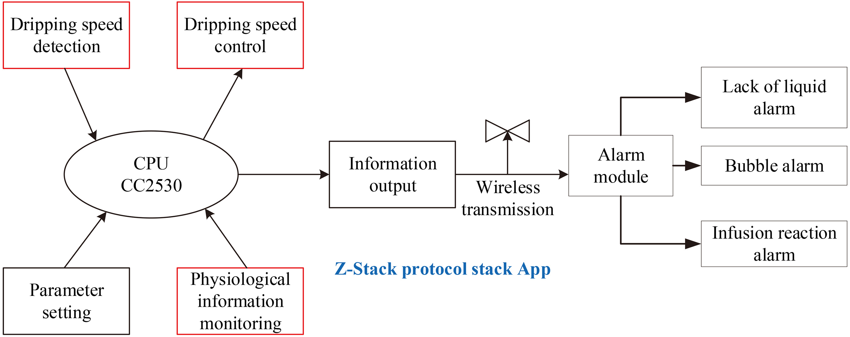
The common symptoms of transfusion reaction are closely related to the heart rate (HR) of the transfusion object. This study uses the HR signal as the feedback amount of biological information to realize the intelligent adjustment of the infusion speed. As shown in Fig. 1, the intelligent infusion device mainly includes HR detection module, drip rate detection-control module, alarm module, and user interface module.
Figure 1.
Schematic diagram of the function module of the intelligent infusion system.
The HR detection module uses the pulse sensor photoelectric volume method to detect the HR. This method of HR measurement is based on a photoelectric technology, that is, when the light of a certain wavelength is irradiated to the object, the amount of light absorption is proportional to the concentration of the object [6]. The absorption and reflection of light intensity of a fixed wavelength to the surface of the skin (such as the fingertips, toes, earlobe or wrist) of a fixed wavelength is used to measure the life characteristics of the human body. This HR test is commonly used in wearable devices, such as Apple’s Apple Watch, sports watches, and some bracelets.
Drop rate detection and control module, including intelligent control algorithm and mechanical control device, are the core of intelligent infusion device. The design method is described in detail in Sections 2.2 and 2.3.
The alarm module can prompt medical staff to deal with all kinds of abnormal transfusion situations in time. The alarm mode includes missing alarm, bubble alarm and suspected infusion reaction alarm. It checks the residual liquid volume by detecting the number of drops, and notifies the doctors and nurses to change the liquid in advance. Meanwhile, the infrared tube transmitting and receiving device is used at the lower end of the infusion tube for emergency treatment. At the same time, it can also be used to detect whether there is air entry in the infusion tube. If the detected HR information is significantly different from the initial HR of the infusion, the suspected infusion response alarm will be activated.
2.2Design of automatic control algorithm
2.2.1The phases of the control stage
Figure 2 shows the schematic diagram of the intelligent infusion system control stage, which includes three phases.
Figure 2.
Schematic diagram of the intelligent infusion system control stage.
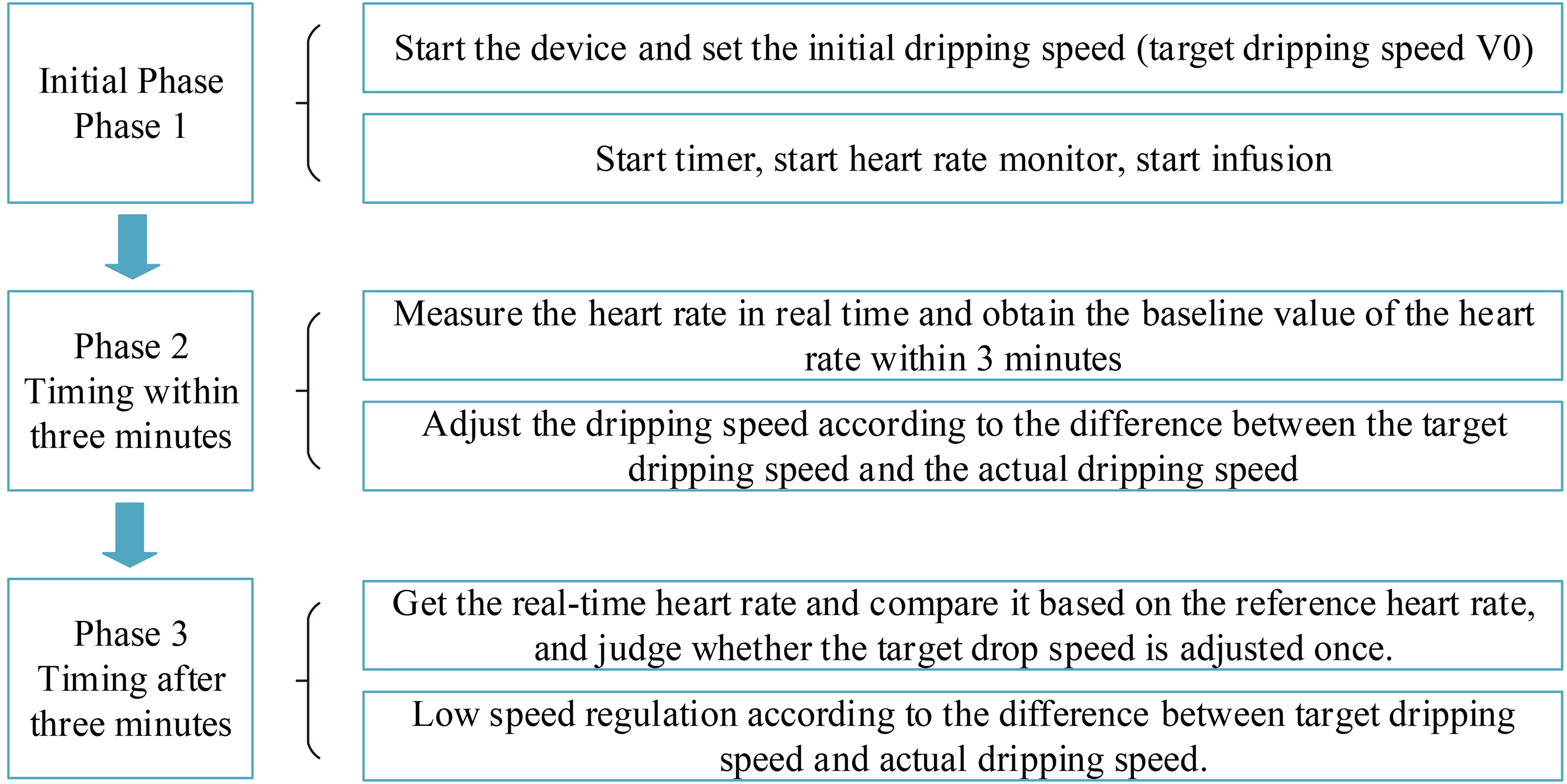
Phase 1 of the initialization control
Before the infusion begins, the doctor sets the initial drip rate (i.e. the target drip rate v0), then starts the infusion, starts the timer, and starts the HR test. In this phase of three minutes, the controller adjusts the motor to control the dripping speed according to the target dripping speed and the actual dripping speed difference. At this stage, an average of 3 minutes of HR can be obtained as a reference value for HR. After three minutes, the second stage is to set the target drip rate according to the difference between the real-time HR and its reference value. Further, the controller controls the dripping speed according to the target dripping speed and the actual dripping speed difference.
Phase 2 of the control process
As shown in Fig. 3, in this phase, the controller adjusts the motor’s rotation speed according to the difference between the target dropping speed and the actual dropping speed for the dripping speed control. Meanwhile, the human HR
In the formula,
Figure 3.
The first 3 minutes control block diagram of the intelligent infusion system.
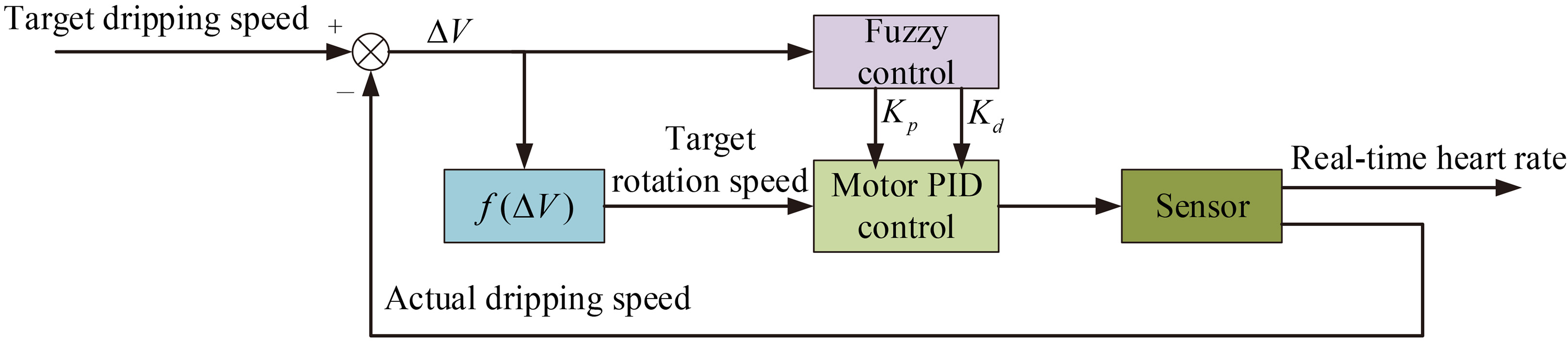
Figure 4.
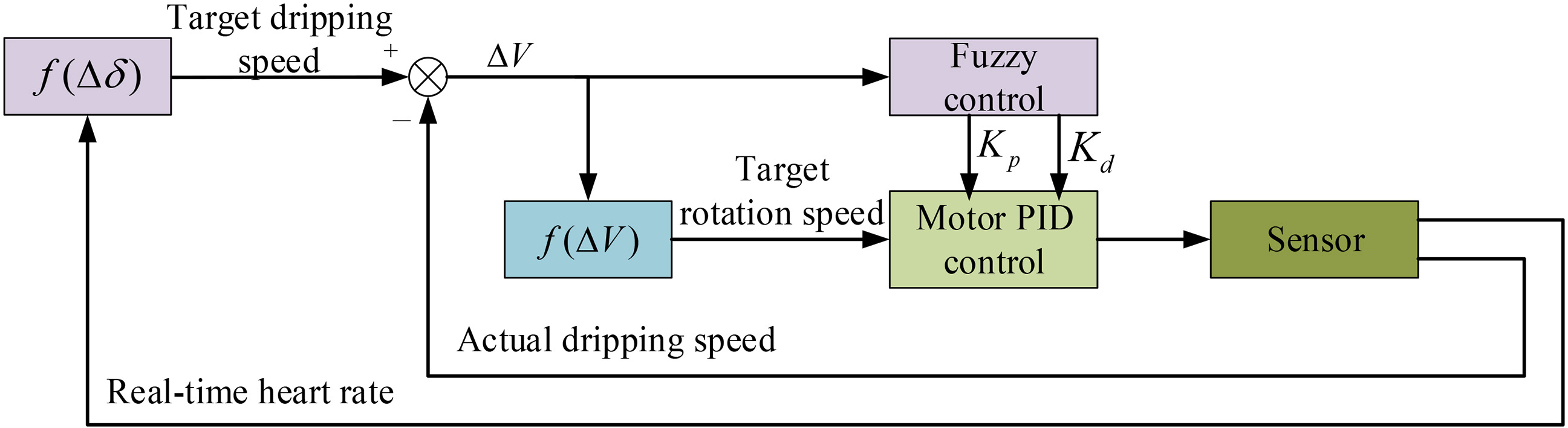
Control block diagram of the intelligent infusion system after 3 minutes.
Phase 3 of the control process
After 3 minutes, the real-time HR monitored by the sensor determines the target drip rate through the function
As can be seen from Fig. 4, after 3 minutes of infusion, the real-time HR monitored by the sensor determines the target dripping speed. In this figure,
The function
According to the above formula, when the change of HR is less than 15% of the baseline HR, the infusion dripping speed is the same as the baseline dripping speed
2.2.2Control algorithm for dripping speed adjustment
The target rotation speed of the motor is determined by the difference between the target dripping speed and the actual dripping speed, and the control coefficient (
In Fig. 4,
Therefore, we need to determine the different motor control parameters based on the size of the drop rate difference. In view of that PID control problem of self-setting parameters in the system, a PID parameter-self-adjusting controller based on fuzzy control principle is adopted. In contrast to traditional PID control, the fuzzy PID control makes full use of the expert’s experience to construct the fuzzy rules and adjust the parameters of the controller, which can fully exert the control action of the controller, so that the whole system can be controlled better. The control block diagram is shown in Fig. 5.
Figure 5.
Fuzzy PID control schematics.
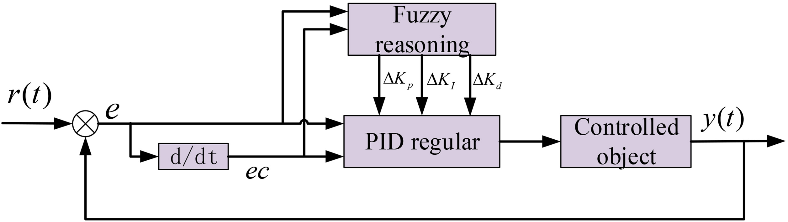
It can be seen from the practical operation experience of a large number of control engineering experts that the nonlinear relationship between the three parameters of the PID controller and the system deviation
1. When
2. When
3. When
According to the actual situation of the system, the adjustment quantities of three parameters, deviation and deviation rate are divided into continuous fuzzy sets in their theoretical domain, which are generally seven: NB (negative big), NM (negative middle), NS (negative small), ZO (zero), PS (positive small), PM (positive middle) and PB (positive big) [8, 9]. According to the experience summarized above, the fuzzy rules governing three parameters of the PID controller are formulated, such as:
Table 1
Fuzzy rules governing
| [height=0.8cm,width=2.4cm] | NB | NM | NS | ZO | PS | PM | PB |
|---|---|---|---|---|---|---|---|
| NB | PB | PB | PM | PM | PS | ZO | ZO |
| NM | PB | PB | PM | PS | PS | ZO | NS |
| NS | PM | PM | PM | PS | ZO | NS | NS |
| ZO | PM | PM | PS | ZO | NS | NM | NM |
| PS | PS | PS | ZO | NS | NS | NM | NM |
| PM | PS | ZO | NS | NM | NM | NM | NB |
| PB | ZO | ZO | NM | NM | NM | NB | NB |
Table 2
Fuzzy rules governing
| [height=0.8cm,width=2.4cm] | NB | NM | NS | ZO | PS | PM | PB |
|---|---|---|---|---|---|---|---|
| NB | PB | PB | PB | NB | NB | NM | NS |
| NM | PB | PB | PM | NM | ZO | PS | PM |
| NS | PB | PM | PM | NS | PM | PB | PB |
| ZO | ZO | ZO | ZO | ZO | ZO | ZO | ZO |
| PS | PB | PB | PM | NS | PM | PM | PB |
| PM | PM | PS | ZO | NM | PM | PB | PB |
| PB | NS | NM | NB | NB | PB | PB | PB |
Specific rules of the fuzzy PID controller are shown in Tables 1 and 2. According to the specific conditions of
2.3Mechanical design of the controller
The mechanical part of the infusion controller is the carrier to realize the infusion control, and the main structures include a Murphy’s burette slot, a drip-speed control unit, a drip-speed sensor and a bubble sensor mounting holes. The drip-speed control unit consists of a rotating CAM and baffle, through which the drip tube at the back of the Murphy’s burette is passed. The CAM controlled by the motor can adjust the clamping degree of the drip tube through rotation, so as to control the drip speed. The mechanical structure and physical objects are shown in Fig. 6.
Figure 6.
Mechanical structure and physical objects of the infusion controller.
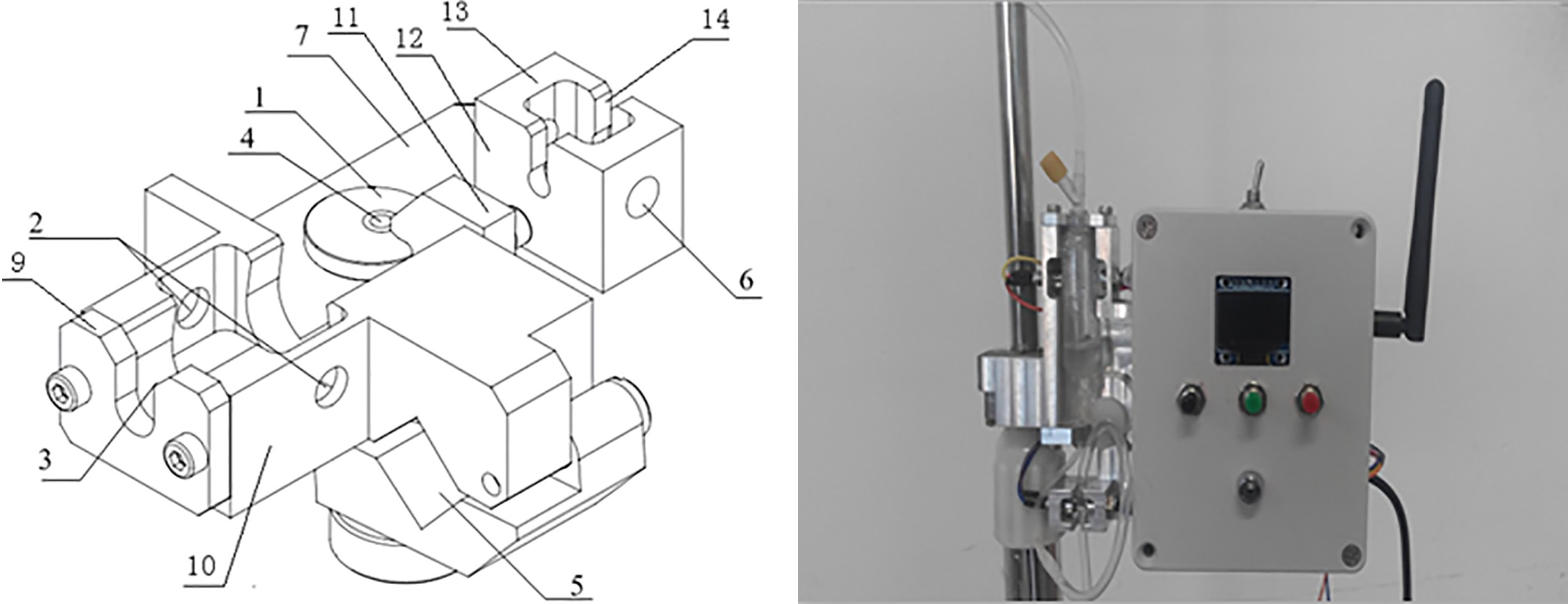
Figure 7.
The remote wireless infusion monitoring system networking framework.
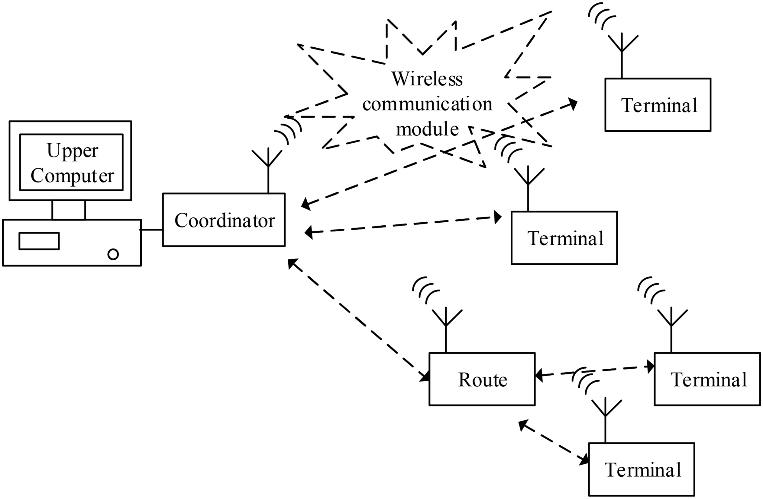
2.4Wireless network system for infusion monitoring [10, 11, 12, 13]
Based on the design of the intelligent infusion controller with a physiological information feedback function, it can be further extended to a wireless infusion monitoring system, and its networking framework is shown in Fig. 7. It is mainly composed of the upper computer, coordinator, routes and terminals. The upper computer receives and displays the patient’s infusion physiological information and infusion speed and other information transmitted by the coordinator in real time, and can also set the patient’s infusion speed through the keyboard, and alarm if there is any abnormality. The coordinator transmits the patient’s infusion physiological information and infusion speed and other information sent by the terminals (or routers) through the wireless network to the upper computer, and sends the instructions of the upper computer to the terminals through the wireless network [14, 15]. The terminal should have the following basic modules: the infusion speed detection module, the infusion speed control module, the patient’s physiological information acquisition module, the keypad module, the display module, the wireless networking module and the alarm module. The route has the functions of the terminal, and can forward the terminal information to the coordinator, which extends the network coverage.
3.Results
3.1HR detection
First, the HR algorithm is validated by ECG signal generator. The HR output range is set 30 to 300. Through 20 sets of data tests, the recognition accuracy of our HR algorithm is 98%. In addition, 30 volunteers (aged 10–65 years) were selected for further human experiment verification, and the HR detection module was compared with Colin n1bp-88s monitor (Colin Corporation, Japan). The results show that the detection accuracy of HR detection module is over 94%, which can provide a basis for the judgment of infusion response.
3.2Dripping speed detection
In order to evaluate the accuracy of the sensor in measuring the dripping speed, the sensor dripping speed measurement was compared with the manual measurement, and the stopwatch was used to time the measurement of the manual drop rate. In 30 tests, the dripping speed was set 30 to 150, and the average accuracy of the sensor dripping speed measurement is over 98%.
3.3Dripping speed control
3.3.1Comparison of the target dripping speed (setting dripping speed) with actual dripping speed
After manually setting the dripping speed and then waiting for the end of the system speed regulation, the dripping speed measured by the sensor is compared with the set dripping speed. There results after several measurements are shown in Table 3. According to the test data, the intelligent infusion system can accurately control the dropping speed of the infusion system to reach the set target value in five tests. Combined with the experimental results of the sensor dropping speed detection (the average coincidence rate of dropping speed
Table 3
Records of dripping speed setting value and actual value
| Test number | 1 | 2 | 3 | 4 | 5 |
| Setting dripping speed | 40 | 60 | 80 | 100 | 120 |
| Dripping speed measured by sensor | 40 | 60 | 80 | 100 | 120 |
| Error | 0 | 0 | 0 | 0 | 0 |
Table 4
Time records of adjusting the dripping speed
| Initial dripping speed (drops/min) | Target dripping speed (drops/min) | Adjustment time (sec) | Initial dripping speed (drops/min) | Target dripping speed (drops/min) | Adjustment time (sec) |
| 80 | 120 | 21 | 40 | 80 | 21 |
| 80 | 100 | 18 | 40 | 100 | 23 |
| 80 | 60 | 15 | 40 | 120 | 30 |
| 80 | 40 | 19 | 20 | 40 | 38 |
| 80 | 20 | 32 | 20 | 60 | 25 |
| 40 | 20 | 28 | 20 | 80 | 30 |
| 40 | 60 | 19 | 20 | 100 | 31 |
3.3.2Adjustment time to achieve target dripping speed
The intelligent infusion system has a certain initial dripping speed. After manually setting the dripping speed, the intelligent infusion system will automatically adjust the speed, and wait for the sensor to stabilize to the target dripping speed and analyze the adjustment time. The results after several measurements are shown in Table 4. The test shows that the intelligent infusion system can quickly and accurately control the dropping speed of the infusion system to reach the set target value. When the target dropping speed is the same, the less the absolute error between the initial dropping speed and the target dropping speed is, the less adjusting time the intelligent infusion system needs. When the initial dropping speed is the same, the less the absolute error between the initial dropping speed and the target dropping speed is, the less adjusting time the intelligent infusion system needs.
4.Discussion and conclusion
Intravenous infusion is the most common medical method in clinical treatment. In view of the problems of inaccurate control of traditional infusion drip rate, inappropriate detection and treatment of infusion reaction, and inability of real-time monitoring of physiological information of infusion patients, this design proposes a monitoring and control method of infusion drip rate with physiological information feedback, which can be used in 35 seconds. The accuracy rate of the dripping speed is over 98%, and the accuracy of the HR signal detection reaches 94%. The fuzzy PID compound controller is used to control the dropping speed of the infusion, which effectively solves the nonlinear relationship between the dropping speed and the height of the liquid and improves the steady-state accuracy of the system.
The intelligent infusion control system designed in this paper realizes the centralized monitoring of patients’ infusion information and physiological information. The functions of dripping speed control and HR detection can fully meet the basic requirements of general large and medium-sized infusion rooms or hospitals. The sound and light alarm function can prompt medical staff to deal with patients’ lack of fluid and suspected infusion reaction situation in time. Experiments show that the intelligent infusion control system has stable performance, reliability, small steady-state error and high practical value.
Acknowledgments
This work was supported by the ‘111 Project’ (No. B13044) and ‘Major Program’ (No. ALJ17J001).
Conflict of interest
None to report.
References
[1] | Xiao Y, Ren CL, Miao LL. Efficacy and Safety of Cetuximab in the Adjuvant Chemotherapy Treatment of Advanced Non-small Cell Lung Cancer: a Meta-analysis. China Pharsmacy. (2015) . |
[2] | Pabinger I, Tiede A, Kalina U, et al. Impact of infusion speed on the safety and effectiveness of prothrombin complex concentrate: A prospective clinical trial of emergency anticoagulation reversal. Annals of Hematology. (2010) ; 89: (3): 309–316. doi: 10.1007/s00277-009-0830-7. |
[3] | Zhang YY, Zhou YF. The effect of implementing an intelligent intravenous infusion system on improving safety. Chinese Nursing Management. (2016) ; 16: (10): 1412–1415. |
[4] | Arney DE, Jetley R, Jones P, et al. Generic Infusion Pump Hazard Analysis and Safety Requirements Version 1.0. U.S.A: University of Pennsylvania. (2008) : MS-CIS-08-31. |
[5] | Lin WC, Villez KRE, Garcia HE. Experimental validation of a resilient monitoring and control system. Journal of Process Control. (2014) ; 24: (5): 621–639. doi: 10.1016/j.jprocont.2014.03.006. |
[6] | Zuo DQ, Qian LX, Yang TE, Cui XJ, Luo Q. Coupling leveling control based on fuzzy PID for synchronous loading system of load-bearing test bed. Chinese Journal of Electronics. (2017) ; 26: (6): 1206–1212. |
[7] | Liu FC, Liang LH, Gao JJ. Fuzzy PID control of space manipulator for both ground alignment and space applications. International Journal of Automation and Computing. (2014) ; 11: (4): 353–360. doi: 10.1007/s11633-014-0800-y. |
[8] | Kumar V, Mittal AP, Singh R. Stability analysis of parallel fuzzy P + fuzzy I + fuzzy D control systems. International Journal of Automation and Computing. (2013) ; 10: (2): 91–98. doi: 10.1007/s11633-013-0701-5. |
[9] | Liu WH, Xie Z. Design and simulation test of advanced secondary cooling control system of continuous casting based on fuzzy self-adaptive PID. Journal of Iron and Steel Research (International). (2011) ; 18: (1): 26–30. doi: 10.1016/s1006-706x(11)60006-x. |
[10] | Dong SL. Intelligent infusion monitoring system design based on service and experience. Packaging Engineering. (2016) ; 37: (18): 125–128. |
[11] | Wang YW, Lu J, Zhang CC, Chen H. Design of intelligent infusion monitoring system based on wireless sensor network. Measurement and Control Technology. (2015) ; 34: (11): 64–66. |
[12] | Wen X. Design of Medical Infusion Monitor and Protection System Based on Wireless Communication Technology. In International Symposium on Intelligent Information Technology Application. (2008) : pp. 755–759. doi: 10.1109/iita.2008.47. |
[13] | Xu GX, Guo L, Lu W. Design and implementation of intelligent infusion monitoring system. Laser Journal. (2014) ; 35: (9): 119–121. |
[14] | Xu D, Feng P, Ren S, et al. Design of Remote Medical Monitoring System Based on ZigBee Technology. In IEEE Fifth International Conference on Big Data and Cloud Computing. (2015) : pp. 199–202. doi: 10.1109/bdcloud.2015.21. |
[15] | Chen YJ, Liu PX, Jin PF, et al. The design of elderly apartment infusion monitoring system based on wireless module APC220. Advanced Materials Research. (2014) ; 926-930, 470-473. doi: 10.4028/www.scientific.net/amr.926-930.470. |


