
Design of a dual-coil type electromagnetic actuator for implantable bone conduction hearing devices
Abstract
BACKGROUND:
This paper describes the design and implementation of a dual-coil type electromagnetic actuator for implantable bone conduction hearing devices.
OBJECTIVE:
The structure of the proposed actuator was designed to generate maximum Lorentz force via the dual-coil method with a closed magnetic circuit. To satisfy the indications required by implantable bone conduction hearing devices, high output was generated within a specific frequency range using a vibrational membrane with a cantilever.
METHODS:
The structure of the membrane consists of a fixed ring, a circular plate, and two cantilevers connected symmetrically. Variable elements of the vibrational membrane affecting the actuator frequency characteristics were analyzed through mathematical modeling and finite element analysis, based on the analysis used to derive the optimum structure of the vibrational membrane. The components of the actuator were fabricated through chemical etching and computer numerical control process, and the bone conduction actuator was fabricated through the precision assembly process.
RESULTS:
The output characteristics of the implemented actuator were measured using a laser Doppler vibrometer. As a result of measurement, the proposed actuator generated mechanical resonance at 1.2 kHz.
CONCLUSIONS:
By comparing the measured results with the finite element analysis results, we confirmed the validity of the proposed actuator design.
1.Introduction
With the development of medical technology and the generalization of medical services, the average human life span has increased to over 80 years. As a result, hearing loss, which is a representative disease of the aging society, is steadily increasing [1, 2]. In addition, the increase in use of various multimedia devices is leading to an increase in the overall prevalence of hearing loss, which is emerging as a social issue. Various studies have examined the treatment and rehabilitation of hearing loss diseases [3, 4].
In general, medical devices for hearing loss rehabilitation include air conduction hearing aids with sound pressure output, cochlear implants with electrical output, and implantable middle ear implants with vibrational output [5, 6, 7]. Air conduction hearing aids are problematic in terms of closure of the external ear canal and howling effects, and are applicable to mild hearing loss only. However, since this hearing aid does not require surgery, it is the first hearing rehabilitation device that many hearing-impaired people use [8]. Cochlear implants are the only auditory rehabilitation devices applicable to severe hearing loss patients. Cochlear implant uses a surgically implanted neuroprosthetic device (electrode arrays) to stimulate the cochlea nerve to transmit sound. Therefore, cochlear implants require complex surgery and the target application is different to that of other hearing rehabilitation devices [9]. In general, middle-ear implants use a method of attaching a small actuator to the ossicles to transmit a vibrational signal to the cochlear. Therefore, middle-ear implants can generate higher output than air conduction hearing aids and, because vibration is used as an output medium, the original sound can be reproduced without acoustic feedback, which is faithful to the original function of the hearing aid. However, middle-ear implants such as cochlear implants require surgery [10].
Recently, implantable bone conduction hearing devices, which have the advantages of middle-ear implants and are surgically easy to implant, have been actively studied [11, 12]. Unlike conventional middle ear implants that transmit the output to the ossicles using a small actuator, an actuator with a relatively large and high vibrational force is implanted into the mastoid to deliver voice signals through bone conduction [13]. The output device of the bone conduction hearing aid should have a very high output because the voice signal transmitted along the skull is mostly lost in the propagation process. Recent studies have focused on improving the output of bone conduction actuators, but high frequency loss due to the bone conduction path cannot be avoided even with high output [14]. Considering that most hearing-impaired people have sensorineural hearing loss, research to improve the high frequency output characteristics of the hearing aid output device is inevitably a task to be solved.
In this paper, an electromagnetic actuator with a new structure for use in implantable bone conduction hearing devices has been proposed. The proposed actuator is designed to have maximum electromagnetic force by using a dual-coil method and magnetic circuit. Also, mechanical resonance was generated using a vibrational membrane with a cantilever structure so that the actuator occur a high vibrational displacement in a specific frequency region. The vibrational characteristics of the proposed actuator are decided by the vibrational membrane of the cantilever structure and the geometrical shape of the vibrational membrane was derived through mathematical modeling and the finite element method. Using the analysis results, an actuator was fabricated, and the no-load condition vibration characteristics of the actuator were measured by using a laser Doppler vibrometer (LDV). The validity of the actuator design was verified by comparing the measured results with the finite element analysis results.
2.Design of the dual-coil electromagnetic actuator
The implantable bone conduction hearing aid consists of an external system with a microphone for collecting external sound signals, an implant system with a signal processing device, and an actuator for outputting mechanical vibration, as shown in Fig. 1. The sound signal collected by the microphone is transformed into an electrical signal and is appropriately corrected through the signal processing device according to the hearing loss level of the hearing-impaired person. Then, the processed electrical signal is converted into a vibrational signal by the actuator, which is an output device, and directly transmitted to the cochlea of the inner ear through the bone. Through this process, the cerebrum recognizes the sound signals.
![The components of the implantable bone conduction hearing aid [15].](https://content.iospress.com:443/media/thc/2019/27-S1/thc-27-S1-thc199039/thc-27-thc199039-g001.jpg)
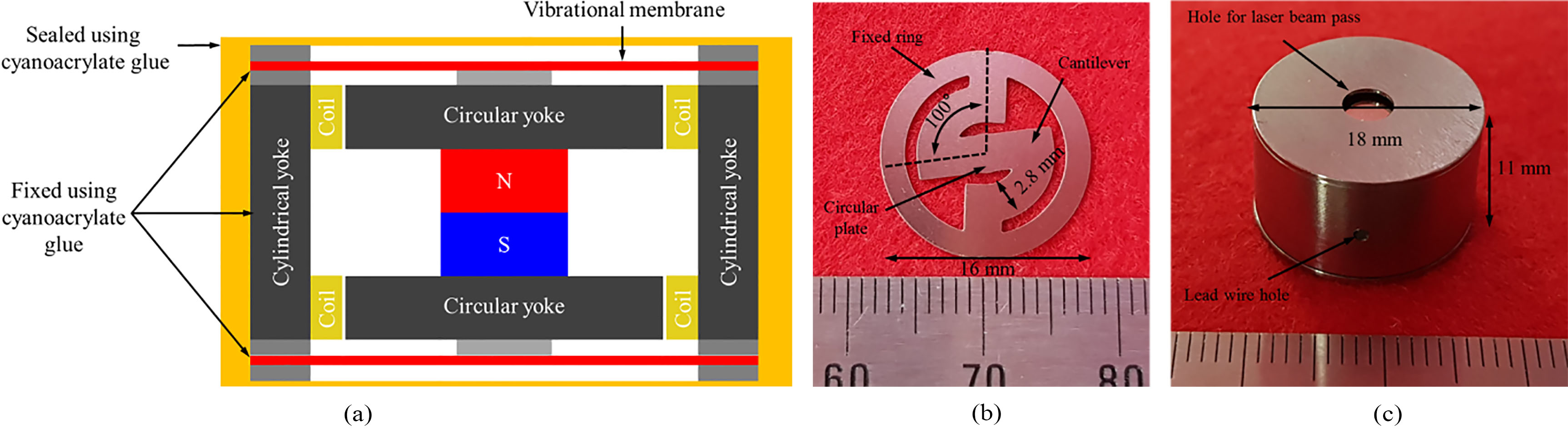
In the case of middle-ear implant actuators, the limited space in the middle-ear cavity limits the size of actuator that can be implanted. On the other hand, since the implantable bone conduction actuator is implanted in the mastoid, a larger size actuator can be used, as compared to the middle-ear implant actuators [16, 17, 18]. Based on the computed tomography image of the cranium [16], the dimension of the actuator was set at 18 mm in dia. and 11 mm in height. The exploded view of the proposed bone conduction actuator is shown in Fig. 2. The proposed actuator is composed of a titanium housing, a dual-coil (top and bottom) and permanent magnet for generating electromagnetic force, a vibrational membrane (top and bottom) with a cantilever structure for generating mechanical resonance, a magnetic circuit yoke for maximizing the magnetic density, a ring support for securing gap between the vibrational membrane and the components (such as the housing and yoke), and a metal tip for connecting the vibrational membrane and the permanent magnet.
Figure 2.
Part drawing of the proposed bone conduction actuator.
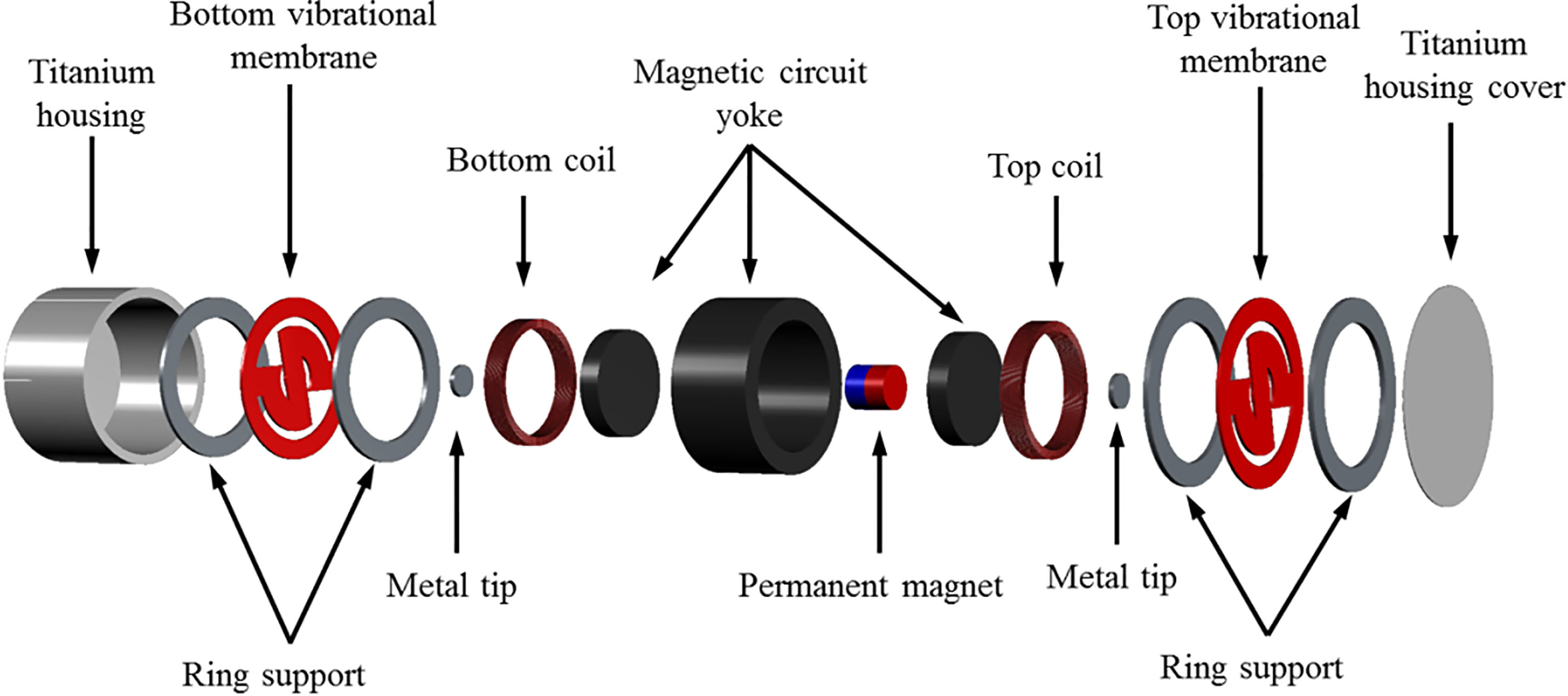
Figure 3.
Proposed vibrational membrane structure.
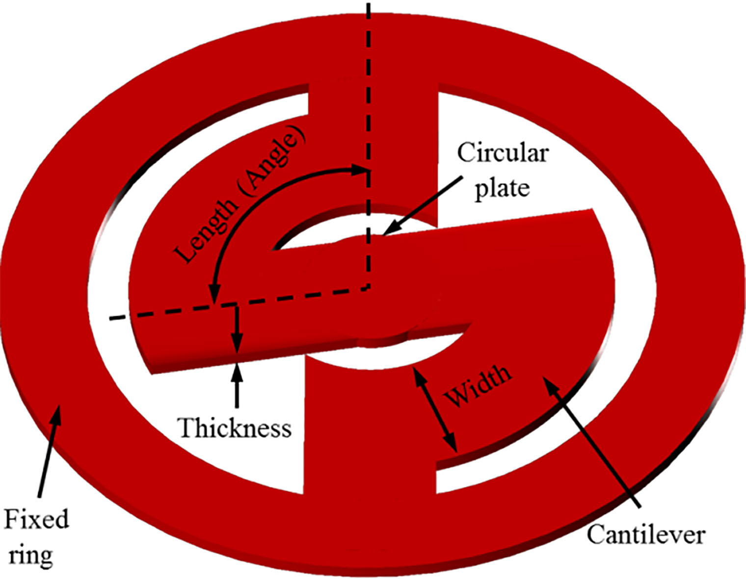
The shape of the proposed vibrational membrane consists of a fixed ring, a circular plate, and two cantilevers connected symmetrically, as shown in Fig. 3. The frequency characteristics of the vibrational membrane are determined by the number, width, thickness, and length (angle) of the cantilevers, which are variable elements. If the variable elements are appropriately adjusted, the mechanical resonance frequency required by the bone conduction actuator can be obtained. The frequency response characteristics of the vibrational membrane are determined by the stiffness coefficient. The stiffness coefficient of two vibrational membranes (top and bottom) connected in parallel can be calculated by Eq. (1) [19, 20].
(1)
Here,
The bone conduction actuator can be represented by a two degree of freedom system composed of a spring (top and bottom vibrational membrane) and mass (magnet and yoke). The mechanical resonance frequency of the actuator can be theoretically calculated by the stiffness coefficient of the vibrational membrane and the mass applied to the vibrational membrane as in Eq. (2).
(2)
Here,
In other words, the mechanical resonance frequency of the actuator can be derived from Eqs (1) and (2). As shown in Eq. (1), the component with the greatest influence on the determination of the frequency characteristics of the actuator is the length (angle) and thickness of the cantilever. The mechanical resonance frequency of the actuator can be derived through mathematical analysis. However, finite element analysis (FEA) is needed to analyze the complex correlation characteristics between the electromagnetic force generated by the magnets, coils and components of the actuator. Therefore, electromagnetic analysis and mechanical vibration analysis were performed using FEA program (COMSOL Multiphysics 5.4; COMSOL Inc., Stockholm, Sweden) to derive the optimum vibrational characteristics of the bone conduction actuator.
Implantable bone conduction hearing devices can be used for mixed and sensorineural hearing loss, but they are used primarily for conductive hearing loss accompanied by aural atresia [21]. According to the audiogram of a conductive hearing loss case, the hearing level of the low-frequency band is lowered, so hearing compensation is required in this band [22]. Therefore, the frequency output characteristic of the bone conduction hearing aid should compensate the low-frequency band by generating mechanical resonance near 1.2 kHz. Therefore, the output characteristic of the proposed bone conduction actuator was designed to generate mechanical resonance at 1.2 kHz.
Since the output characteristics of the bone conduction actuator are determined by the vibrational membrane with the cantilever shape, the FEA was performed on the vibrational membrane shape and the actuator components to produce an output characteristic suitable for conductive hearing loss applications. First, to obtain the maximum Lorenz force generated by the permanent magnet and the dual-coil, electromagnetic analysis was performed using a two-dimensional axisymmetric model as shown in Fig. 4a. Here, the mesh of the model is composed of 421 boundary elements and 6,825 domain elements. In the modeling, a permanent magnet (NdFeB) with a dia. of 4 mm and a height of 4 mm was placed at the center. Then, metal yokes were arranged at the top, bottom, and outside of the coil of the magnet to construct a magnetic circuit. The dual-coils were of the same size at the top and bottom. To maximize the Lorentz force generated by the magnet and the dual-coil, the currents flowing through the coils were set to be opposite to each other. Each coil has an outer dia. of 12.2 mm, an inner dia. of 10.2 mm, a height of 2 mm, a thickness of 55
Figure 4.
(a) Two-dimensional axisymmetric model for the electromagnetic analysis and (b) electromagnetic analysis results.
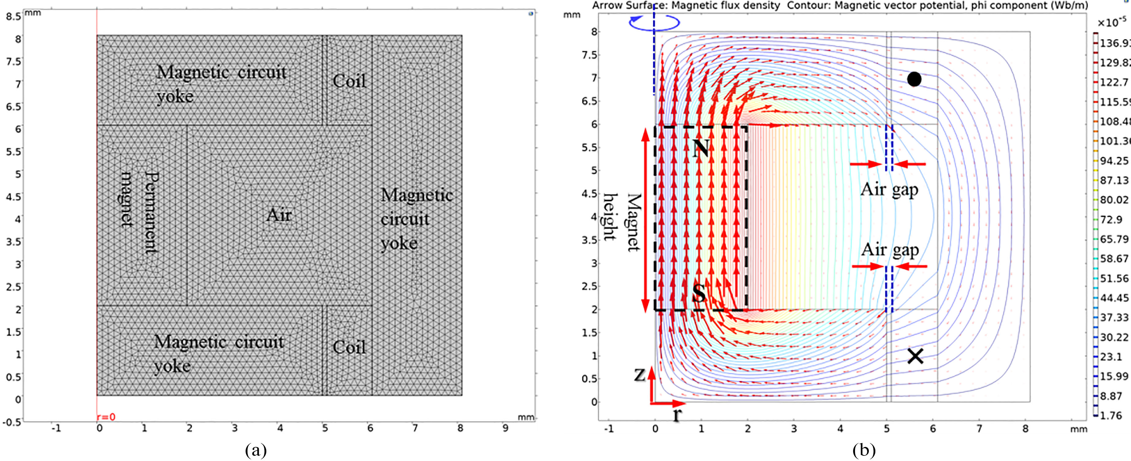
Figure 5.
(a) Three-dimensional model for mechanical vibration analysis, (b) mechanical vibration analysis results and (c) vibrational output graph of the proposed actuator according to the cantilever’ angle.
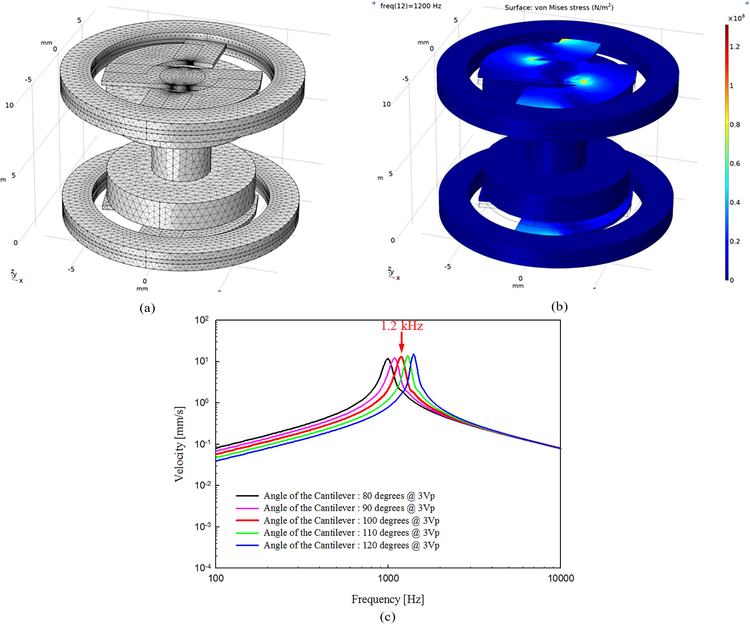
In order to determine the optimal vibration characteristics of the actuator, mechanical vibration analysis was carried out toward shape of the vibrational membrane. Considering the ease of fabrication of the vibrational membrane, the cantilever’ thickness and width were fixed at 0.3 mm and 2.8 mm, respectively. In the modeling of mechanical vibration analysis, only the permanent magnet, vibrational membrane, ring support, and two circular metal yokes were represented. The reason for this representation is that the cylindrical metal yoke, the coil and the housing are completely fixed to the skull, and do not affect the vibration characteristics of the vibrational membrane. The expressed components in the modeling were configured using the solid mechanics routine of the structure mechanics sub-module, and then combined by the “form union” command. The fixed ring of the top and bottom vibrational membrane for coupling with the housing was fixed using a defined “fixed constraint”. The prescribed displacements of the permanent magnet, circular metal yoke and cantilever of the vibrational membrane were set to “free/free”. The force of the boundary load applied to the permanent magnet during mechanical vibration analysis was that which had been calculated previously (1440.5 mN). The total load applied to the permanent magnet and circular metal yoke was 3.3 g. Figure 5a shows the three-dimensional model used to perform the mechanical vibration analysis. The mesh of the three-dimensional model consisted of 6,786 edge elements, 61,963 boundary elements, and 236,693 domain elements using a defined “free tetrahedral”. The vibrational membrane (stainless steel 316, SUS316), ring support (SUS316), and two circular metal yokes (stainless steel 304, SUS304) used in the modal analysis had the following characteristics: vibrational membrane’ density, 8070 kg/m
Using the analytical model, the angle of the cantilever was simulated in units of 10
3.Implementation of the bone conduction actuator
Based on the results of the FEA, the components of the bone conduction actuator were fabricated as follows. The vibrational membrane (dia.: 16 mm, angle: 100
Figure 6.
(a) Layout drawing of the actuator, (b) fabricated vibrational membrane of the cantilever structure and (c) implemented bone conduction actuator.
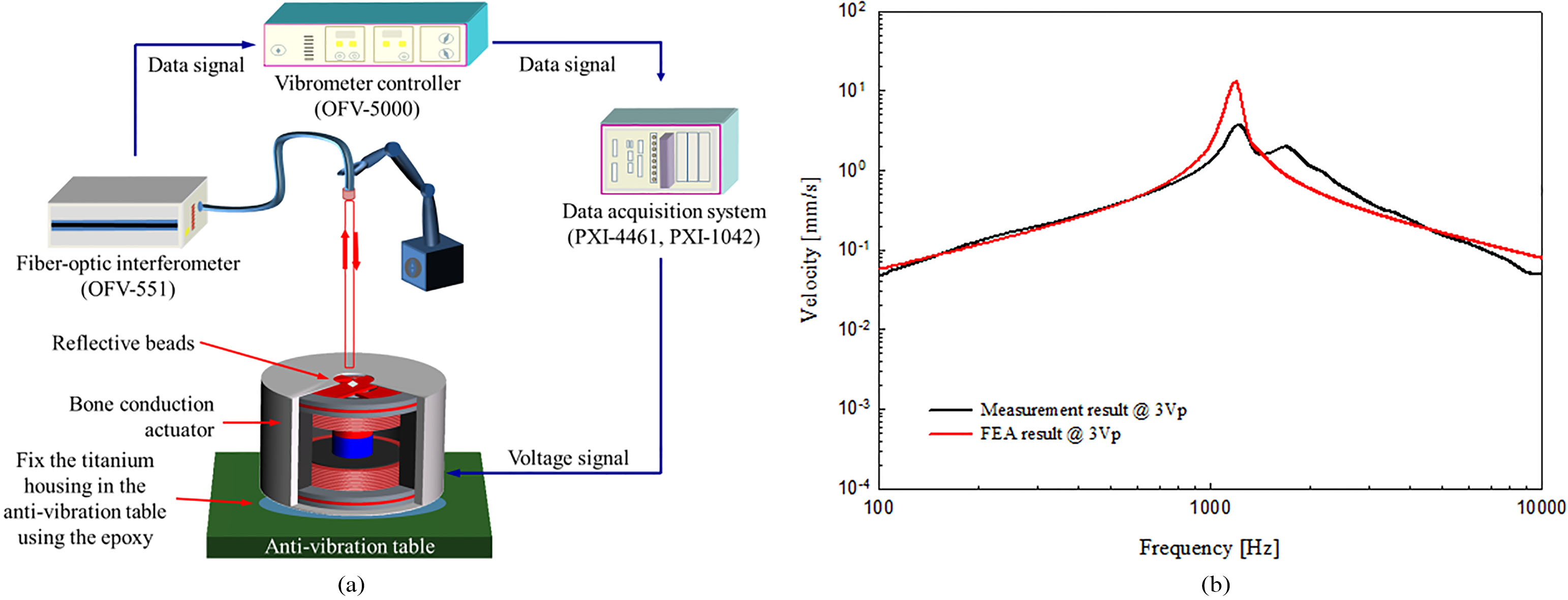
To verify the output characteristics of the manufactured bone conduction actuator, the frequency response characteristic was measured under no-load conditions. The experimental environment setup for vibration measurement is shown in Fig. 7a. All measurements were performed using a data acquisition system of FFT-based (number of FFT: 8,192, sampling rates: 96 kHz, DAQ; NI PXI-1042 and NI PXI-4461; National Instruments Co., USA). The measurement system generates a sinusoidal signal for driving the bone conduction actuator and at the same time measures the vibrational characteristics using the LDV (OFV-5000 (controller) and OFV-551 (laser); Polytec GmbH, Germany). The titanium housing of the actuator was completely fixed to the anti-vibration table using epoxy. To measure the vibration characteristics using the LDV, a 4 mm dia. hole was drilled through the top of the titanium housing to allow the laser beam to pass through it, and reflective beads were attached to the center of the top vibrational membrane. The sine wave signal corresponding to 3 Vp was applied to the actuator and the frequency response characteristic was measured; the result is shown in Fig. 7b. In Fig. 7b, the black solid line is the frequency output characteristic of the bone conduction actuator measured by LDV, and the solid red line is the result of the mechanical vibration analysis. Comparing the measured and analyzed results, the two results have generally similar frequency characteristics. Therefore, the actuator was implemented according to the theoretical design.
Figure 7.
(a) Vibration measurement system and (b) comparison of output characteristics between the fabricated actuator and FEA model.
4.Discussion and conclusions
In this study, we implemented a novel electromagnetic actuator using a dual-coil and magnetic circuit for implantable bone conduction hearing devices. To satisfy the function as a bone conduction actuator for treating conductive hearing loss, a high output was generated in a specific frequency band using a vibrational membrane with a cantilever structure. Variable elements of the vibrational membrane affecting the actuator frequency characteristics were derived through mathematical modeling. Electromagnetic and mechanical vibration analyses were performed to determine the optimal vibrational characteristics of the actuator using the variable elements. From the analysis results, the bone conduction actuator was fabricated via a chemical etching process and CNC process. The fabricated actuator measured the frequency response characteristics using LDV. The validity of the proposed actuator design was confirmed by comparing the measured results with the FEA results. From the viewpoint of frequency response characteristics, the proposed actuator is expected to be used as an actuator for implantable bone conduction hearing devices.
Acknowledgments
This research was supported by a grant of the Korea Health Technology R&D Project through the Korea Health Industry Development Institute (KHIDI), funded by the Ministry of Health and Welfare, Republic of Korea (HI18C1892) and by the National Research Foundation of Korea (NRF) grant funded by the Korea government (MSIP) (NRF-2019R1C1C1006176, NRF- 2016R1A2A1A05005413 and NRF-2017M3A9E2065284).
Conflict of interest
None to report.
References
[1] | Rigters SC, van der Schroeff MP, Papageorgiou G, de Jong RJB, Goedegebure A. Progression of hearing loss in the aging population: repeated auditory measurements in the rotterdam study. Audiology and Neurotology (2018) ; 23: (5): 290-297. |
[2] | Gratton MA, Vázquez AE. Age-related hearing loss: current research. Current Opinion in Otolaryngology & Head and Neck Surgery (2003) ; 11: (5): 367-371. |
[3] | Kwak HW, Kim NH. Study on relations among use of earphones, stress, and hearing threshold in university students. Journal of Korean Public Health Nursing (2012) ; 26: (1): 126-136. |
[4] | Mazlan R, Saim L, Thomas A, Said R, Liyab B. Ear infection and hearing loss amongst headphone users. The Malaysian Journal of Medical Sciences: MJMS (2002) ; 9: (2): 17-22. |
[5] | Goode RL, Rosenbaum ML, Maniglia AJ. The history and development of the implantable hearing aid. The Otolaryngologic Clinics of North America (1995) ; 28: (1): 1-16. |
[6] | Osberger MJ, Miyamoto RT, Zimmerman Phillips S, Kemink JL, Stroer BS, Firszt JS, Novak MA. Independent evaluation of the speech perception abilities of children with the Nucleus 22-channel cochlear implant system. Ear and Hearing (1991) ; 12: (4): 66-80. |
[7] | Haynes DS, Young JA, Wanna GB, Glasscock ME. Middle ear of implantable hearing devices: An overview. Trends in Amplification (2009) ; 13: (3): 206-214. |
[8] | Kim HH, Barrs DM. Hearing aids: a review of what’s new. Otolaryngology-Head and Neck Surgery (2006) ; 134: (6): 1043-1050. |
[9] | Hodges AV, Balkany TJ. Cochlear implants for sensorineural hearing loss. Hospital Physician (2002) ; 38: (10): 22-28. |
[10] | Colletti V, Carner M, Colletti L. TORP vs round window implant for hearing restoration of patients with extensive ossicular chain defect. Acta Oto-Laryngologica (2009) ; 129: (4): 449-452. |
[11] | Tjellstrom A, Hakansson B. The bone-anchored hearing aid: Design principles, indications, and long-term clinical results. The Otolaryngologic Clinics of North America (1995) ; 28: (1): 53-72. |
[12] | Reinfeldt S, Hakansson B, Taghavi H, Eeg-Olofsson M. New developments in bone-conduction hearing implants: a review. Medical Devices (Auckland, NZ) (2015) ; 8: : 79-93. |
[13] | Håkansson B, Reinfeldt S, Eeg-Olofsson M, Ostli P, Taghavi H, Adler J, Gabrielsson J, Stenfelt S, Granström G. A novel bone conduction implant (BCI): engineering aspects and pre-clinical studies. International Journal of Audiology (2010) ; 49: (3): 203-215. |
[14] | Snik AF, Mylanus EA, Cremers CW. The bone-anchored hearing aid compared with conventional hearing aids. Audiologic results and the patients’ opinions. Otolaryngologic Clinics of North America (1995) ; 28: (1): 73-83. |
[15] | Georgescu M, Budu V, Vrinceanu D, Cernea M. Bonebridge-active bone conduction hearing aid. The Scientific Bulletin of Electrical Engineering Faculty (2018) ; 18: (1): 40-43. |
[16] | Güldner C, Heinrichs J, Weiß R, Zimmermann AP, Dassinger B, Bien S, Werner JA, Diogo I. Visualisation of the Bonebridge by means of CT and CBCT. European Journal of Medical Research (2013) ; 18: (1): 30. |
[17] | Shin DH, Cho JH. Design and development of a tri-coil bellows transducer for RW-drive implantable middle-ear hearing aid using FEA. IEEE/ASME Transactions on Mechatronics (2018) ; 23: (3): 1436-1444. |
[18] | Colletti V, Carner M, Colletti L. TORP vs round window implant for hearing restoration of patients with extensive ossicular chain defect. Acta oto-laryngologica (2009) ; 129: (4): 449-452. |
[19] | Balachandran B, Magrab EB. Vibrations. 2nd ed. Minnesota: Thomson West; (2009) . |
[20] | Shin DH, Cho JH. Piezoelectric actuator with frequency characteristics for a middle-ear implant. Sensors (2018) ; 18: (6): 1694. |
[21] | Bento RF, Kiesewetter A, Ikari LS, Brito R. Bone-anchored hearing aid (BAHA): indications, functional results, and comparison with reconstructive surgery of the ear. International Archives of Otorhinolaryngology (2012) ; 16: (3): 400-405. |
[22] | Dillon H. Hearing aids. Sydney: Boomerang Press; (2001) . |


