
Chromatic aberration free reflective mirror-based optical system design for multispectral photoacoustic instruments
Abstract
BACKGROUND:
Current multispectral photoacoustic instruments must use large and separate combinational structures to obtain various biological tissue information for multispectral ranges.
OBJECTIVE:
The optical aberration generated from the multispectral photoacoustic systems may reduce the image quality of biological tissue because the improper structures for combining light of different wavelength cannot produce good optical ray convergence points. To prevent this, complex combined structures need to be considered at the design level for multispectral photoacoustic systems.
METHODS:
In place of an optical refracted lens system, reflective mirrors could be designed for optical systems. To verify our proposed idea, we assessed optical distortion performance using red, green, and blue light, and combined optical light sources to compare their chromatic aberration characteristics.
RESULTS:
The high optical performance is realized regardless of the wavelength for a light source combined with multiple wavelengths, because our optical system was designed with only a reflective surface.
CONCLUSIONS:
The designed optical system using a reflective mirror can provide multispectral optical sources (such as infrared, visible, and ultraviolet optical lights) with only one light ray path, without any chromatic aberrations.
1.Introduction
Ultrasound systems have been used for various applications such as diagnosis, sound navigation and ranging, and non-destructive areas [1, 2]. Optical systems have also been applied in biomedical, mechanical, and telecommunication applications [3, 4, 5]. Photoacoustic instruments are combined systems composed of both optical and ultrasound systems. They were recently highlighted for animal and human disease diagnosis because photoacoustic systems utilize the mutual advantages of optical and ultrasound sources [6]. In photoacoustic instruments, optical light rays generated from the optical systems are transmitted to the desired target, to stimulate thermal expansion [7]. The generated thermal expansion can produce acoustic vibrations from the target, and ultrasound transducers can then detect the acoustic signals to obtain the target information [8, 9]. The optical systems can provide higher contrast and lower spatial resolution for organic soft tissues, compared to the use of ultrasound-only systems [10]. Ultrasound systems typically provide lower contrast, and higher spatial resolutions and penetration depths, compared to optical-only systems [11]. For photoacoustic instruments, the light source power is lower than ultrasound power, such that the sensitivities of the photoacoustic instruments are typically lower [8]. Optical sources can provide biological, chemical, and physiological information, such as oxyhemoglobin, deoxyhemoglobin, lipid, melanin, collagen, and elastin information, and ultrasound sources can determine structural information, such as blood vessel wall, fat, and blood velocity [7].
Photoacoustic instruments can be divided into two categories: optical resolution- and acoustic resolution-based photoacoustic instruments [12]. For optical resolution-based photoacoustic instruments, focused ultrasound transducers (either singly or in an array) with mechanical motors are used to scan the organic tissue [13]. For acoustic resolution based-photoacoustic instruments, focused light is used to obtain the target information [7]. The image resolution of optical resolution- and acoustic resolution-based photoacoustic instruments primarily depends on the optical resolution of the optical systems and spatial resolution of the ultrasound transducers [14]. Therefore, optical resolution based-photoacoustic instruments provide higher optical contrast resolution at reduced penetration depths than that of the acoustic resolution based-photoacoustic instruments [15]. However, both photoacoustic instruments need to utilize well-designed optical systems to obtain high quality functional, anatomical, and biological information from the soft tissues of animals and human beings.
Each light used as an optical source has its own limited wavelength range [8]. Therefore, each light can generate different biological tissue information due to different penetration depths. For instance, visible light in the red, green, and blue ranges (between 380 and 740 nm), can be absorbed in certain hemoglobin and melanin in the tissue [8]. The photoacoustic instruments using only a single wavelength light can provide the specific biological tissue data because the protein, melanin, and collagen have different absorption coefficient. Therefore, multispectral photoacoustic instruments were recently implemented to obtain a variety of biological data simultaneously [16, 17, 18]. To utilize multispectral light for obtaining a variety of biological data, photoacoustic instruments have been constructed, either with a variety of combinational structures or with multi optical fibers [16]. However, this method uses the lens to construct the optical system through the refraction of light. In this case, the refractive index of the material used for the lens changes depending on the wavelength. Therefore, when a refractive optical system is used, chromatic aberration is always generated [16, 17]. To reduce the optical chromatic aberrations generated when combining the light beam, the designed convergence structures require detailed optical ray convergence points with proper light power levels [19, 20]. Therefore, we designed novel optical system structures that utilize only one light ray path, to avoid light convergence problems when generating the transmitted light beam for photoacoustic instruments. To the best of our knowledge, we are the first to design a chromatic aberration-free optical system using reflective mirror structures for photoacoustic instruments. The low optical aberration in these optical systems generates low optical resolution for the photoacoustic instruments. In particular, multispectral photoacoustic instruments must generate broad spectral ranges to obtain the desired sample information when combining light of different wavelengths [21, 22]. Therefore, the proposed scheme could be one solution for solving the optical chromatic aberration problems for current multispectral photoacoustic instruments. Section 2 describes the detailed optical design methods of the chromatic aberration-free optical system. Section 3 shows the results and discussion of the designed optical systems and a comparison of the illumination intensity of the combined light beam sources. Section 4 provides concluding remarks.
2.Paraxial design
Optical systems with very narrow field angles, such as telescopes, often consist of only reflective surfaces [23]. However, in the systems, it is very difficult to construct an optical system with only a reflective surface, because the field angle is very wide for photoacoustic instruments [24]. However, optical systems are essentially similar to wide-angle systems, such as in fish-eye optics. The negative-lead type means that the focal length of the first element of the optical system is negative. Such a negative-lead type optical system has a shorter effective focal length (EFL) than back focal length (BFL) and is mainly applied to an optical system with a wide angle of view [25]. Therefore, this optical system must be designed with both a concave and convex mirror. Because the refractive power of the mirror is determined by
(1)
(2)
where the suffix denotes the surface number,
Here, the total number of unknowns is five; hence, at least three conditions must be provided. In general photoacoustic imaging systems, it is very important to determine the desired target shapes for the optimal mirror and lens, because the chromatic aberration changes rapidly depending on their shapes [26]. However, an optical illumination system is required regardless of the wavelength of the light and the position of the target samples. Therefore, the optical system is initially assumed to be a Cassegrain reflective system, and the shape of the two mirrors is determined as an arbitrary value [27]. In the reflective system, an axial ray at the primary mirror is shielded by the secondary mirror; hence, the primary mirror must be larger than the secondary mirror. Therefore,
In an optical system with equisolid distortion, the relationship between the field angle
(3)
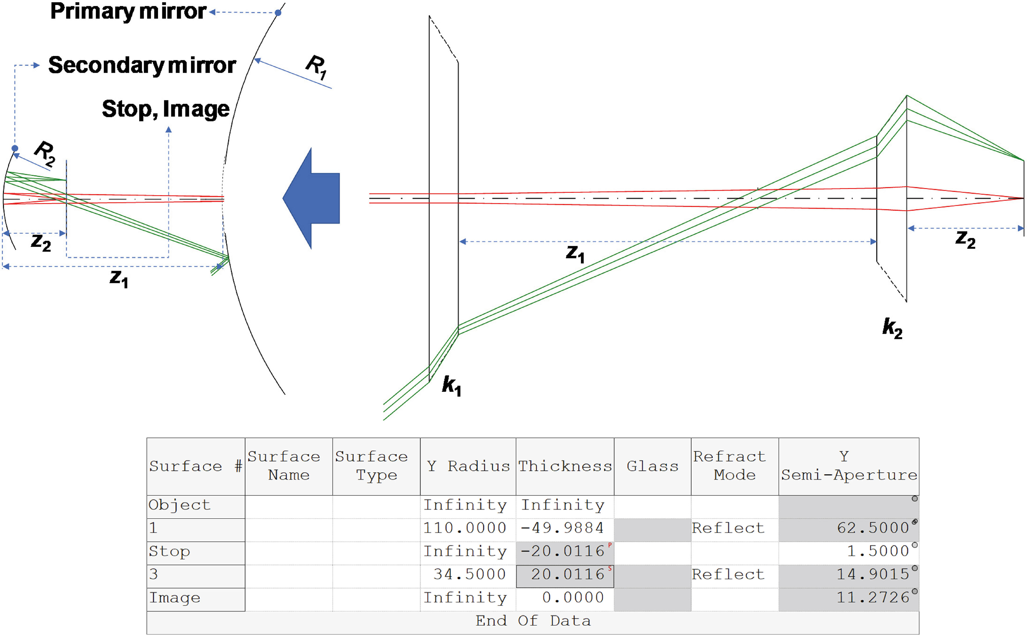
Under such conditions, the focal length of this optical system is found to be approximately 8.8 mm, and the optical path is shown in Fig. 1.
Figure 1.
Optical layout of paraxial design for wide-angle system.
If designed as shown in Fig. 1, the light source should be placed on the image plane. However, this is not possible due to mechanical interference. Therefore, this must be considered during the design of our relay system. In the relay system, the image formed by the optical system shown in Fig. 1 should be reduced to the size of the light emitting diode (LED). However, if the reduction magnification is high, many mirrors should be used for optical aberration correction. To homogenize the light from the LED, a glass rod with an entrance and exit surface area ratio of four should be used. The most easily available and inexpensive glass rod has an entrance aperture of 6.25 mm
(4)
(5)
Figure 2.
Optical layout for relay system.
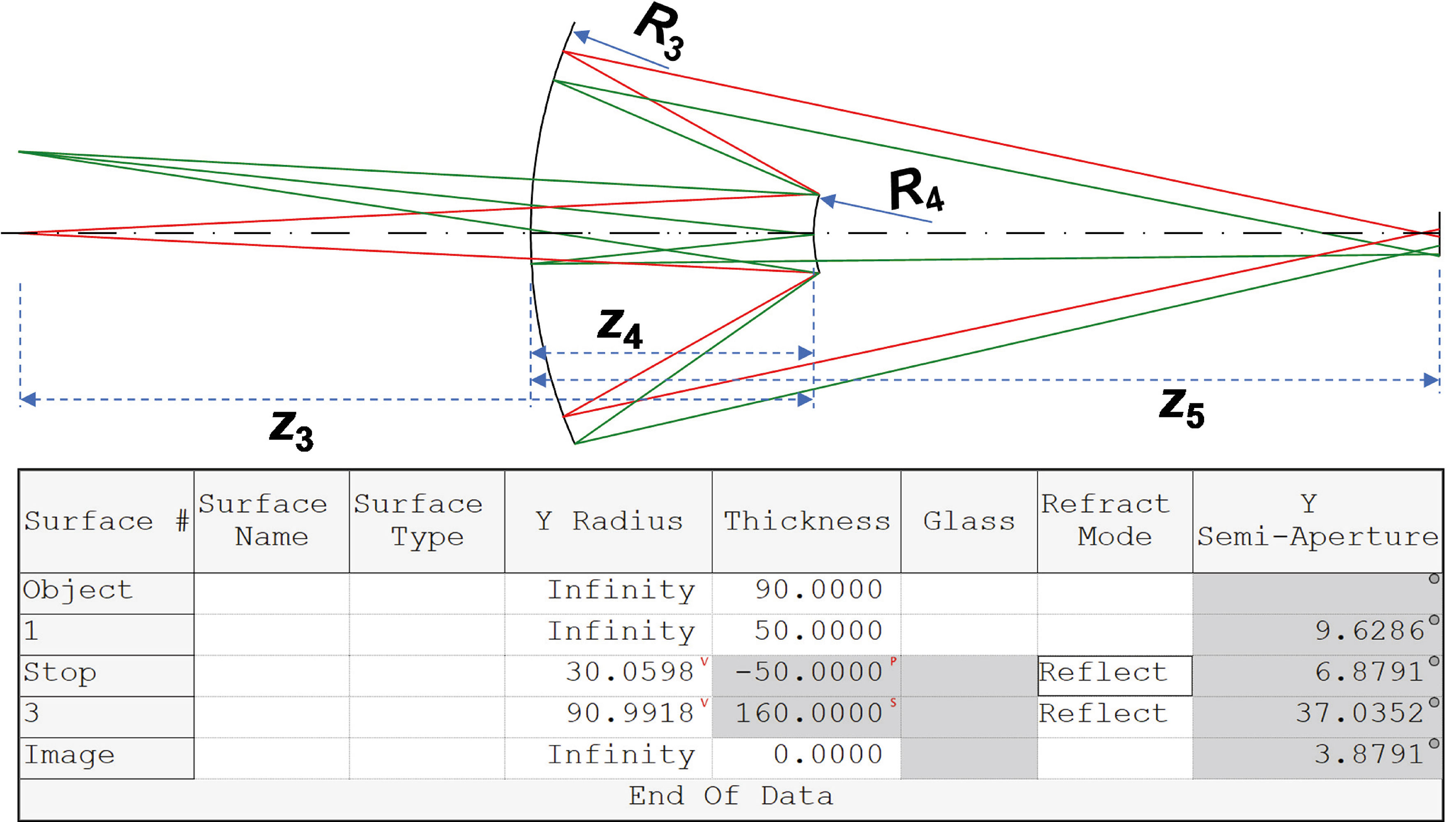
Figure 3.
Optical layout for coupled system.
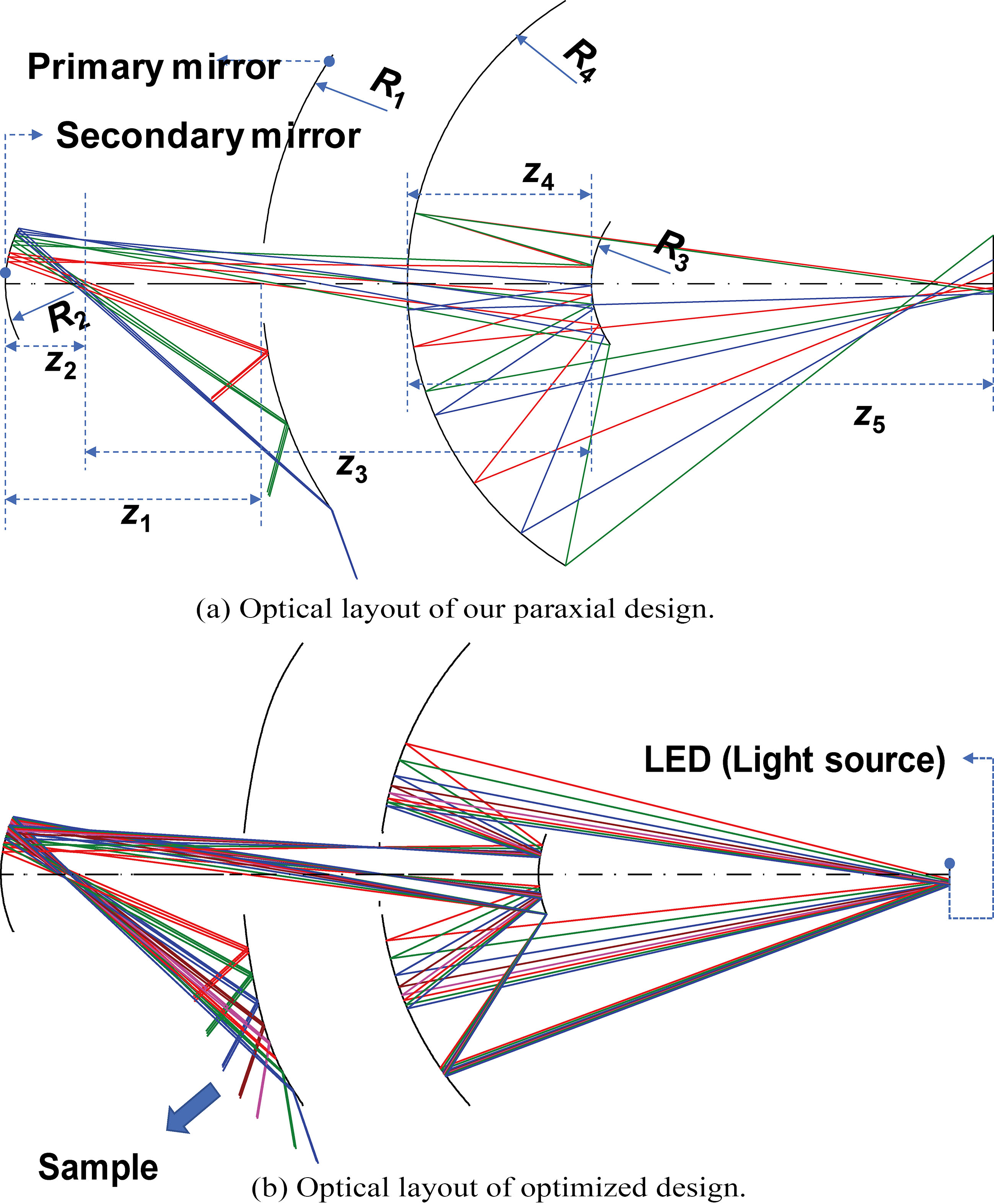
Figure 4.
Ray fan of our optimized system.
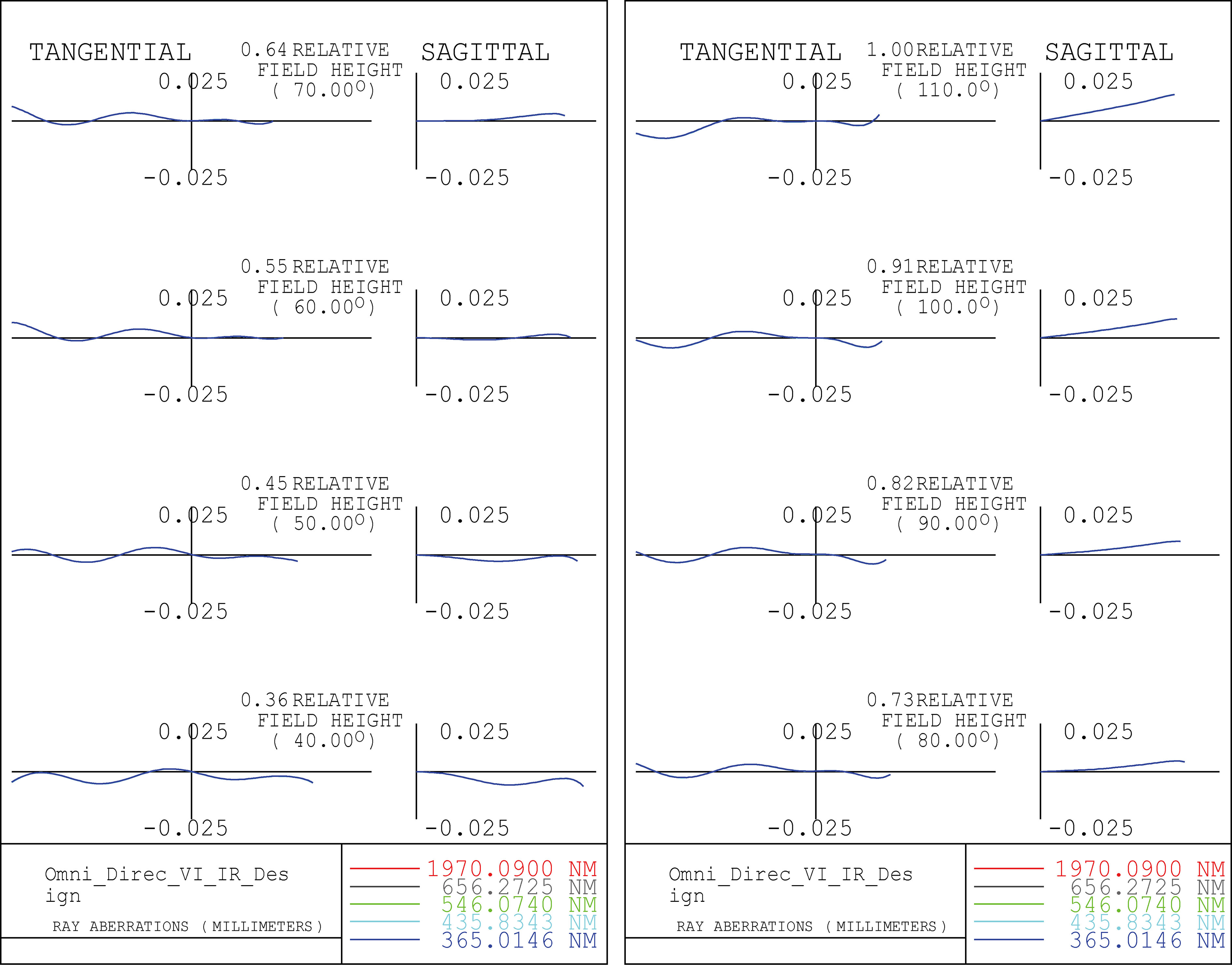
Figure 5.
3D optical layout for our optimized system.
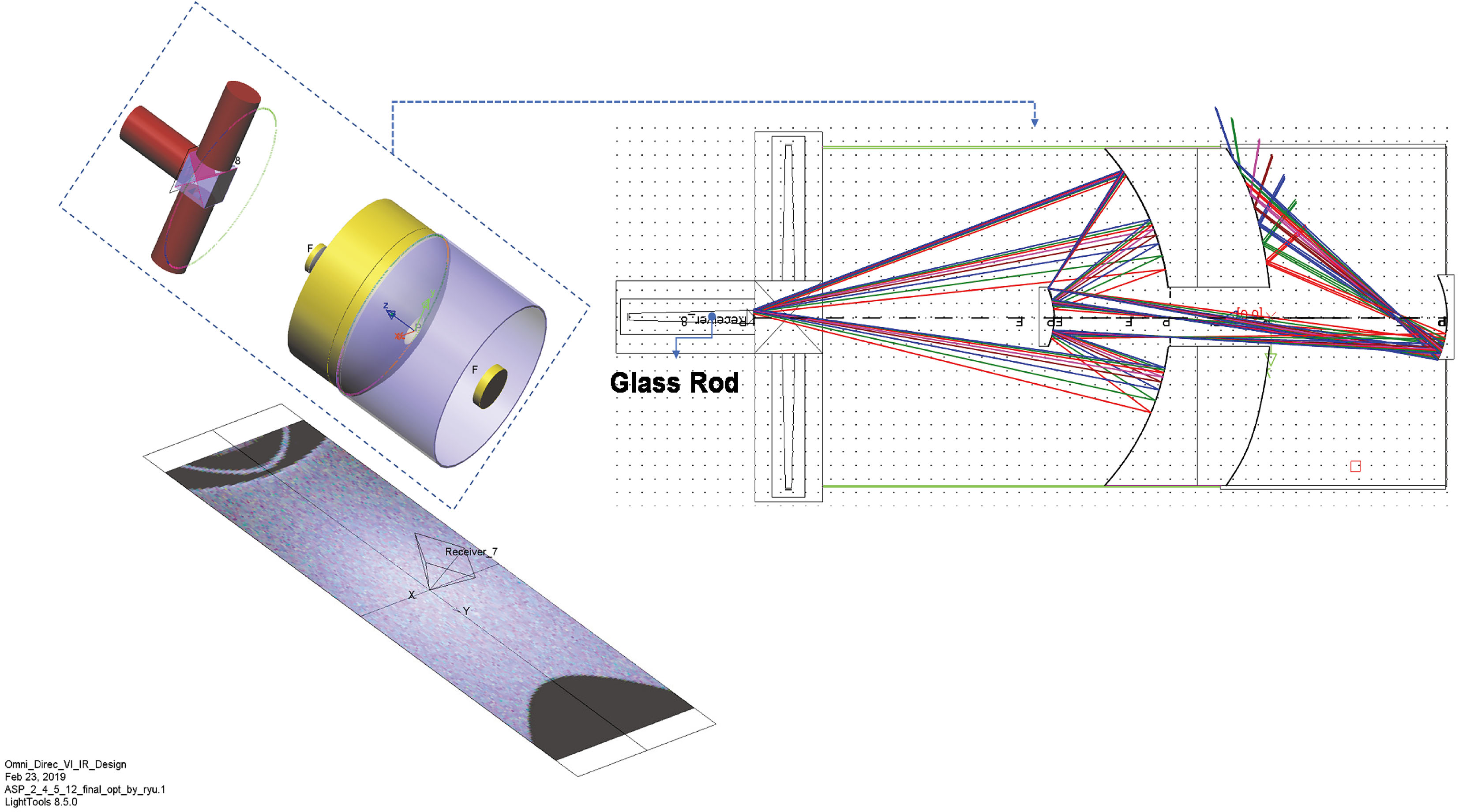
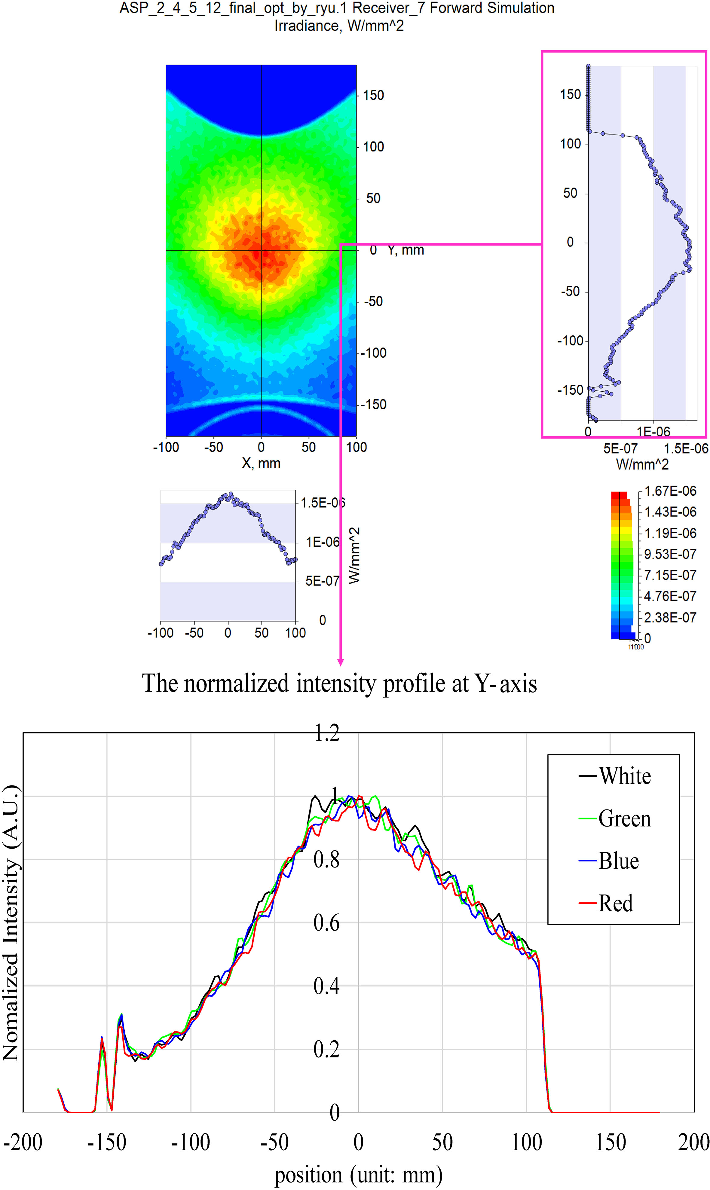
Figure 6.
Intensity distribution and normalized intensity profile.
In Eqs (4) and (5),
3.Results and discussion
3.1Optimization process
In general, the paraxial design is the result of determining the initial shape and spacing of the lens or mirror [28]. Therefore, the target performance is barely obtained. To correct this, the light beam should be focused while changing the shape and spacing of the mirror gradually. In acoustic-resolution-based photoacoustic instruments, the light beam needs to be focused. Simultaneously, the ultrasonic transducers need to be covered to obtain the target information. On the other hand, a light ray passing through the optical system forms a spot on the image surface. Optimization in optical design means minimizing the size of these spots. The spot size is a function of the curvature and spacing of the mirror, and optimization is the process of solving the nonlinear simultaneous equations for the spot size. The optical path of the optimized optical system and the paraxial design determined in Section 2 are shown in Fig. 3. This process is meaningful because low chromatic aberration within the target area could deteriorate the resolution in the photoacoustic instruments. As shown in Fig. 3, because the optical system consists only of the reflective surface, there is no change in the focus position as a result of the wavelength. Therefore, it is useful to generate high resolution with low chromatic aberrations in the photoacoustic instruments.
3.2Performance verification
The developed multispectral photoacoustic instruments have high chromatic aberrations when using the LED lights with multiple wavelength [16, 29]. However, this designed optical system can be expected to have no chromatic aberration because there is no change in focal position with respect to wavelength. This is highly desirable. In fact, Fig. 4 shows a ray fan in optical design software. As shown in Fig. 4, it can be seen that there is no chromatic aberration from the infrared (IR) region to the ultraviolet region.
On the other hand, by combining LEDs with these optical systems, we confirmed the intensity distribution of light at specific locations. An X-cube prism may be required to use LEDs of various wavelengths. The optical system with an LED and a glass rod is shown in Fig. 5.
The intensity distribution at a position 150 mm away from the optical axis in the vertical direction is shown in Fig. 6. The figure below shows the normalization based on the maximum at each wavelength, and the profile is almost constant regardless of the wavelength. Since the optical system without chromatic aberration is used, it is possible to obtain the same intensity distribution of light by using X-cube and glass rod and synthesizing light sources of different wavelengths. Simulation results show that the region with the strongest light intensity is within 80 mm in diameter from the center position of the sample. Adequate intensity distributions within a 150 mm range for red, green, and blue LED lights are enough to cover the samples for the photoacoustic instruments.
4.Conclusion
A chromatic aberration-free optical system using reflective mirrors was designed for multispectral photoacoustic instruments. The LED light sources are cost-effective and relatively safe compared to the traditional laser light sources used in photoacoustic instruments. Therefore, the photoacoustic instruments using LED light sources have been designed. Because different wavelengths are needed for different tissue characterization, multi-spectral photoacoustic instruments have been developed. However, the currently developed multispectral photoacoustic instruments have high chromatic aberrations, thus deteriorating optical resolution. Therefore, we developed a new type of multispectral optical design using a reflective mirror instead of the refracted optical lens used in conventional systems. Because we constructed a system with only a reflective surface, an aberration-free optical system was achieved. These results were confirmed from aberration plots and a normalized intensity profile. In the optical design, the intensity distribution at a position 150 mm away from the optical axis in the vertical direction exhibited adequate light intensity values. Therefore, the developed chromatic aberration-free optical system using a reflective mirror is a potential candidate for use in multispectral photoacoustic instruments.
Acknowledgments
This research was supported by the Basic Science Research Program through the National Research Foundation of Korea (NRF) funded by the Ministry of Science, ICT and Future Planning (NRF-2017R1C1B1003606) and the Ministry of Education (NRF-2017R1D1A3B03029119).
Conflict of interest
None to report.
References
[1] | He Z. Optimization of acoustic emitted field of transducer array for ultrasound imaging. Bio-Med Mater Eng. (2014) ; 24: (1): 1201. |
[2] | Shung KK. Diagnostic Ultrasound: Imaging and Blood Flow Measurements. Boca Raton, FL, USA: Taylor & Francis; (2015) . |
[3] | Kaminow I, Li T, Willner AE. Optical Fiber Telecommunications VB: Systems and Networks. Amsterdam, Netherlands: Elsevier; (2010) . |
[4] | Lee J-H, Kim YN, Park H-J. Bio-optics based sensation imaging for breast tumor detection using tissue characterization. Sensors. (2015) ; 15: (3): 6306-23. |
[5] | Lee J, Sevag Packard RR, Xu H, Kang H, Baek KI, Jen N, Jay Kuo C, Chi NC, Ho C-M, Li R. Light-sheet microscopy to elucidate hemodynamic forces and modulation of cardiac trabeculation: implications for embryonic contractile function. J Clin Invest. (2016) ; 30: (1_supplement): 554.3-.3. |
[6] | Emelianov SY, Li P-C, O’Donnell M. Photoacoustics for molecular imaging and therapy. Phys Today. (2009) ; 62: (8): 34-9. |
[7] | Wang LV. Photoacoustic Imaging and Spectroscopy. Boca Raton, FL, USA: CRC press; (2009) . |
[8] | Beard P. Biomedical photoacoustic imaging. Interface Focus. (2011) ; 1: (4): 602-31. |
[9] | Jeong JJ, Choi H. An impedance measurement system for piezoelectric array element transducers. Measurement. (2017) ; 97: : 138-44. |
[10] | Li X, Wei W, Zhou Q, Shung KK, Chen Z. Intravascular photoacoustic imaging at 35 and 80 MHz. J. Biomed. Opt. (2012) ; 17: (10): 106005. |
[11] | Zhu B, Xu J, Li Y, Wang T, Xiong K, Lee C, Yang X, Shiiba M, Takeuchi S, Zhou Q. Micro-particle manipulation by single beam acoustic tweezers based on hydrothermal PZT thick film. AIP Adv. (2016) ; 6: (3): 035102. |
[12] | Choi H, Ryu J, Kim J. A novel fisheye-lens-based photoacoustic system. Sensors. (2016) ; 16: (12): 2185. |
[13] | Li L, Yeh C, Hu S, Wang L, Soetikno BT, Chen R, Zhou Q, Shung KK, Maslov KI, Wang LV. Fully motorized optical-resolution photoacoustic microscopy. Opt Lett. (2014) ; 39: (7): 2117-20. |
[14] | Zhou Y, Yao J, Wang LV. Tutorial on photoacoustic tomography. J. Biomed. Opt. (2016) ; 21: (6): 061007. |
[15] | Lin L, Zhang P, Xu S, Shi J, Li L, Yao J, Wang L, Zou J, Wang LV. Handheld optical-resolution photoacoustic microscopy. J. Biomed. Opt. (2016) ; 22: (4): 041002. |
[16] | Cao R, Kilroy JP, Ning B, Wang T, Hossack JA, Hu S. Multispectral photoacoustic microscopy based on an optical-acoustic objective. Photoacoustics. (2015) ; 3: (2): 55-9. |
[17] | Razansky D, Distel M, Vinegoni C, Ma R, Perrimon N, Koster RW, Ntziachristos V. Multispectral opto-acoustic tomography of deep-seated fluorescent proteins in vivo. Nat Photon. (2009) ; 3: (7): 412-7. |
[18] | Yao J, Wang LV. Photoacoustic microscopy. Laser Photonics Rev. (2013) ; 7: (5): 758-78. |
[19] | Choi H, Ryu J-M, Yeom J-Y. Development of a double-gauss lens based setup for optoacoustic applications. Sensors. (2017) ; 17: (3): 496. |
[20] | Jenkins FA, White HE. Fundamentals of Optics. Noida, India: Tata McGraw-Hill Education; (1957) . |
[21] | Choi H, Yeom J-Y, Ryu J-M. Development of a multiwavelength visible-range-supported opto-ultrasound instrument using a light-emitting diode and ultrasound transducer. Sensors. (2018) ; 18: (10): 3324. |
[22] | Zappe H. Fundamentals of Micro-optics. Cambridge, United Kingdom: Cambridge University Press; (2010) . |
[23] | Pedrotti FL, Pedrotti LS. Introduction to Optics. Englewood Cliffs, NJ, USA: Prentice-Hall (1993) . |
[24] | Choi H, Ryu J, Yeom J-Y. A cost-effective light emitting diode-acoustic system for preclinical ocular applications. Curr Op Photon. (2018) ; 2: (1): 59-68. |
[25] | Walker BH. Optical Design for Visual Systems. Bellingham, WA, USA: SPIE Press; (2000) . |
[26] | Mahajan VN. Optical Imaging and Aberrations: Part I: Ray Geometrical Optics. Bellingham, WA USA: SPIE Press; (1998) . |
[27] | Smith WJ. Modern Optical Engineering. New York, NY, USA: McGraw-Hill Education; (2007) . |
[28] | Kidger MJ. Intermediate Optical Design. Bellingham, WA, USA: SPIE Publications; (2004) . |
[29] | Adachi Y, Hoshimiya T. Photoacoustic imaging with multiple-wavelength light-emitting diodes. Jpn J Appl Phys. (2013) ; 52: (7S): 07HB6. |


