
Development of a visual information to auditory information transformation system for ambulation assistance
Abstract
BACKGROUND:
Assistant equipment for the visually impaired has a white cane. If the information in the three-dimensional space is transmitted by sound, the blind can draw a three-dimensional space.
OBJECTIVE:
This study developed “Visual System,” an ambulation aid/guide for the blind that transforms visual-spatial information into auditory information, and verified its utility. Unlike conventional systems, which are in essence simple collision-warning systems, Visual System helps the visually impaired to recreate their surroundings and to be cognizant of the location and proximity of obstacles.
METHODS:
Ten subjects with normal vision (mean age: 32.4 years; male-to-female ratio: 6 to 4) were selected for blind tests. The subjects were instructed to detect and avoid obstacles presented in various three-dimensional settings. Prior to the tests, experiments were conducted to determine the distance to each subject. Upon completion of Visual System-based detection training, obstacles were presented and tests conducted. For evaluation, the subjects’ vertical position detection, horizontal position detection, distance detection, and overall performance success were each evaluated.
RESULTS:
The total performance scores ranged between 88 (lowest) and 100 (highest), with a mean score of 91.5.
CONCLUSIONS:
The results indicate that Visual System as a product can assist the visually impaired in their daily functioning.
1.Introduction
The ultimate goal of computer vision is to realize the functions of the human visual system through computers. The most fundamental task thereof is finding or identifying three-dimensional objects from input visual information and data. In computer vision research, studies on how to effectively identify and track objects in an image are extremely important as their findings can be applied to many associated applications that utilize image processing, such as surveillance systems, and for calibration of the posture and position of mobile robots.
Image registration for stereo vision systems can be categorized into area-based techniques and feature-based methods. The former approach locates tie-points between pairs of stereo images against a particular reference frame, called a window, and utilizes specific processes such as sum of absolute difference (SAD), sum of squared difference (SSD), and mean of absolute differences (MAD) [1]. Current research efforts in the field include electronic travel aid (ETA), which utilizes electronic and electrical technologies designed to ensure full functioning for persons with visual impairments, and robotic travel aid (RTA), which incorporates ETA into robotics. ETA utilizes various electronic sensors to obtain visual information, which it then translates to information that can be used by the visually impaired [2]. The development of ETA technologies locally began in a pioneering design project called ultrasonic glasses for the visually impaired, which first started at Inha University in the mid-1980s. Subsequently, Openeyes [3], which enables the visually impaired to recognize human faces, rows of letters, and obstacles using cameras attached to a pair of glasses, was developed. In 2000, Korea Advanced Institute of Science and Technology (KAIST) developed RTAS, an RTA system for guiding blind persons, on a mobile robotic platform invented by the U.S.-based company Pioneer [4]. The primary objective of this study is to assist blind or visually impaired people to safely move among obstacles and other hazards faced by them in daily life. To investigate the performance of the whole strategy, several trials have been conducted on the multi-sensor structure for different materials. The assistance device in this work will tell the user about the distance of the obstacle from the user, and various types of materials are distinguished based on light intensity phenomenon for the indoor environment. In the distant future, it can be extended to a system to suit outdoor environments. Also, the audio output to the user can be given using earphones [5]. The primary objective of this study is to assist blind or visually impaired people to move safely. It provides reliable feedback about the surrounding environment by vibrotactile mapping. The combined motion of the user and a moving obstacle give an accurate perception of its trajectory. To accomplish a perfectly wearable system, the miniaturization should be improved on the sensors and the actuators [6]. However, the problem with the products developed to date is that they are in essence walking alarm systems that provide simple information indicating whether obstacles are ahead.
In the SAD image-registration algorithm, registration points are determined by evaluating an image mask of the target image against the image mask of a reference image and obtaining the minimum value of the total sum (SAD value) of the differences in each pixel value between the two images. Equation (1) is used to compute this SAD value [7, 8, 9]:
(1)
where,
SAD-based algorithms calculate the value of
This study utilized stereo cameras and a SAD algorithm, an area-based image matching process, to obtain spatial information and create a system that transforms visual information into auditory information. The system developed and verified in this study is more than a simple collision-warning system. The developed system transforms visual-spatial information into auditory information using stereo cameras to help the visually impaired recreate the visual inputs.
2.Subjects and methodology
2.1Method
2.1.1Stereo vision systems
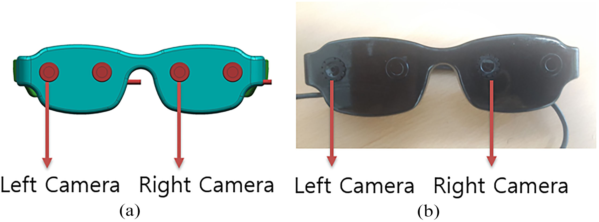
A stereo vision system (Fig. 1) derives three-dimensional distance information from the obtained disparities between pairs of corresponding points that match the right and left images obtained by two cameras installed in a three-dimensional space [11, 12]. Image-registration methods are roughly divided into three categories: area-based, feature-based, and energy-based algorithms. This study used a SAD algorithm, one of the most commonly used area-based registration techniques, to obtain three-dimensional spatial information.
2.1.2Mechanism of Visual System
Visual System uses two Logitech PC Cameras, has a Samsung Exynos dual core 1 GHz central processing unit (CPU), and was developed in C language with Linux as the operating system. Visual System consists of a detection unit, a computing unit, and a display unit. The detection unit (the stereo vision system) utilizes the two PC cameras (Fig. 1). The computing unit employs the SAD-based algorithm to transform the obtained three-dimensional spatial data into auditory information. The display unit was created using stereo earphones.
Figure 1.
Developed eyeglass stereo camera using PC camera conformity to level the camera and minimize errors. (a) Stereo camera 3D model. (b) Developed stereo camera.
The system employs the following procedure: Matrix-like distance sensors obtain distance information simultaneously from segments of the three-dimensional space ahead. This obtained information is immediately transformed into auditory information and displayed as outputs. During horizontal and vertical movement, Visual System detects associated changes and modifies the auditory information to reconstruct the spatial information ahead. In this study, the three-dimensional spatial information is obtained as a data matrix that is then transformed into auditory information.
2.2Proposed technique for transforming visual information into auditory information
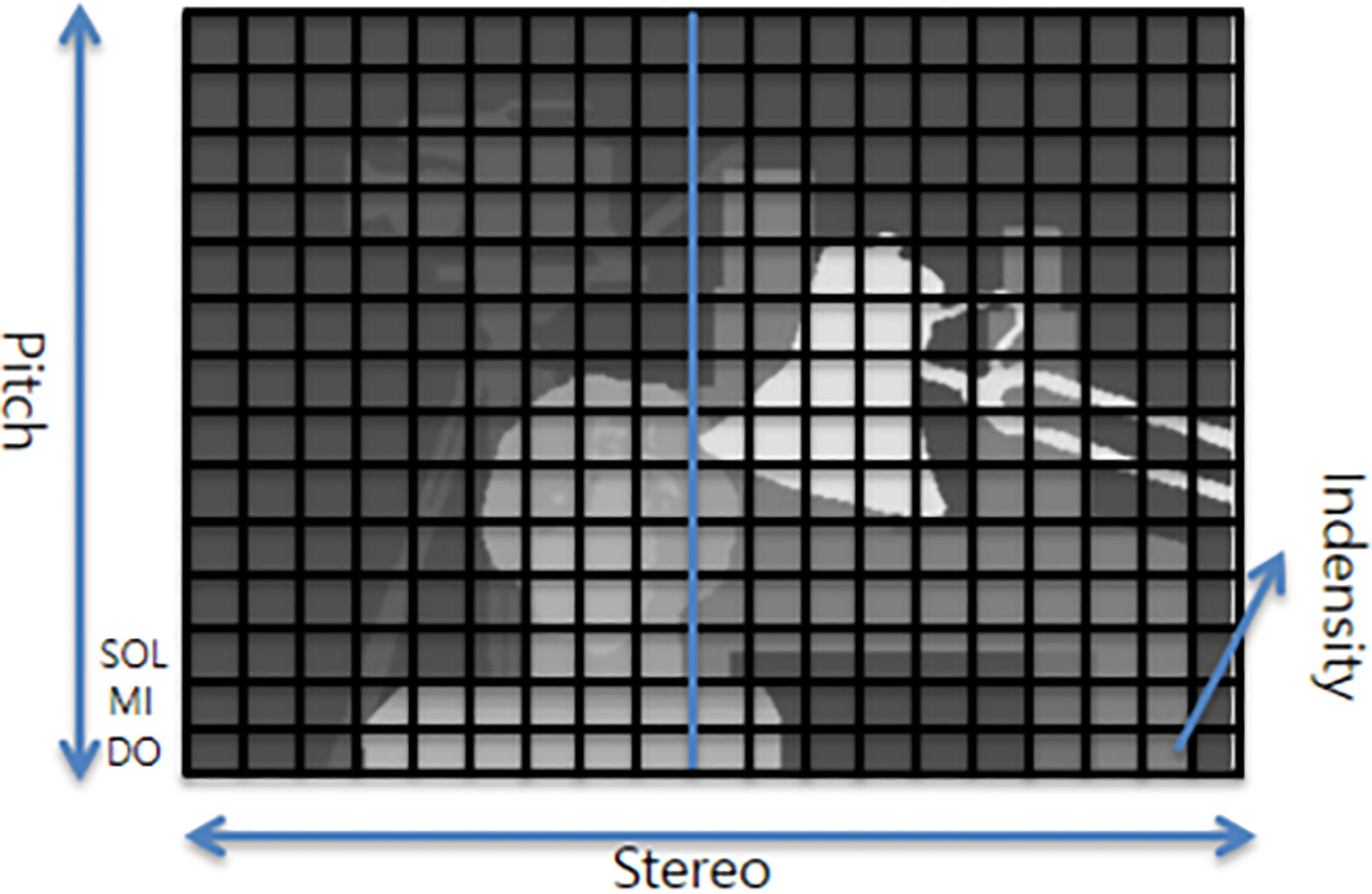
The proposed technique for transforming visual-spatial information into auditory information is illustrated in Fig. 2. The technique entails transforming the location each object in three-dimensional space, i.e., its vertical position, horizontal position, and distance, into auditory signals using sound intensity, pitch, and stereo. The right and left image outputs on Visual System are input to the SAD-based algorithm based on Eq. (1), where the object’s two-dimensional x- and y-position and distance for each position can be indicated in terms of signal strength. This study utilized three properties of sound in order to achieve the transformation of spatial information into audio signal. First, right and left stereo sound was used to distinguish the object’s right from left. Simultaneously, the pitches (high vs. low) changed continuously according to the position shifts of the object on a two-dimensional x- and y-axis. To identify even the most minute changes, the solfège pitches on the piano, Do, Mi, and Sol, were utilized spanning all five octaves of the keyboard. For instance, an object located high on the y-axis would sound like a corresponding solfège pitch in Octave 5 and an object located low on the axis a pitch in Octave 1, thereby allowing recognition of the object’s vertical position. Finally, the object’s distance information was transformed into sound intensity, where a louder sound would indicate that the object is near, whereas a softer sound would signify a greater distance. The use of all three dimensions ultimately allows recognition of the object’s horizontal position, vertical position, and distance.
Figure 2.
Transformation of auditory information: pitch is denominated by 1–5 octaves (do mi sol), stereo by left/right distinction, and intensity is used for distinction.
2.3System realization and test and evaluation methods
2.3.1Realization of Visual System
Visual System obtains a 400
Preprocessing procedures were implemented to eliminate errors and to obtain three-dimensional spatial information. In the preprocessing process, the radial distortion and tangential distortion of the lens were eliminated, and the angle and distance between the two cameras adjusted to find corresponding points with the same features in the left and right images. The distortion is corrected using linear interpolation using pixels adjacent to the image. In the linear interpolation method, pixel values are calculated by applying a weight inversely proportional to the distance to pixel values of neighboring four coordinates. Through this procedure distance images are obtained. The dimension of the images fed into both cameras was 400
The brightness or luminosity of the image detected in each of the pixels that constitute the three-dimensional spatial information was allocated to the intensity of sound. For x-axis pixels, output signals were defined to indicate the disparity in stereo. With y-axis pixels, the signals were allocated in terms of frequency differences and vertical positions on the y-axis (upper vs. lower). The outputs (440 Hz, 494 Hz, 523 Hz, 587 Hz, 659 Hz, 698 Hz, 784 Hz) were delivered to both ears through stereo earphones that distinguish right from left.
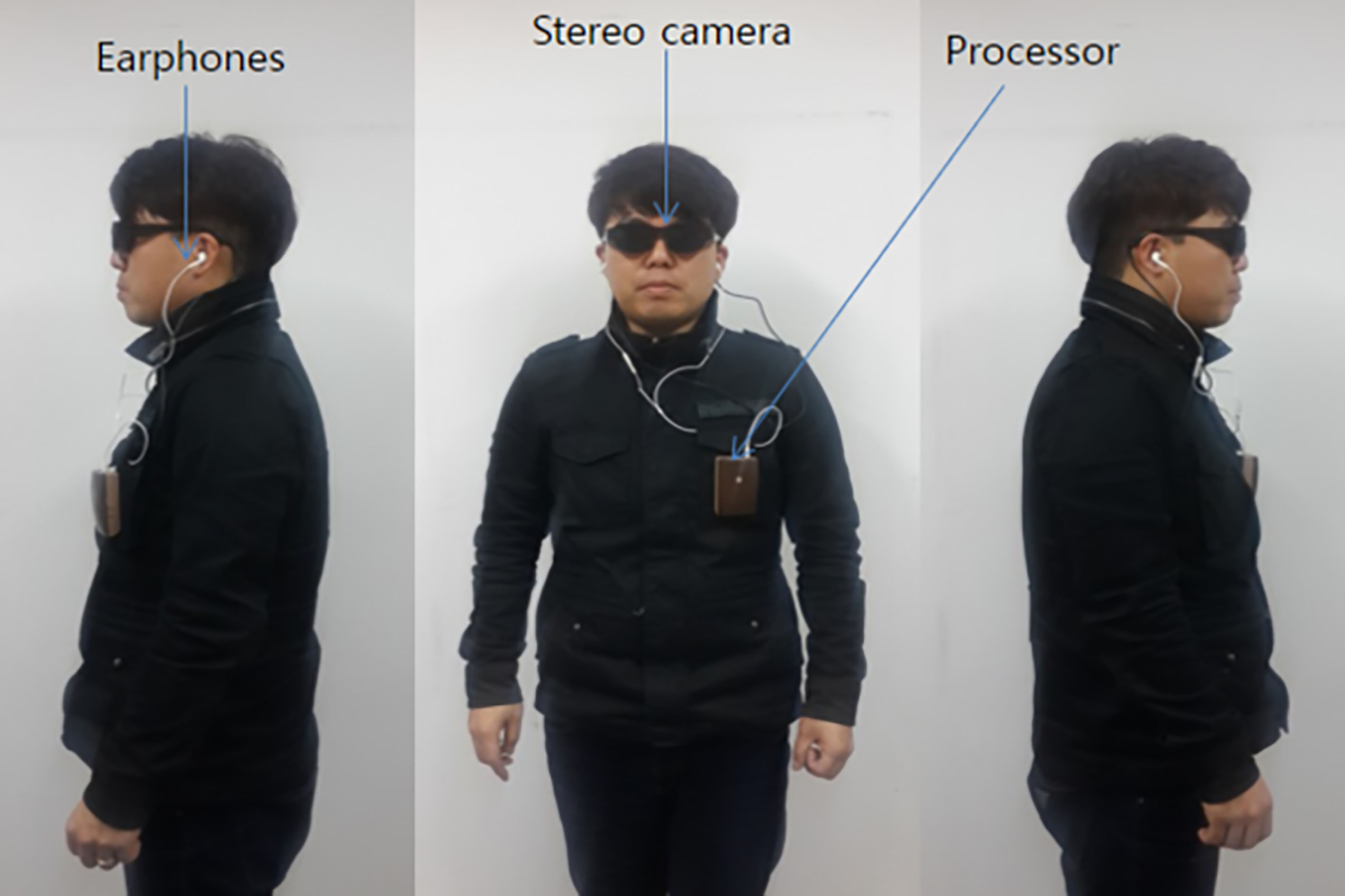
The components of Visual System are shown in Fig. 3. Visual System is operated as follows: The user puts on the pair of glasses to which a centrally processed stereo camera (integral, battery-operated type) is attached, wears the earphones in both of his/her ears, and covers the eyes using shades. On encountering an obstacle while ambulating, its location in three-dimensional space is indicated through sound stimuli that allow the user to determine its proximity, whether it is on the right- or left-hand, and whether it is located above or below him/her.
Figure 3.
Components of Visual System on a user. The chest has the main system; earphones and stereo camera (in the pair of glasses) are also present.
2.3.2Experimental methodology
This study was approved by our university’s Institutional Review Board (IRB approval number: 2017-0079). Visual System experiments were performed on a total of 10 subjects. The experiments were conducted with the human subject’s understanding and consent, and prior safety-related training and with security personnel in the room.
2.3.2.1. Tests conducted to measure distance
As shown in Fig. 4, tests were conducted to help the subject determine his/her location in terms of distance and to determine how far he/she is located from another person. The tests were aimed at meeting the ultimate goal of this study, which is to transform the visual-spatial information into auditory information. Figure 4 illustrates that the distances between the subjects were varied during the measurement, i.e., 1 m, 2 m, and 3 m. Depending on the distance, the values of the three-dimensional spatial information would increase, resulting in a louder sound indicating shorter distance. The experiments proceeded utilizing various loudness levels to distinguish the corresponding distances such that the subjects could picture their surroundings in their minds with increasing confidence. The subjects, wearing the Visual System kit, were requested to raise their hands each time they detected a change in sound intensity that would indicate that the distance between them and the sound source was increasing from 30 cm to 3 m.
Figure 4.
Experiment to determine distance from 50 cm to 3 m while wearing Visual System.
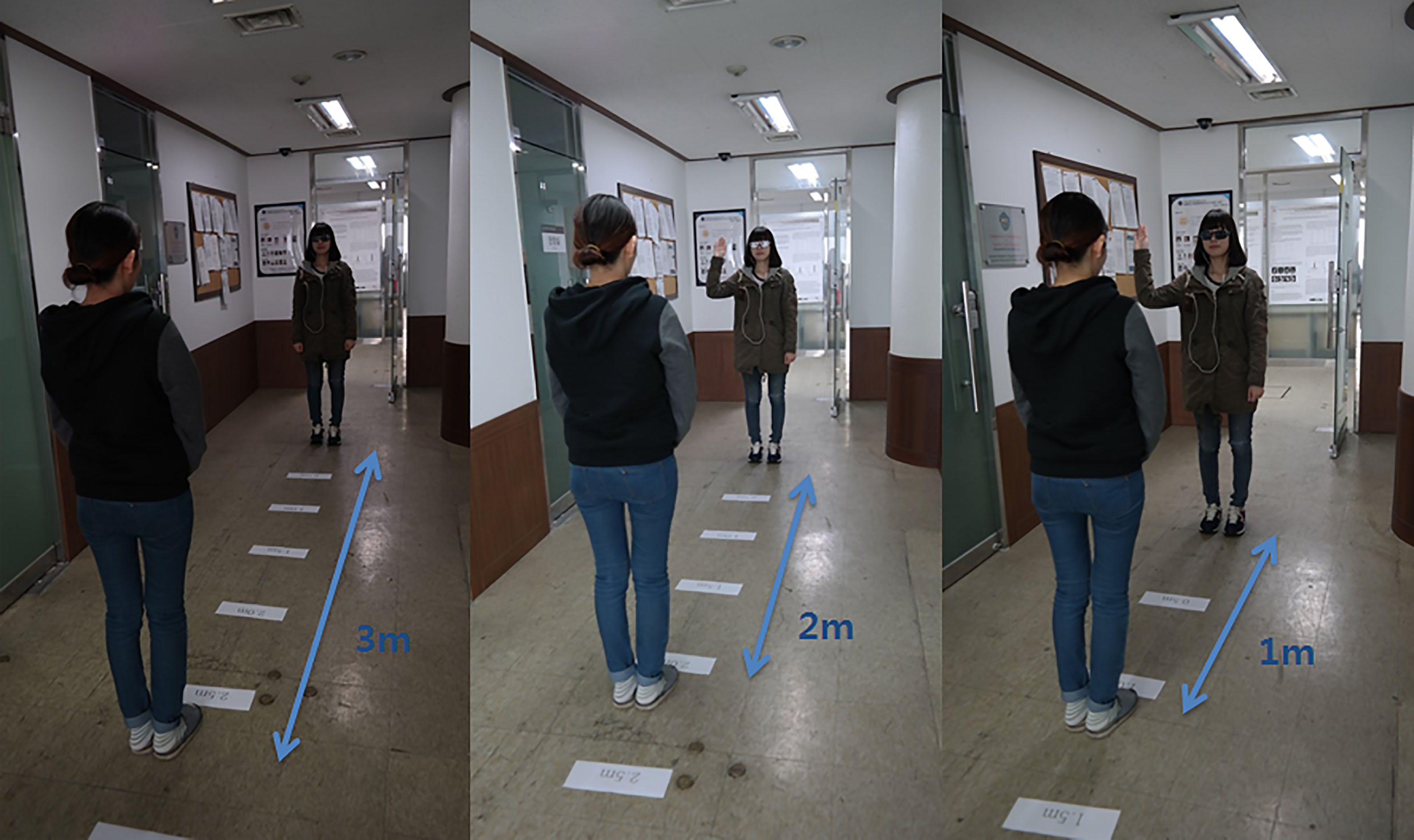
Figure 5.
Subject wearing Visual System and passing obstacles while being aware of the objects.
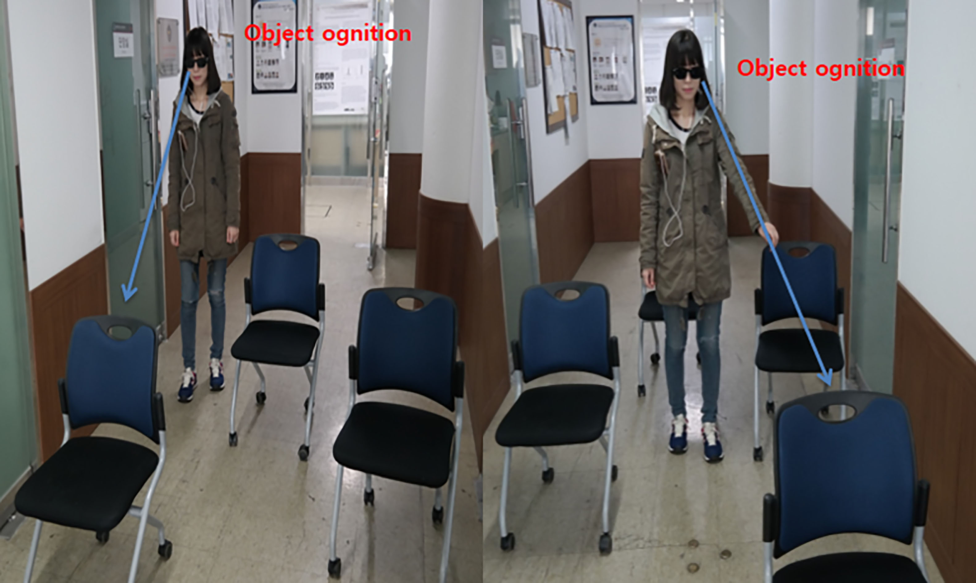
2.3.2.2. Indoor testing
Figure 5 shows a subject who participated earlier in the distance-detection tests now engaged in the obstacle-detection tests. The subjects were instructed to wear the stereo earphones in their ears such that they could detect obstacles with greater success, and to pass between the obstacles considering the information received about their surroundings. The subjects put on the Visual System kit before starting their participation in these tests.
2.3.3Evaluation method
Obstacle-detection tests served as the basis for evaluating vertical detection, horizontal detection, distance detection, and overall performance success. Ten normally functioning individuals (mean age: 32.4 years: male to female ratio: 6 to 4) with no problem recognizing and determining auditory stimuli participated in the experiments. The selected participants also did not have any problem having their eyes blindfolded. Upon the subjects’ wearing the stereo earphones, the experiments began. First, the subjects were given distance-detection tests, and those who exhibited no problem with those tests were allowed to move on to the indoor test. Ten out of the 12 subjects passed the distance-detection tests, and two failed because of compromised recognition ability (the most important factor in the experiment design) as they were unable to detect slight differences in two auditory stimuli. The indoor testing was aimed at measuring the subjects’ ability to detect obstacles. None of the remaining 10 subjects failed this test. The subjects’ vertical obstacle-detection, horizontal obstacle-detection, distance detection, and overall performance success were rated on a scale of one to five, with one being the difference between one rating level and the next. The experiment was carried out five times, and it was 1 point for success and 0 points for failure. The scores obtained were then converted to percentages.
3.Results
The subjects’ vertical and horizontal detection, distance detection, and overall performance success were evaluated based on their responses recorded in the footages (Figs 4 and 5). The highest level of detection performance occurred in the horizontal detection tasks, where the highest and lowest percentages were 100 and 86, respectively. The distance-detection tasks showed the lowest level of participant performance. Problems identified were distance-dependent; specifically, the farther an object was, the lower was the detection in terms of stereo vision. However, because failure in the subjects’ detection ability was observed only for distances greater than 3 m, it was not considered as being problematic for actual ambulation. Analysis of the total scores indicated that the maximum performance was 100% and the minimum 86%, with a 91.5% mean. Thus, subjects were able to recognize their surroundings and determine distances that made them aware of their surroundings with a success rate of approximately 91.5% (Table 1).
Table 1
Performance evaluation scores
| Vertical detection | Horizontal detection | Distance detection | Overall performance | Sum | |
| Subject 1 | 4 | 5 | 5 | 5 | 19 |
| Subject 2 | 4 | 5 | 3 | 4 | 16 |
| Subject 3 | 5 | 5 | 4 | 5 | 19 |
| Subject 4 | 5 | 5 | 4 | 5 | 19 |
| Subject 5 | 4 | 5 | 5 | 4 | 18 |
| Subject 6 | 5 | 5 | 4 | 5 | 19 |
| Subject 7 | 4 | 5 | 5 | 5 | 19 |
| Subject 8 | 5 | 5 | 4 | 4 | 18 |
| Subject 9 | 4 | 5 | 5 | 5 | 19 |
| Subject 10 | 4 | 5 | 4 | 4 | 17 |
| Total | 44/50 | 50/50 | 43/50 | 46/50 | 183/200 |
| Percentages | 88% | 100% | 86% | 92% | 91.5% |
4.Discussion
This study was conducted with the objective of transforming visual information into auditory information in three-dimensional space. The proposed visual system enables users to determine the location of objects and their proximity in 3D space. Users are made aware of the direction of the objects and are able to distinguish distances according to the surrounding environment. The results of the tests conducted prove that the system enables users to recognize the 3D space by converting the visual information into auditory information pitch, stereo, and intensity. Vertical detection experiments have a different sound pitch. The sound pitch was from 1 octave to 5 octaves. An average of 88% of objects could be distinguished. To distinguish the sound pitch, learning time was required. The longer the learning time, the better the distinction of the location of things. Horizontal detection experiments were performed using sound stereo. The left/right distinction was able to locate the object with an average of 100%. Sound stereo has shorter learning time than sound Pitch. Distance detection experiments have different sound volumes according to the pixel intensity. The distance distinction showed an average of 86%. To distinguish the distances, the distance information should be configured well. There is a limitation in constructing the distance information by using the stereo camera. However, the distinction was good at a short distance of 3 m. Vertical detection, horizontal detection, and distance detection were simultaneously performed in overall performance. The average result is 92%. When the experiment was conducted in a complex environment, the left/right distinction was correct. It took a lot of time to distinguish between the top and bottom. The problem seems to be lack of learning about the sound pitch. Distance distinction did not cause any problems.
Visual assistive devices are being developed in a variety of forms (electronic orientation aids, electronic travel aids, and position locator devices). Depending on the distance, EyeRing FineReader is developed at about 1 m, Ultracane and Smart Cane at 2 m
5.Conclusion
In this study, Visual System, an aid system for the visually impaired that transforms three-dimensional spatial information into auditory information, was developed and its efficacy for guiding blind persons successfully verified. Based on the test results obtained by subjects without visual impairments, we can extrapolate that given sufficient training, blind persons (who invariably have better auditory sensitivity than non-blind persons) would have excellent performance. Given the purpose of Visual System, which is to reconstruct the spatial information of the three-dimensional space ahead (i.e., visual cognition target) based on auditory information, the spatial resolution could be increased by multiplying the number of factorized matrices of the information detected in stereo vision, provided the users’ proficiency with the system is improved. The resulting applications are applicable not only as visual aids to the blind but also as visual information acquisition tools in blind spots and visual assistance for nighttime military operations (such as movement of troops). Furthermore, when combined with GPS systems, the applications could be implemented as global navigation tools through induction technology based on self-localization and destination routing [8]. In particular, using GPS in conjunction with Visual System in underground locations, in high-rise buildings, between buildings, and on narrow streets, which are all affected by poor GPS reception, could be the optimum solution for the visually impaired, providing users with greater comfort and convenience.
Acknowledgments
This research was supported by the Technology Transfer and Commercialization Program through the INNOPOLIS Foundation, funded by the Ministry of Science, ICT and Future Planning, (2015DG0008, Development of Multisensor-based Smart Glasses for Providing Visual Information). We would like to thank Editage (www.editage.com) for English language editing and publication support.
Conflict of interest
None to report.
References
[1] | Sekhar VC, Bora S, Das M, Manchi PK, Josephine S, Paily R. Design and implementation of blind assistance system using real time stereo vision algorithms. In: 29th International Conference on VLSI Design and 15th International Conference on Embedded Systems (VLSID); Kolkata, India. IEEE; Jan 4–8 (2016) , pp. 421-6. doi.org/10.1109/VLSID.2016.11. |
[2] | Kotani S, Mori H, Kiyohiro N. Development of the robotic travel aid “HITOMI”. Robot. Auton. Syst. (1996) ; 12: (1-2): 119-128. doi.org/10.1016/0921-8890(95)00067-4. |
[3] | Kang S, Lee S. Visual aid technology of wearable computer system for the visually impaired. Kor. Brain Soc. J. (2001) ; 1: (1): 127-137. |
[4] | Hur S, Bang S, Seo J, Choi H, Kim T, Lee N, et al. Development of analysis program for visual reconstruction devices using auditory perception. Kor. Mult. Soc. J. (2010) ; 13: (1): 58-65. |
[5] | Vigneshwari C, Vimala V, Sumithra G. Sensor based assistance system for visually impaired. International Journal of Engineering Trends and Technology. (2013) ; 4: (10): 4338-4343. |
[6] | Cardin S, Thalmann D, Vexo F. A wearable system for mobility improvement of visually impaired people. The Visual Computer. (2007) ; 23: (2): 109-118. |
[7] | Lee S, Yi J, Kim J. Real-time stereo vision on a reconfigurable system. In: Hämäläinen TD, Pimentel AD, Takala J, Vassiliadis S, eds. Embedded Computer Systems: Architectures, Modeling, and Simulation. SAMOS 2005. Lecture Notes in Computer Science, vol 3553. Berlin, Heidelberg: Springer; (2005) , pp. 299-307. doi.org/10.1007/11512622_32. |
[8] | Sebe N, Lew MS. Maximum likelihood stereo matching. In: International Conference on Pattern Recognition; 2000 Sep 3–7; Barcelona, Spain. IEEE; Vol. 1, (2002) , pp. 900-903. doi: https://doi.org/10.1109/ICPR.2000.905573. |
[9] | Ambrosch K, Kubinger W, Humenberger M, Steininger A. Hardware implementation of an SAD based stereo vision algorithm. In: 2007 IEEE Conference on Computer Vision and Pattern Recognition. Minneapolis, MN, USA, 17–22 June (2007) , pp. 1-6. dio. 10.1109/CVPR.2007.383417. |
[10] | Dong X, Wang G, Pang Y, Li W, Wen J, Meng W, Lu Y. Fast efficient algorithm for engancement of low lighting video. In: 2011 IEEE International Conference on Multimedia and Expo. Barcelona, Spin, 11–15 July (2011) , pp. 1-6. doi: 10.1109/ICME.2011.6012107. |
[11] | Chiang MH, Lin HT, Hou CL. Development of a stereo vision measurement system for a 3D three-axial pneumatic parallel mechanism robot arm. Sensors. (2011) ; 11: (2): 2257-2281. doi: 10.3390/s110202257. |
[12] | Scharstein D, Szeliski R. A taxonomy and evaluation of dense two-frame stereo correspondence algorithms. Int. J. Comp. Vis. (2002) ; 47: (1-3): 7-42. doi: 10.1109/SMBV.2001.988771. |
[13] | Elmannai W, Khaled E. Sensor-based assistive devices for visually-impaired people: Current status, challenges, and future directions. Sensors. (2017) ; 17: (3): 565. |
[14] | Dokmani I, Tashev I. Hardware and algorithms for ultrasonic depth imaging. In: IEEE International Conference on Acoustics, Speech and Signal Processing (ICASSP); Florence, Italy. IEEE; May 4–9 (2014) . pp. 6702-6706. doi.org/10. 1109/ICASSP.2014.6854897. |


