
Inverse kinematic analysis and trajectory planning of a modular upper limb rehabilitation exoskeleton
Abstract
BACKGROUND:
Stroke is the most prevalent neurological disease and often leads to disability. Stroke can affect a person’s daily life, for example, its typical feature is the decline in the patient’s upper limbs. In order to reduce the sports injury of stroke patients, the best method is to carry out certain rehabilitation training.
OBJECTIVE:
In this paper, inverse kinematic analysis and trajectory planning of a modular upper limb rehabilitation exoskeleton are proposed.
METHODS:
The reverse coordinate system method is applied to solve inverse kinematics of the exoskeleton with a non-spherical joint in the wrist. For verifying the effectiveness of the algorithms, the smooth round-trip trajectory movement in joint place is designed and simulated.
RESULTS:
The reverse coordinate system method can simplify the calculation process compared with the normal coordinate system. Smooth round-trip trajectory planning is simulated to generate a smooth trajectory curve.
CONCLUSIONS:
The developed inverse kinematics algorithm and trajectory planning method are effective.
1.Introduction
Stroke is the most prevalent neurological disease and often leads to disability. Stroke can affect a person’s daily life, for example, its typical feature is the decline in the patient’s upper limbs [1]. In order to reduce the sports injury of stroke patients, the best method is to carry out certain rehabilitation training [2]. The conventional therapies are usually performed by professional medical therapists, which is labour-intensive and, therefore, expensive.
To overcome these shortcomings of manually assisted arm training, lots of upper limb exoskeleton systems were investigated and designed to help patients. A 5 degrees-of-freedom (DOF) upper limb exoskeleton was designed by Martinez and Retolaza [3]. Perry et al. [4] proposed an anthropomorphic 7-DOF active exoskeleton robot (EXO-7). Mao and Agrawal [5, 6] developed a cable driven 5-DOF exoskeleton robot (CAREX) based on three light weight cuffs. Nef et al. [7] designed a therapy exoskeleton (ARMin III) with an ergonomic shoulder actuation that is slightly complex.
The exoskeletons mentioned above are traditional serial structure, and they have enough workspace and easy control. However, compared with parallel mechanism, they have small stiffness, low precision and weak bearing capacity. Frankly speaking, the exoskeletons that have been developed now are mostly in series mechanism, but less in parallel mechanism. Klein et al. [8] developed a 4-DOF pneumatically-actuated parallel upper limb exoskeleton used for rehabilitation. Takaiwa and Noritsugu [9] used a pneumatic parallel robotic arm to design a wrist rehabilitation device. However, pneumatic actuators are less accurate though they need less maintenance.
To solve these limitations, based on human anatomy and biological principles, we designed a 6-DOF modular upper limb rehabilitation exoskeleton, which is driven by cable and with parallel actuated joints in this paper. We adopted new differential mechanisms design method which enhanced the compactness and ergonomics of the device are improved. The mechanical structure allows rehabilitation training of both left and right arm of the patients. Besides, it can achieve patients’ composite rehabilitation training which contains both a single joint and multi-joints.
In the control aspect of exoskeleton, a basic method is PID feedback control which usually doesn’t have accurate control results [10]. Some complex approaches, such as sliding mode control [11], fuzzy logic technique [12], impedance or admittance control [13, 14], have been used. Although the effect is better than PID, the algorithms are based on force model and implement difficultly. With the development of computer hardware system, electromyographic (EMG) [15], which can measure patients’ musculation to detect patients’ motion intention, is introduced in upper limb exoskeleton. But EMG method needs expensive measuring equipment. Inverse kinematics, which are usually used in the manipulators and can implement accurate position and trajectory planning, are extended in the exoskeleton [16, 17]. However, the inverse solutions above are only for series exoskeleton configuration. In this paper, reverse coordinate method, that is, inverse kinematics is obtained not directly though solving the inverse kinematics, is used to calculate the inverse kinematics of our parallel mechanical structure. In [18], teach-and-replay mode was tested to define reference trajectories. However, it would cost much time to record and extract the trajectory. This paper proposes a smooth trajectory planning method of two round-trip trajectory. The advantages of this method are giving a solution quickly and the flexibility of being able to redefine human trajectory.
2.Modular design of upper limb exoskeleton
2.1Mechanical design
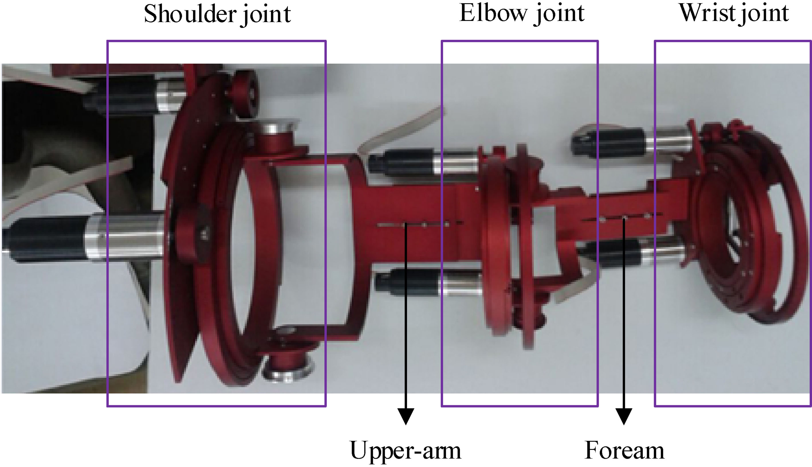
For purpose of imitating human movement, we designed a parallel actuated 6-DOF modular upper limb rehabilitation exoskeleton, as shown in Fig. 1. It contains three modules with the same principle and structure. Each joint exists as an independent module, which can achieve not only single-joint rehabilitation training but also multi-joint composite training. Each module including two motors can achieve two DOF of upper limb, and each DOF is achieved by the combined effect of these two motors.
Figure 1.
Upper limb rehabilitation exoskeleton.
2.2Decoupling of joint angles
In order to determine the relationship between two motors and the degree of freedom of the joint in the module, the shoulder joint is used as an example for decoupling joint angles. The shoulder joint module achieves shoulder abduction/adduction and flexion/extension. Schematic diagram of its mechanism principle is shown in Fig. 2a.
Figure 2.
The shoulder joint of exoskeleton.
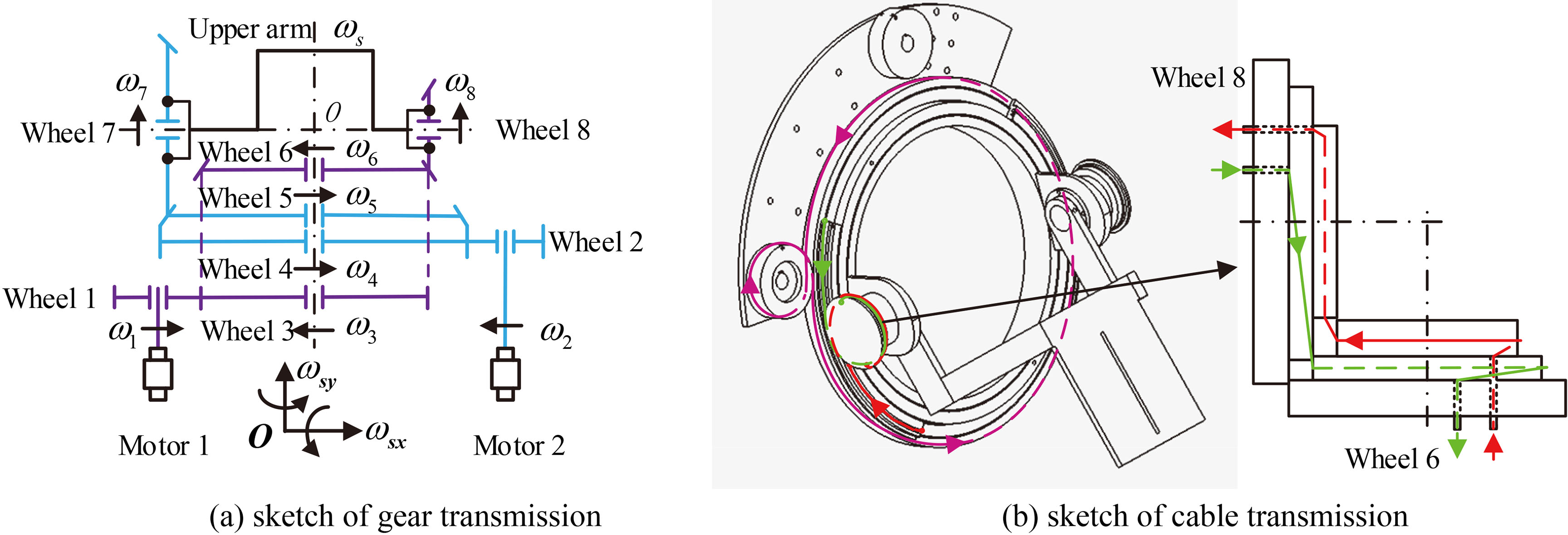
Point
The upper arm is fixed to the wheel 7 and the wheel 8, so we can get the following equation.
(1)
The angular velocities of the upper limb relative to wheel 5 and wheel 6 are denoted with
(2)
By means of projecting the Eq. (2) to
(3)
In order to make the rehabilitation exoskeleton achieve the needs of high precision, miniaturization, and lightweight, the gear-driven transmission is replaced by cable-driven transmission as shown in Fig. 2b. As a pair of parallel wheels, the winding method of wire rope between wheel 2 and wheel 4 is similar to the number 8 shown as the pink line, which is also happened between wheel 1 and wheel 3. The driving mode between wheel 8 and wheel 6 or wheel 7 and wheel 5 is realized by a pair of wire ropes represented red line and green line.
3.Analysis of inverse kinematics
3.1The reverse coordinate method
In order to analyze inverse kinematics, the parallel mechanical structure can be equivalent to a serial configuration. For a mechanism configuration where the three axes of the end intersect at one point, the inverse kinematic solutions are easily obtained directly. However, the exoskeleton we designed is the intersection of the two axes in the wrist joint. Considering that there is a spherical joint in the shoulder, the reverse coordinate method [19] is applied to complete the inverse kinematic solutions.
The typical method of establishing coordinate system is the Denavit-Hartenberg (referred to as DH) coordinate system [20] and the modified DH (M-DH) coordinate system. It’s the first step to establish DH coordinate system for exoskeleton model. Then, by inverting the shoulder joint and the wrist joint of original exoskeleton an inverted exoskeleton can be acquired. For this inverted exoskeleton the coordinate system established is the M-DH coordinate system. Therefore, this reverse coordinate method combines two coordinate systems cleverly, simplifying the process of inverse kinematic solutions of 6-DOF exoskeleton we designed.
The M-DH coordinate system of the inverted exoskeleton is shown in Fig. 3, and the specific parameters and values are listed in Table 1.
Figure 3.
The M-DH coordinate system.
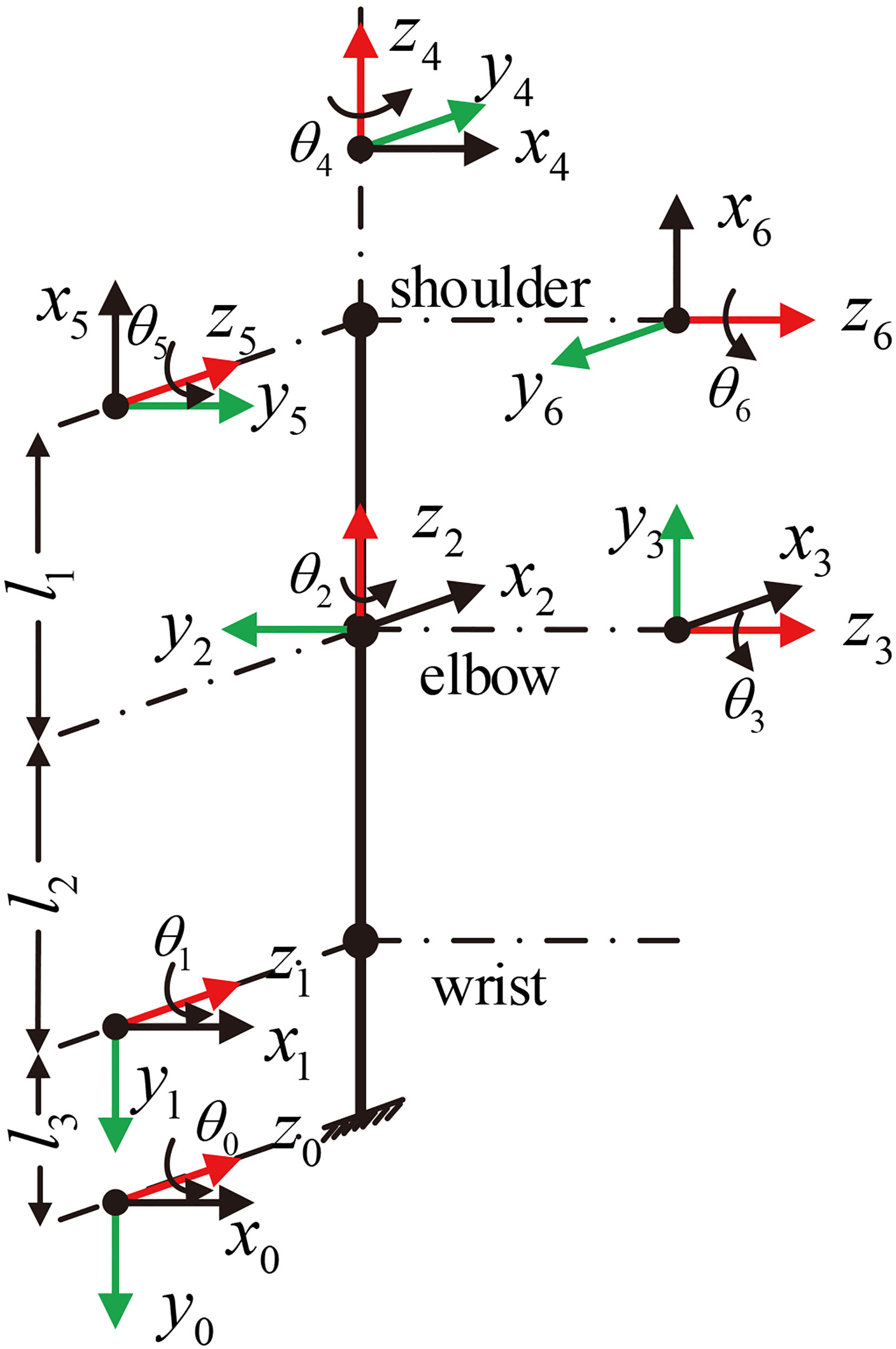
Table 1
The M-DH parameters and values
| Link |
|
|
|
|
|---|---|---|---|---|
| 1 |
| 0 | 0 |
|
| 2 |
|
| 90 | 0 |
| 3 |
| 0 | 90 | 0 |
| 4 |
|
| 0 | |
| 5 |
| 0 | 0 | |
| 6 |
| 0 | 0 |
The transformation matrix of the original exoskeleton and the inverted exoskeleton are represented by
(4)
(5)
Since the relationship between the inverted exoskeleton and the original exoskeleton is converse we can get the following equation.
(6)
Matrix
(7)
The joint angle of original exoskeleton
(8)
Therefore, the solutions of inverse kinematics of the original exoskeleton can be obtained by calculating the joint variables of the inverted exoskeleton robot.
3.2Solutions of inverse kinematics
To find an inverse kinematic solution for a given end effector configuration,
(9)
3.2.1Solutions of 1st rd
The left and right sides of the Eq. (9) are multiplied by
(10)
By solving the elements of the fourth column on both sides of Eq. (10), the angles of 1
(11)
(12)
where
3.2.2Solution of 2nd
By moving the
(13)
where
3.2.3Solution of 4th
Then move
(14)
where * represents a meaningless element for solving 4
Now, it needs to be further analyzed as hereunder mentioned:
If
(15)
where
3.2.4Solutions of 5th th
The left and right sides of the Eq. (14) are multiplied by
(16)
where * represents a meaningless element for solving 5
The angles of 5
(17)
(18)
where
Based on the aforesaid calculation results the inverse kinematics solutions of the inverted exoskeleton are solved. Therefore, the inverse kinematics solutions of the original exoskeleton can be given according to Eq. (8).
4.Smooth trajectory planning
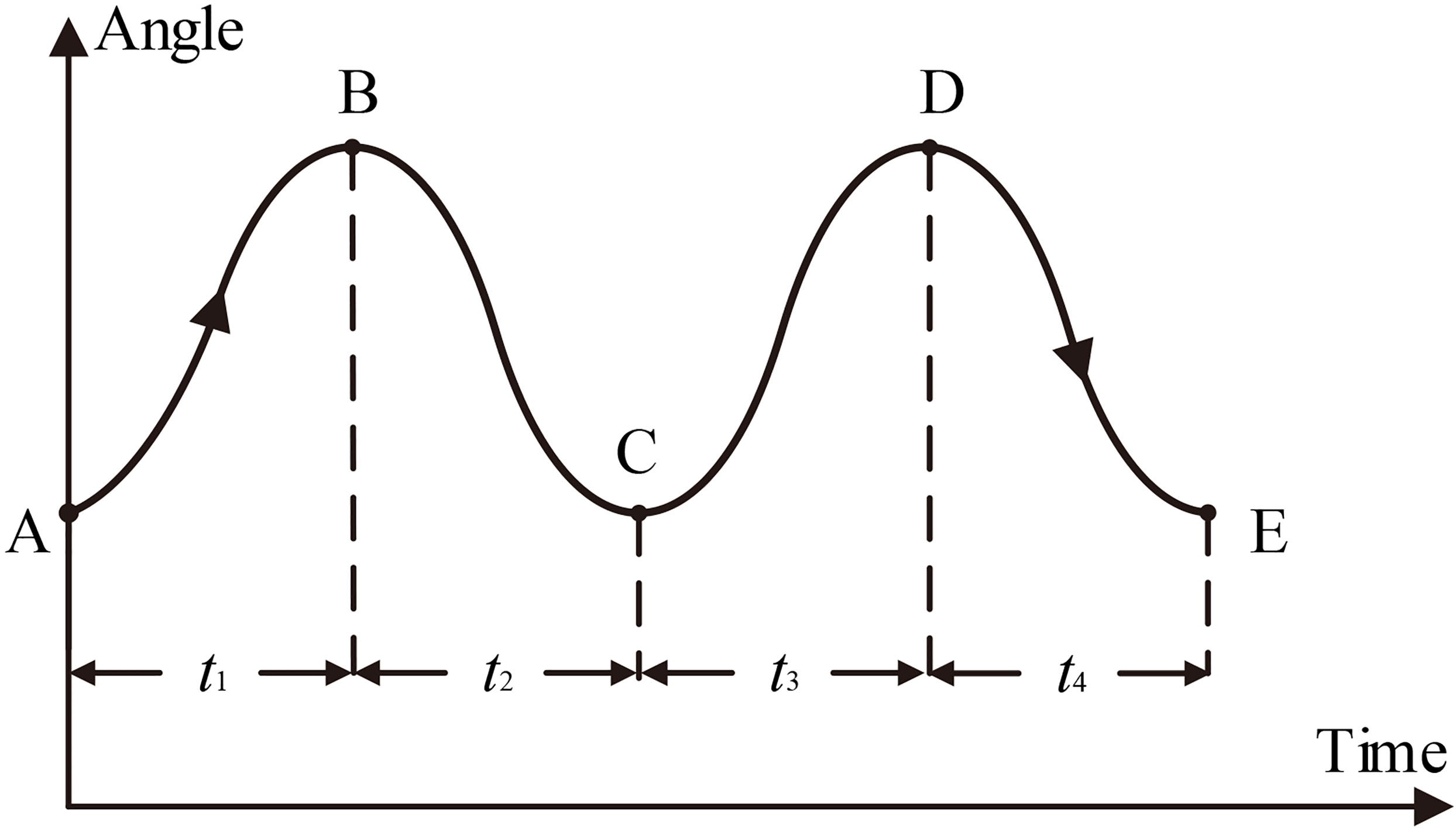
A new multi-cubic polynomial interpolation method by using the cubic polynomial interpolation principle is designed for two round-trip trajectory planning in joint place shown in Fig. 4. Position A to position E are the initial point, the middle points and the end point of the trajectory, respectively. The use of round-trip trajectory has enormous advantages in rehabilitation application, for example, the control ability of the motion trajectory can be improved by the accessibility of redefining polynomials and by the ability to reciprocate without interruption caused by a single trajectory.
Figure 4.
Two round-trip trajectory planning.
The form of the trajectory between every two positions is a third-order polynomial in time shown as Eq. (19). Therefore two round-trip trajectory planning consists of four cubic spline curves shown as Eq. (20), and the time of each spline curve is
(19)
where
(20)
Angular velocities and angular accelerations can be obtained from Eq. (19) as follow, respectively.
(21)
The four equations are obtained from the initial condition
(22)
At the intermediate points B, C, and D, the angles, angular velocities, and angular accelerations of the trajectory are continuous, so we can get the following twelve equations.
(23)
(24)
(25)
where
Figure 5.
Trajectory curve in angle, velocity, acceleration and end effector respectively.
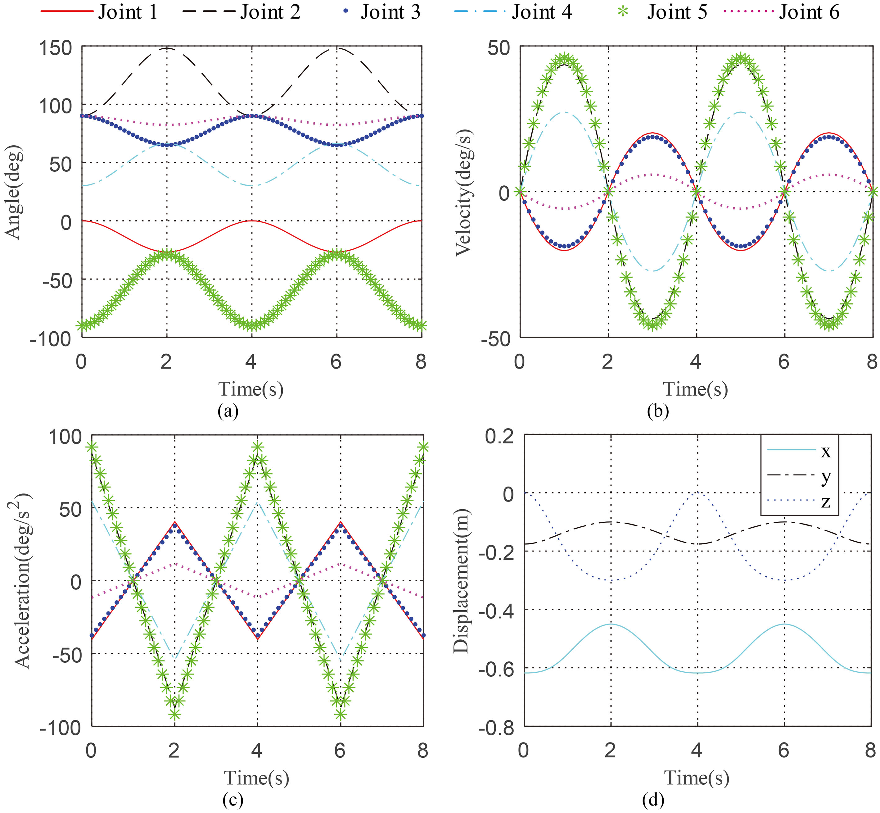
Then the twelve constants are substituted into Eqs (19) and (20) to obtain the smooth trajectory in angles, velocities and accelerations, respectively. Simulations are performed as below to verify the two round-trip trajectory planning reasonable. We set upper arm length
The curves of angles, velocities and accelerations of six joints and end effector are smooth from Fig. 5, which is beneficial to the rehabilitation of patients. Therefore, the proposed trajectory planning method is reasonable. When controlling the position of the exoskeleton, the velocity profile of the exoskeleton moving the desired position is equally or even more important than the accuracy of the final position. Then the exoskeleton should assist the upper limb of the subject to the desired position through a smooth trajectory during the patient’s rehabilitation training.
5.Discussion and conclusion
A new modular upper limb rehabilitation exoskeleton with parallel actuated joints is described in this paper. Each module represents one joint of human upper limb, which can achieve single-joint rehabilitation training and multi-joint complex training. It has the advantages of strong flexibility, compact structure, large working space and high precision. Then the reverse coordinate system method is applied to solve inverse kinematics of serial equivalence configuration of the exoskeleton. For the stability of the rehabilitation training process without saltation, smooth round-trip trajectory planning based on cubic polynomial interpolation method in joint space is simulated to generate a smooth trajectory curve, which meet the standards of upper limb movement characteristics. And the simulation results show that the developed inverse kinematics algorithm and trajectory planning method are effective. Future work will optimize structure and design a reasonable control system.
Acknowledgments
This work was supported by the National Key R&D Program of China (Grant no. 2017YFB1302301), and the Joint Research Fund (Grant no. U1613218&U1713201&U1613219) between the National Nature Science Foundation of China (NSFC) and Shenzhen.
Conflict of interest
None to report.
References
[1] | Fitle KD, Pehlivan AU, O’Malley MK. A robotic exoskeleton for rehabilitation and assessment of the upper limb following incomplete spinal cord injury. In: IEEE International Conference on Robotics and Automation. IEEE, (2015) : pp. 4960-4966. |
[2] | Hatem SM, Saussez G, Faille MD, et al. Rehabilitation of motor function after stroke: a multiple systematic review focused on techniques to stimulate upper extremity recovery. Frontiers in Human Neuroscience, (2016) , 10: (88). |
[3] | Martinez F, Retolaza I, Pujana-Arrese A, et al. Design of a five actuated DoF upper limb exoskeleton oriented to workplace help. In: IEEE Ras & Embs International Conference on Biomedical Robotics and Biomechatronics. IEEE, (2008) : pp. 169-174. |
[4] | Perry JC, Rosen J, Burns S. Upper-limb powered exoskeleton design. IEEE/ASME Transactions on Mechatronics, (2007) , 12: (4): 408-417. |
[5] | Mao Y, Agrawal SK. Design of a cable-driven arm exoskeleton (CAREX) for neural rehabilitation. IEEE Transactions on Robotics, (2012) , 28: (4): 922-931. |
[6] | Mao Y, Agrawal SK. Transition from mechanical arm to human arm with CAREX: A cable driven ARm EXoskeleton (CAREX) for neural rehabilitation. In: IEEE International Conference on Robotics and Automation. IEEE, (2012) : pp. 2457-2462. |
[7] | Nef T, Guidali M, Riener R. ARMin III – arm therapy exoskeleton with an ergonomic shoulder actuation. Applied Bionics & Biomechanics, (2009) , 6: (2): 127-142. |
[8] | Klein J, Spencer SJ, Allington J, et al. Biomimetic orthosis for the neurorehabilitation of the elbow and shoulder (BONES). In: IEEE Ras & Embs International Conference on Biomedical Robotics and Biomechatronics. IEEE, (2008) : pp. 535-541. |
[9] | Takaiwa M, Noritsugu T. Development of wrist rehabilitation device using pneumatic parallel manipulator. In: Energy Saving and New Application on Fluid Power-Proceedings of the First China-Japan Joint Workshop on Fluid Power. (2010) : pp. 2302-2307. |
[10] | Garrido J, Yu W, Soria A. Modular design and modeling of an upper limb exoskeleton. Biomedical Robotics and Biomechatronics. IEEE, (2014) : 508-513. |
[11] | Rahman MH, Ouimet TK, Saad M, et al. Development and control of a wearable robot for rehabilitation of elbow and shoulder joint movements. (2010) , 7500: (1): 1506-1511. |
[12] | Li Z, Su CY, Li G, et al. Fuzzy approximation-based adaptive backstepping control of an exoskeleton for human upper limbs. IEEE Transactions on Fuzzy Systems, (2014) , 23: (3): 555-566. |
[13] | Carignan C, Tang J, Roderick S. Development of an exoskeleton haptic interface for virtual task training. In: Ieee/rsj International Conference on Intelligent Robots and Systems. IEEE, (2009) : pp. 3697-3702. |
[14] | Gupta A, O’Malley MK. Design of a haptic arm exoskeleton for training and rehabilitation. IEEE/ASME Transactions on Mechatronics, (2006) , 11: (3): 280-289. |
[15] | Loconsole C, Dettori S, Frisoli A, et al. An EMG-based approach for on-line predicted torque control in robotic-assisted rehabilitation. Haptics Symposium. IEEE, (2014) : 181-186. |
[16] | Gook B, Rosen J. Kinematic analysis of 7 degrees of freedom upper-limb exoskeleton robot; with tilted shoulder abduction. International Journal of Precision Engineering & Manufacturing, (2013) , 14: (1): 69-76. |
[17] | Rar I. Inverse kinematics for upper limb compound movement estimation in exoskeleton-assisted rehabilitation. Biomed Research International, (2016) , 2016: : 1-14. |
[18] | Staubli P, Nef T, Klamroth-Marganska V, et al. Effects of intensive arm training with the rehabilitation robot ARMin II in chronic stroke patients: Four single-case. Journal of NeuroEngineering and Rehabilitation, (2009) , 6: (1): 46. |
[19] | Jiang L, Huo X, Liu Y, et al. An integrated inverse kinematic approach for the 7-DOF humanoid arm with offset wris. In: IEEE International Conference on Robotics and Biomimetics. IEEE, (2013) : pp. 2737-2742. |
[20] | Zhu Y, Wang T, Jin H, et al. Kinematics and singularity analysis of a novel 7-DOF humanoid arm based on parallel manipulating spherical joints[C]. In: IEEE International Conference on Mechatronics and Automation. IEEE, (2015) : pp. 1144-1149. |


