
Development and application of computer assisted optimal method for treatment of femoral neck fracture
Abstract
BACKGROUND:
To help doctors decide their treatment from the aspect of mechanical analysis, the work built a computer assisted optimal system for treatment of femoral neck fracture oriented to clinical application.
OBJECTIVE:
The whole system encompassed the following three parts: Preprocessing module, finite element mechanical analysis module, post processing module.
METHODS:
Preprocessing module included parametric modeling of bone, parametric modeling of fracture face, parametric modeling of fixed screw and fixed position and input and transmission of model parameters. Finite element mechanical analysis module included grid division, element type setting, material property setting, contact setting, constraint and load setting, analysis method setting and batch processing operation. Post processing module included extraction and display of batch processing operation results, image generation of batch processing operation, optimal program operation and optimal result display.
RESULTS:
The system implemented the whole operations from input of fracture parameters to output of the optimal fixed plan according to specific patient real fracture parameter and optimal rules, which demonstrated the effectiveness of the system.
CONCLUSIONS:
Meanwhile, the system had a friendly interface, simple operation and could improve the system function quickly through modifying single module.
1.Introduction
In the surgical treatment process of internal fixation for femoral neck fracture, selection of internal fixation mode is the only controlled variable. An ideal internal fixation mode can offer a relatively stable environment for fracture gap, and a proper strain stimulus in fracture gap is also benefit to fracture healing [1]. Therefore, selection of proper internal fixation is the key to the success of surgery. In the traditional internal fixation surgery for femoral neck fracture, doctors need to shoot X-ray film repeat to check surgical marker and position relationship between screw and femoral neck. In addition, the internal fixation mode is totally determined through experience of doctors, which neglect mechanical properties of femur [2]. However, the biomechanical properties of different internal fixation mode are an important influence on the internal fixation mode selection. Traditional analysis method of biomechanical study mainly focuses on in vitro experiments, which can not gain stress change information in vivo. Finite element method has many advantages on the performance of stress distribution in bone and joint and some other tissues, which gain satisfactory results. Zhao et al. used three dimensional finite element analysis results to predict collapse of femoral head, which offered effective data for clinical study and helped doctors select the best treatment plan [3, 4, 5]. Keyak and Rossi used finite element method to analysis different stress patterns inducing femoral fracture and found that torsional stress and shear stress played an important role in the occurrence of femoral fracture [6]. The study results of Cody et al. proved that finite element method was the best method to predict load on fracture through the comparison between QCT, DEXA and three dimensional finite element method [7]. Ota et al. used finite element method successfully simulated the femoral fracture process, which was helpful to understand the mechanism of fracture [8]. Wang and Guo offered evidence for election of proper internal fixation mode thorough the study of optimal method of internal fixation for femoral neck fracture [9].
In summary, all the studies to date were focused on the analysis for single internal fixation model. And for getting analysis results, doctors must be trained to master modeling and simulation methods of some software such as MIMICS, ANSYS. However, these software are not the ones especially for mechanical analysis of femoral neck fracture; they have a higher demand for doctors. To reduce the influence of invalid module, promote system analysis efficiency and decrease operation difficulty for doctors, research and development work of computer assisted optimal system for treatment of femoral neck fracture are carried out. The whole system encompasses the following three parts: preprocessing module, finite element mechanical analysis module, post processing module. Key problems needed to be solved include parametric modeling of bone, parametric modeling of fracture face, parametric modeling of fixed screw and fixed position; a good human-computer interaction interface design and parameter transmission between interface and analysis program; language nesting between VC++ and APDL; batch processing operation; display and optimization of batch processing results.
2.Materials and methods
2.1Design of computer assisted optimal system for treatment of femoral neck fracture
The main functions of the system were as follows. According to characteristic parameters of femoral neck input in system interface, internal fixation mode was decided. And then transfer these parameters to the APDL code command stream of femoral neck fracture mechanical analysis. By calling ANSYS software through background, modeling of bone (fracture face, fixation mode), grid division, load application and mechanics calculation were completed automatically. At last, results from finite element analysis were post processed and displayed on the system interface, which eventually helped doctors complete the optimization for internal fixation surgical plan of femoral neck fracture. The system was a convenient and user-friendly special finite element analysis system. Users only needed to care about the input data and optimal results. According to purposes above, the whole system was divided into following three parts: preprocessing module, finite element mechanical analysis module and post processing module.
ANSYS parametric design language can accomplish the development of each module program in the whole analysis process [10]. Using program written by APDL can realize parametric modeling, parametric grid division, parametric load applying, data post processing and eventually realized parametric finite element analysis [11]. The analysis for different design plan can be accomplished through modifying parameters in process of finite element analysis, which in return promoted analysis efficiency. The work used APDL language to complete program development based on the parametric design language characteristic. But program written by APDL language also had some defects, such as unclarity of program structure, the weakness of interface design. In ANSYS software, for every GUI operation, there was a corresponding operation command, which was difficult to remember. APDL file belonged to a script language and it was not intuitive. To make up these defects, in this paper, VC++ was used to encapsulate APDL language, generate command stream that can be recognized by ANSYS and improved ANSYS re-development technique.
2.2Design of preprocessing module
2.2.1Parametric modeling of bone
The work used Descartes global coordinate system. Length unit is meter (m), angle unit is degree (
The idea of parametric modeling of bone was to use parametric variable to substitute actual variable and to complete finite element analysis of variable structural parameter geometric model. At first, use geometric parameters to build solid model of each part of femur. The basis of the establishment of solid model was the general coordinates of Descartes. The part of femoral shaft model was built in rotating coordinates. The part of greater trochanter model and the part of femoral neck model were built in the general coordinates. The part of femoral head model was built in the mobile Descartes coordinate system. Then femoral geometric model was gained by Boolean operations forming entity.
2.2.2Parametric modeling of femoral fracture face
In the Descartes coordinates, work plane was rotated to fracture face thorough counter clockwise to 90-A1+C degree (A1 was fracture angle;
2.2.3Parametric modeling of internal fixation mode
Internal fixation mode selection was accomplished by conditional branch statement *IF-*IFELSE-*ELSE-*ENDIF for APDL control. Variable
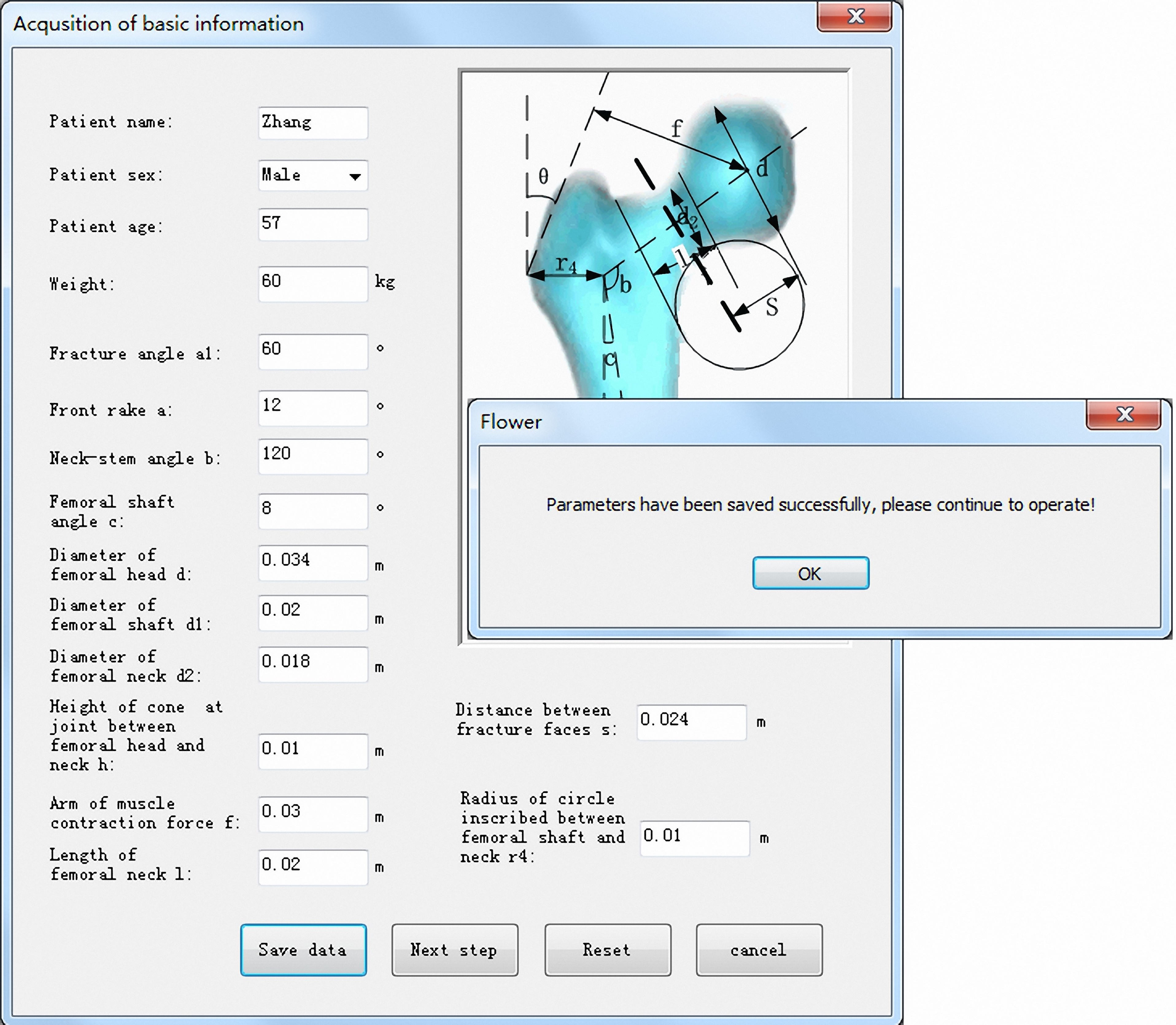
2.2.4Input module of patient basic information
Patient basic information was derived from measurement result of X-ray image. In the parameter information acquisition dialog, edit box was added and variable was introduced for parameters. And eventually, edit box appeared in the program as the form of a variable. The way of adding a variable in the edit box was as follows: select Class Wizard in the View menu, select Member Variable in the Class Wizard content, set Class Name as s class which was defined in the current edit box, select ID corresponding to the edit box, click Add Variable button and input variable name and variable type.
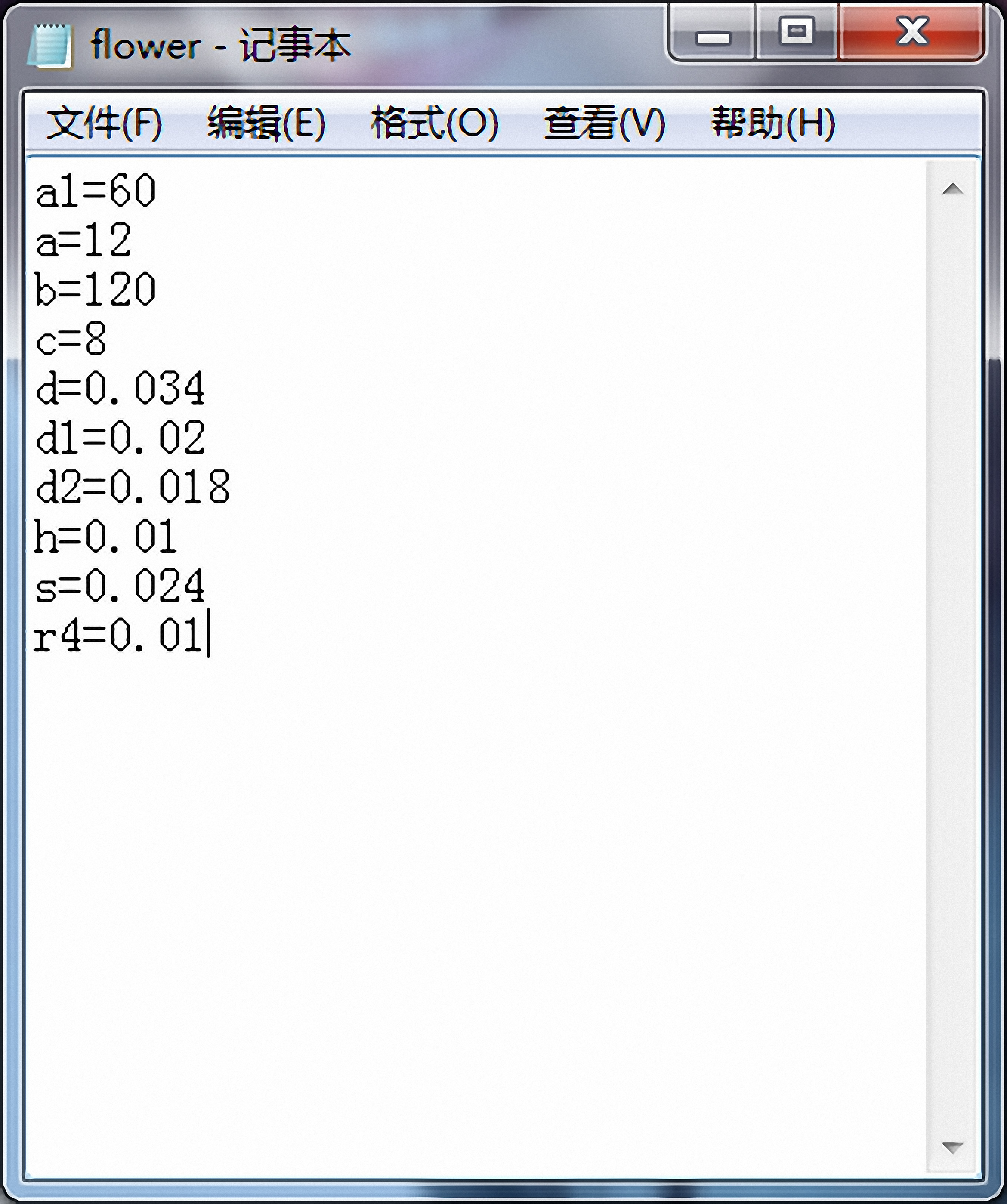
File output was accomplished by ofstream, which was inherited from ostream class and inherited its operations. Therefore, data was written in the file stream by overloading operator
2.2.5Input module of internal fixation mode
In order to combine internal fixation mode with APDL code for femoral neck internal fixation mode, in VC interface design, a radio button was assigned group property, which set single screw, two screws horizontal placement, two screws oblique placement, two screws vertical placement, three screws negative placement and three screws positive placement to a group. When single screw, two screws horizontal placement, two screws oblique placement, two screws vertical placement, three screws negative placement and three screws positive placement were placed in MFC, Group contribution of a radio button needed to be selected. Therefore, users can only select one of these buttons by setting these buttons to a group.
Through adding BN_CLICKED message handling function which was done by selecting “complete selection” button, internal fixation mode and fixed angle are passed to file flower1.
2.2.6Parameter transference between VC++ and APDL
VC++ and APDL nesting process was that the variable in the dialog box made by VC++ was assigned to variable in APDL command stream and read the result of data after the analysis. Variable in VC++ and variable in APDL can not exchange directly. In this study, the parameter variable was written in the flower text, and then read this text in ANSYS APDL language. The parameter variable was assigned to the corresponding variable in APDL code. And the data in flower text was passed to APDL code for parametric femoral neck geometry modeling through input command in APDL. After analysis and calculation in ANSYS background, result data is output in the text and then the data is read by VC. Then the next step was post processing module.
2.3Design of finite element mechanical analysis module
2.3.1Selection of element type and definition of material property
Because femur built was a solid structure with irregular shape, the work used SOLID92 unit [12]. The SOLID92 unit was defined by 10 nodes and each node had 3 degrees of freedom which meant the movement of node coordinates in
Material properties were set to isotropic linear elastic material. Elastic modulus of femur was
Contact mode was set to face to face contact. Femoral surface was set as the contact surface and cylindrical surface was set as target surface. Contact element was CONTA174 and target element was TRGE170 [15].
2.3.2Constraint and load handling
Assuming that when double feet stood still, the gravity of human body was even on both sides of the hip joints. Surface load of individual gravity was applied on the surface of femoral head without considering force generated by surrounding muscle [16]. The lower end of the model was set to a fixed constraint.
2.3.3Solution of internal fixation for femoral neck fracture
The analysis of internal fixation for femoral neck fracture involved contact between screw and femur and contact between fracture faces, which belonged to nonlinear problem. ANSYS solved the nonlinear problem by a series of linear approximation with correction.
The corresponding APDL code of nonlinear solution was as follows:
/SOLU ! Solution module
! Nonlinear solution setting
ANTYPE, 0 ! Static analysis
NROPT, FULL, OFF ! Set the Newton-Raphson option
AUTOTS, ON ! Open auto time step
LNSRCH, ON ! Open linear search
TIME, 1 ! Set solution time
NSUB, 25, 200, 25 ! Define number of solution steps and length of solution step
OUTTRES, ALL, ALL ! Output data of all substep
The main function of finite element analysis dialog was to accomplish analysis of ANSYS software background. The detailed code of message handling function for saving button was as followed:
void CAnsys::OnButton5()
{
UpdateData(true); // update variable related to edit box
ofstream outfile;
// additional form output
outfile.open(“F
outfile.seekp(0, ios::beg);
outfile
MessageBox(“Parameter has been saved successfully, please continue to operate!”);
}
The main function of “Save data” button in finite element analysis dialog was to transfer internal fixation mode and angle to means text and stored in an additional way. Because in results optimization dialog, when the function read different internal fixation mode and fixation angle in means text, data space was set as an identifier to read data. Therefore, in this function, data storage was output as the form of space. Although in selection of internal fixation mode, internal fixation mode had already stored in flower1 file, internal fixation mode and its angle would be cleared each time, which meant when select another internal fixation mode and angle, the ones stored before would be cleared and only displayed the current option. In this way, the right fixation mode in APDL file of femoral neck fracture would be accomplished. Some software such as ANSYS is not the ones especially for mechanical analysis of femoral neck fracture and they have a higher demand for doctors.
Figure 1.
Acquisition of patient information.
2.4Design of post processing module
2.4.1Acquisition of ANSYS analysis results
In the finite element analysis dialog, click “Next step” button and ANSYS analysis results would be shown. The main function of this dialog was to display ANSYS post processing results in the dialog, such as the cloud of total displacement US, the cloud of lateral displacement UX, the cloud of fracture displacement DS and the cloud of screw stress. Then the cloud data was written in the corresponding edit box. The data was stored in flower2 text through clicking “Save data” button. For the generation of ANSYS batch images, in order to gain a better display, program turned ANSYS default generation into display form of white background color image.
2.4.2Optimization of ANSYS batch results
In the ANSYS analysis results dialog, click “Next step” button and results display and optimization would be shown. Add message handling function for “Fixation mode display” button and display the internal fixation mode in the dialog. Click the button and judge that whether means text existed. If it did not exist, there would be a message dialog which alert that the data of internal fixation mode did not exist and needed to be stored firstly. If it existed, the internal fixation mode in the text would be display in the dialog. In order to achieve this function, the programming ideas were as follows. The data in the text was read by set space as an identifier and written in the character string. Then these data would be shown in the dialog through the function SetWindowText in MFC [17]. In finite element analysis dialog, the data of selected internal fixation mode and fixation angle was stored in the means text. In the ANSYS analysis results dialog, results of different internal fixation mode and fixation angle were stored in flower2 text. The main function of results display and optimization was to display selected internal fixation mode and ANSYS batch results of corresponding internal fixation mode in the dialog. And according to the evaluation criteria, the analysis results were optimized.
2.4.3Evaluation criteria setting
(1) Stability of the whole structure. In the case of double feet standing, femoral head would be subjected to a load and produce displacement which included lateral displacement UX in
(2) Max fracture displacement between fracture surfaces. It was considered that the proximal femur was a structure similar to that of a cantilever beam. Upper end of the femoral neck suffers tensile stress and its lower end suffers compressive stress under the action of the load. And therefore, a certain amount of fracture displacement was generated between fracture surfaces.
(3) Max stress of fastening screw. Under the same load, the smaller the max stress of fastening screw was, the stronger the bearing capacity of screw was.
Figure 2.
Storage of patient information.
3.Results and discussion
Patient weight was 60 kg. Fracture angle was 60
According to the patient measured fracture angle, the doctor chose an internal fixation mode at first, such as single screw mode, fixation angle 60
Figure 3.
Selection interface for internal fixation mode and finite element analysis interface.
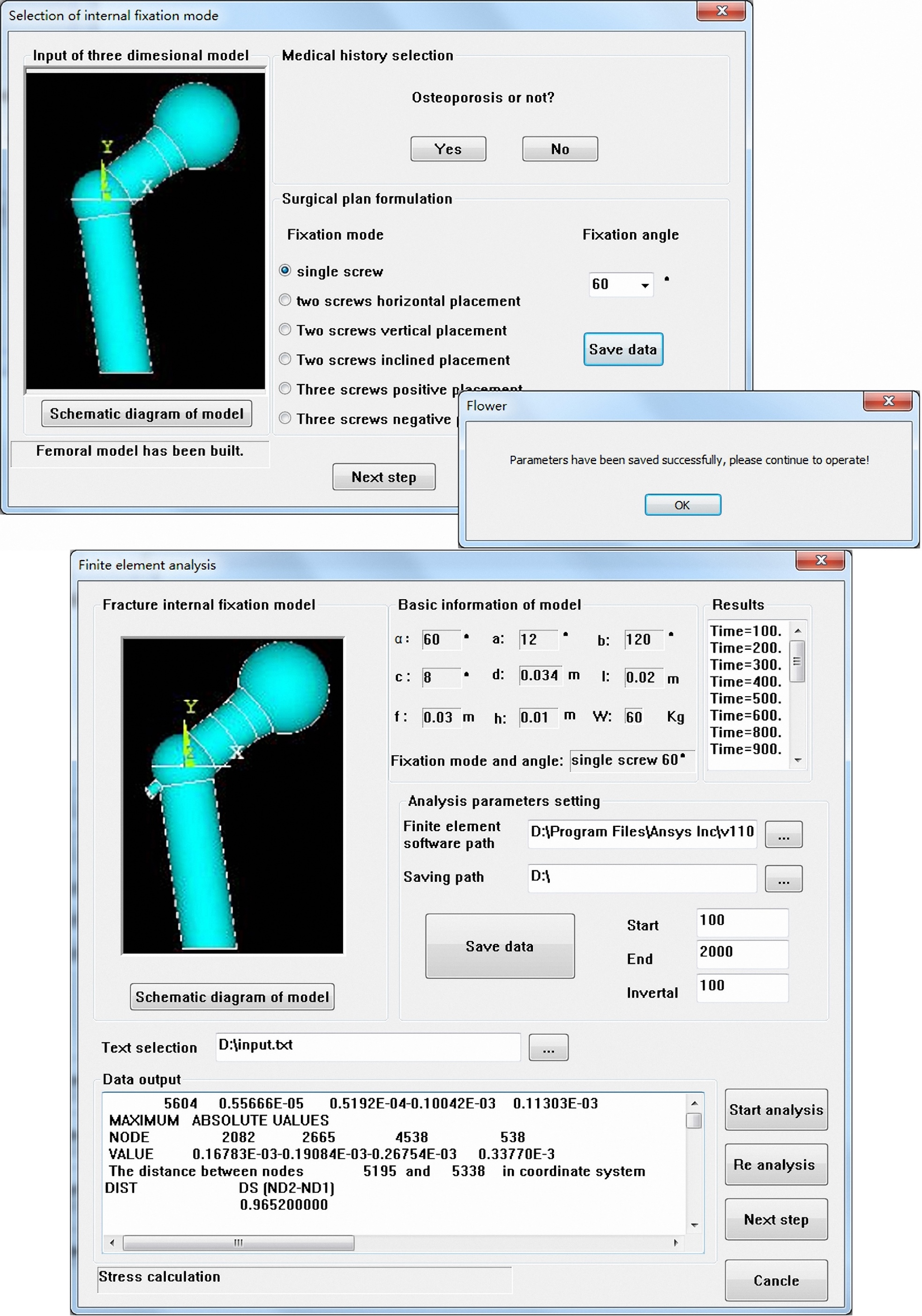
Figure 4.
Results storage of ANSYS analysis.
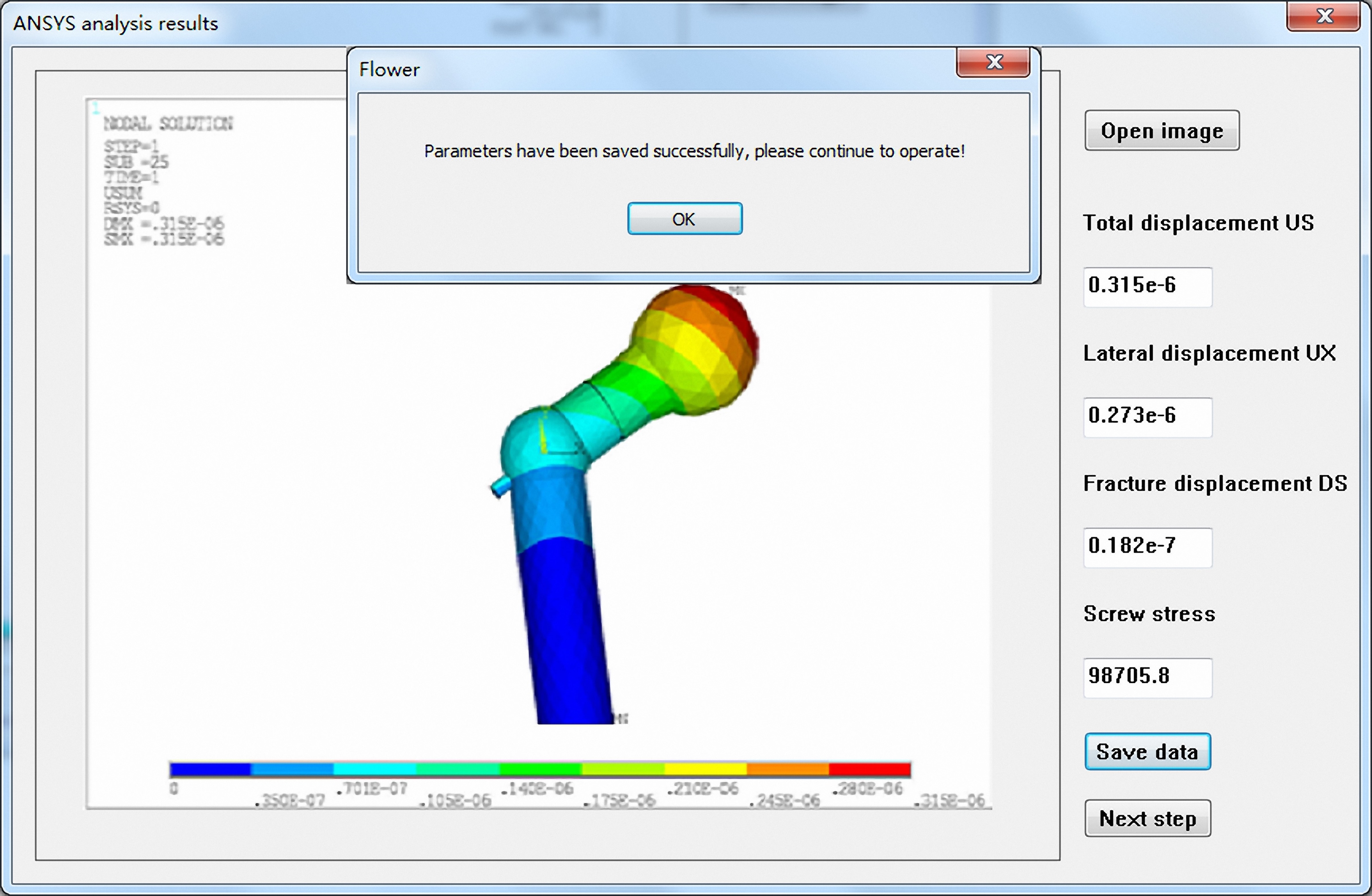
Figure 5.
Storage of internal fixation mode.
Figure 6.
Storage of analysis results.
Figure 7.
Results optimization.
Click “Start analysis” button, ANSYS batch processing finite element analysis was initiated by calling ANSYS software background. Click “Re analysis” button, interface would go back to the internal fixation mode dialog and chose internal fixation style again. This operation chose two screws vertical placement with fixation angle 60
Through reading the cloud generated by batch processing, finite element analysis data was gained, which included: the total displacement US of femur, lateral displacement UX of femoral head, max fracture displacement DS between fracture faces and max stress of screw. Write these data in the edit box and save them in flower2 text, which prepared for the display and data processing lately. As shown in Fig. 4.
When in “Results display and optimization” module, click “Fixation mode display” button and the fixation mode that was stored in means text before would be shown in the interface. Click “Results display” button, data results of different fixation mode in the flower2 would be shown in the interface. When click “US and DS optimization”, the system would sort US and DS automatically and output the best results. Users can also choose the best internal fixation mode by comprehensive consideration between total displacement US, lateral displacement UX, fracture displacement DS and screw stress. Figure 5 represented the internal fixation mode stored in means text. Figure 6 represented results data of batch processing for the different internal fixation mode. As shown in Fig. 7, when click “Fixation mode display” button, the system would read the internal fixation mode in means text and displayed it; when click “Results display” button, analysis results stored in flower2 text will be read and displayed; when click “US and DS optimization” button, optimization operation of US and DS would begin.
4.Conclusion
The work designed a set of computer assisted optimal system for treatment of femoral neck fracture. The system can offer directly the mechanical analysis results of internal fixation mode of femoral neck fracture and provide an optimized fixation plan. The system is easy to operate, strong pertinence and has a low requirement for computer skills. The software used the module design plan and has a good capacity of expansion. In the process of software system design, following problems have been solved, which includes: problems about parametric modeling of bone, fracture face and fixation mode; problems about the parameter transmission between VC++ and APDL; problems about the modeling of process of mechanical analysis for fracture internal fixation mode using finite element method; problems about results display of batch processing, optimization criterion setting and optimization of analysis results. Through the design of preprocessing module, finite element mechanical analysis module and post processing module, the whole optimization process is accomplished. The computer assisted optimal system for treatment of femoral neck fracture offers a new effective way for design of computer assisted medical software through the call between VC++ and APDL and the simple presentation for users by sealing the complex process of finite element analysis.
Acknowledgments
This research was supported by NSFC (No. 61572159), NCET (NCET-13-0756), Distinguished Young Scientists Funds of Heilongjiang Province (JC201302) and Chang Jiang Scholar Candidates Program for Provincial Universities in Heilongjiang (2013CJHB007).
Conflict of interest
None to report.
References
[1] | Wang WD, Zhang P, Shi YK, Jiang QQ, Zou YJ. Design and compatibility evaluation of magnetic resonance imaging-guided needle insertion system. J Med Imaging and Health Infor (2015) ; 5: (8): 1963-1967. |
[2] | Li M, Wang H. Analysis of 15 cases of femoral neck fracture in young adults treated with hollow compression screw fixation. Jilin Med J (2010) ; 31: (25): 4354-4354. |
[3] | Looker AC. Femur neck bone mineral density and fracture risk by age, sex and race or Hispanic origin in older US adults from NHANES III. Arch Osteoporos (2013) ; 8: (1-2): 1-11. |
[4] | Chapuis J, Schramm A, Papas I, Hallermann W, et al. A new system for computer-aided preoperative planning and intraoperative navigation during corrective jaw surgery. IEEE T Inf Technol B (2014) ; 11: (3): 274-287. |
[5] | Zhao WP, Lin F, Lu QP. Three dimensional construction and finite element analysis to predict the collapse of femoral head. Chinese Journal of Biomedical Engineering (2005) ; 24: (6): 784-78. |
[6] | Keyak JH, Rossi SA. Prediction of femoral fracture load using finite element models: An examination of stress and strain based failure theories. J Biomech (2000) ; 33: (2): 209-14. |
[7] | Cody DD, Gross GJ, Hou FJ. Femoral strength is better predicted by finite element models than QCT and DXA. J Biomech (2009) ; 32: (10): 1013-20. |
[8] | Ota T, Yamamoto I, Morita R. Fracture simulation of the femoral bone using the finite-element method. J Bone Miner Metab (2012) ; 17: (2): 1008-12. |
[9] | Wang MN, Guo HS. Fixation for femoral neck fracture based on nonlinear materials. Journal of Medical Biomechanics (2012) ; 27: (2): 152-158. |
[10] | Zhou N, et al. Advanced engineering application examples of APDL ANSYS and two development. Beijing: China Water Conservancy and Hydropower Publishing House (2007) ; 369-370. |
[11] | ANSYSInc., ANSYS Programmer’s Manual, USA ANSYS Inc 2013. |
[12] | Gong SG. ANSYS operation command and parametric programming. Beijing: Machinery Industry Press (2004) ; 106-121. |
[13] | Xu RJ, Li DC, Sun ML. Finite element analysis of single screw internal fixation for femoral neck fracture. Journal of Medical Biomechanics (2004) ; 19: (2): 88-92. |
[14] | Xu RJ, Li DC, Sun ML. Biomechanical study of different internal fixation for adductive femoral neck fractures. Beijing Biomedical Engineering (2005) ; 24: (3): 220-221. |
[15] | APDL user guide of American ANSYS company. USA ANSYS Inc (2012) . |
[16] | Meng L. Three dimensional reconstruction and biomechanical analysis of internal fixation model of femoral neck fracture. Wuhan: Hua Zhong University of Science and Technology (2013) ; 13-50. |
[17] | Kiapour AM, Kaul V, Kiapour A, Quatman, CE, Wordeman SC, Hewett TE. The effect of ligament modeling technique on knee joint kinematics: A finite element study. Applied Mathematics (2014) ; 4: (5A): 91. |


