
Optimization of a passively suspended injection impeller for Left ventricular assist device
Abstract
BACKGROUND:
A rotary blood pump with a passively levitated impeller and a large bearing gap between housing and impeller in the range of 0.6 mm has been developed for Left ventricular assist device (LVAD).
OBJECTIVE:
The purpose of the present study is to determine the optimal injection angle of the impeller to improve its radial stability by increasing the radial suspension force.
MTEHODS:
Since the radial and axial suspension forces generated by an injection channel were equal, the axial suspension force obtained from numerical simulation was chosen as the evaluation parameter. First, the impellers with different injection angles were calculated with numerical simulation to obtain the maximum axial suspension force. Second, the radial motion of the impeller was experimentally measured for the evaluation of the radial stability.
RESULTS:
The numerical analysis revealed that the axial suspension force acting on the impeller reached the maximum value at the injection angle of 60 degrees. In the measurement test, the impeller with injection angle of 60 degrees achieved the most stable radial movement. Therefore, the effectiveness of the numerical analysis was validated.
CONCLUSIONS:
The injection angle of impeller could be optimized to improve its radial stability, and the optimal injection angle was 60 degrees.
1.Introduction
Various types of implantable Left ventricular assist devices (LVADs) have been applied in the treatment of end-stage heart failure [1, 2, 3, 4, 5, 6, 7, 8, 9, 10]. Currently, the third-generation blood pumps with noncontact bearings, such as magnetic or hydrodynamic bearings, have been developed to improve the durability of the devices. A blood pump with a magnetic bearing levitates the impeller using magnetic force generated by a controllable electromagnet, which requires displacement sensors and complex control systems [11, 12, 13]. In contrast, a blood pump with a hydrodynamic bearing levitates the impeller using the localized high pressure generated either by the grooves or the tapered blade surfaces based on lubrication theory [14, 15]. As the hydrodynamic bearing is a passive bearing, the blood pump has high reliability since additional displacement sensors or control components are not required. However, present blood pumps with hydrodynamic bearings require very small gaps between the impeller and the housing, resulting in high manufacturing cost and shear stress. We previously developed a rotary blood pump with a passively levitated impeller and a large bearing gap between the housing and the impeller in the range of 0.6 mm [16]. The impeller was levitated by the force generated by the injection flow. The large bearing gap was beneficial to reduce the shear stress and the cost of the device. The axial movement of the impeller was measured quantitatively, while the radial suspension of impeller was evaluated qualitatively in the previous work. In addition, the radial motion of the impeller depends on the radial suspension force, centrifugal force, radial magnetic force, and radial hydraulic force. As the radial suspension force provides the only positive stiffness to suspend the impeller, it is a critical factor to affect the radial stability.
The purpose of the present study is to determine the optimal injection angle of the impeller to improve its radial stability by increasing the radial suspension force. As the radial and axial suspension forces generated by the single injection channel were equal, the axial suspension force was chosen as the evaluation parameter. First, the impellers with different injection angles were numerically calculated with a focus on enlarging the axial suspension force. Second, the radial motion of impeller was experimentally measured with laser displacement sensors to verify the effectiveness of numerical analysis.
Figure 1.
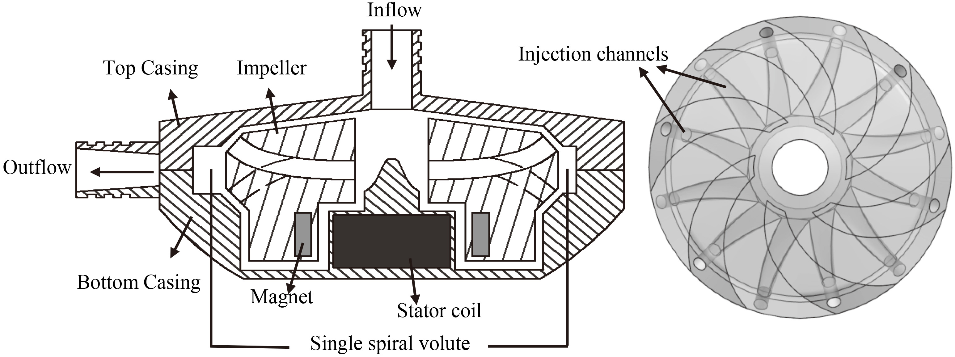
Structure of the developed centrifugal blood pump and impeller.
2.Materials and methods
2.1LVAD with a passively suspended impeller
Figure 1 illustrates the developed rotary blood pump with a passively suspended impeller. The diameter of the pump casing is 80 mm, and its height is 27 mm. The total axial or radial gap between the impeller and the casing is 0.6 mm. The Neodymium Iron Boron permanent magnets are sealed in the impeller, and the stator coils are placed in the pump casing. The impeller is driven through the electromagnetic interaction between the magnets and the coils. The semi-open impeller has twelve injection channels. The outlets of six injection channels are distributed on the blades while the other six outlets are placed on the lower sloping surface of impeller. When the impeller rotates, the blood is forced to accelerate along the channels and injected into the gaps between the impeller and the casing, which produces localized high pressure to generate the suspension force. Since the angles of acting surfaces are 45 degrees, the radial and axial suspension forces generated by the single injection channel are equal.
Figure 2.
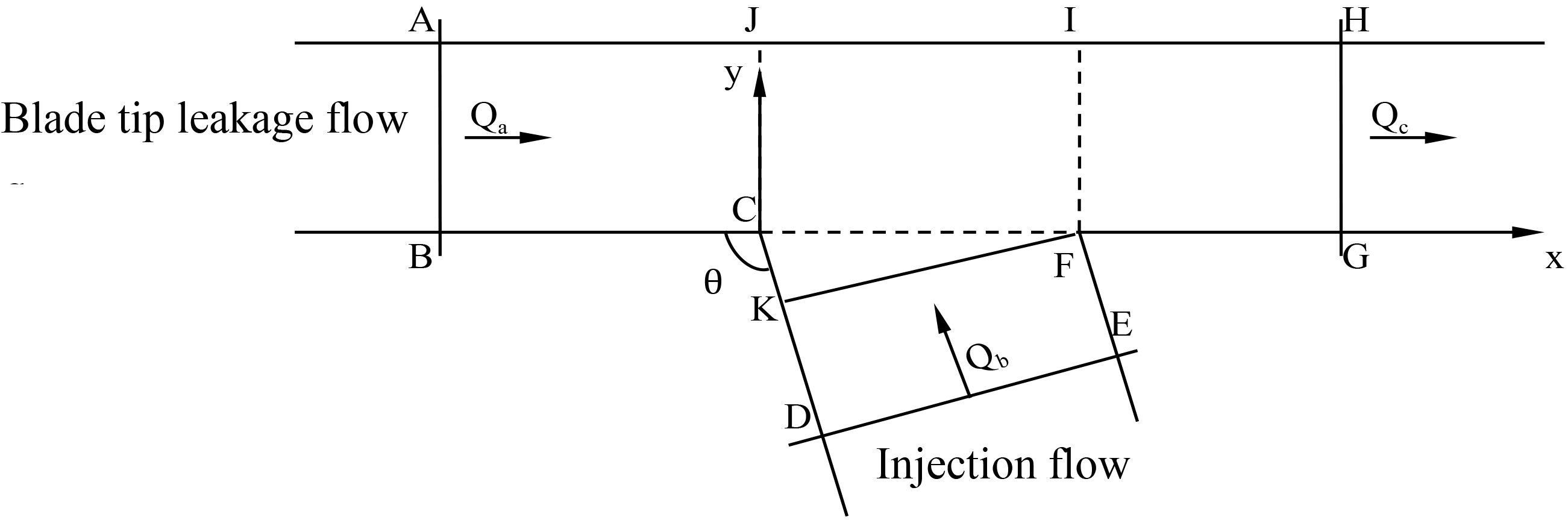
Two-dimensional analysis of region around the outlet of injection channel.
2.2Computational fluid dynamics analysis
Figure 2 shows the 2D analysis of the region around the outlet of injection channel. The flow from the injection channel converges into the blade tip leakage flow. The momentum equation in the x direction for control volume ABCDEFGHA can be written as follows:
(1)
where
According to the Eq. (1),
Numerical analysis with computational fluid dynamics (CFD) was employed to investigate the injection angle of the impeller. As the radial and axial suspension forces generated by the single injection channel were equal, the axial suspension force was chosen ashe evaluation parameter. The computational mesh was generated by the software package Hypermesh (Altair, Inc., USA), and the Fluent 15.0 (Ansys, Inc., USA) was applied to perform the numerical analysis. The motion of the impeller was incorporated using the multiple reference frame (MRF) approach. The rotation speed of impeller was set to 2000 rpm. No-slip boundary conditions were applied to the walls. The working fluid was assumed to be blood with a density of 1055 kg/m
Considering the constraint of the impeller structure, the injection angle was increased from 30 to 150 degrees in increments of 10 degrees. Impellers with injection angles of 60
Figure 3.
Impellers with different injection angles. (a) 60 degrees. (b) 90 degrees. (c) 120 degrees.
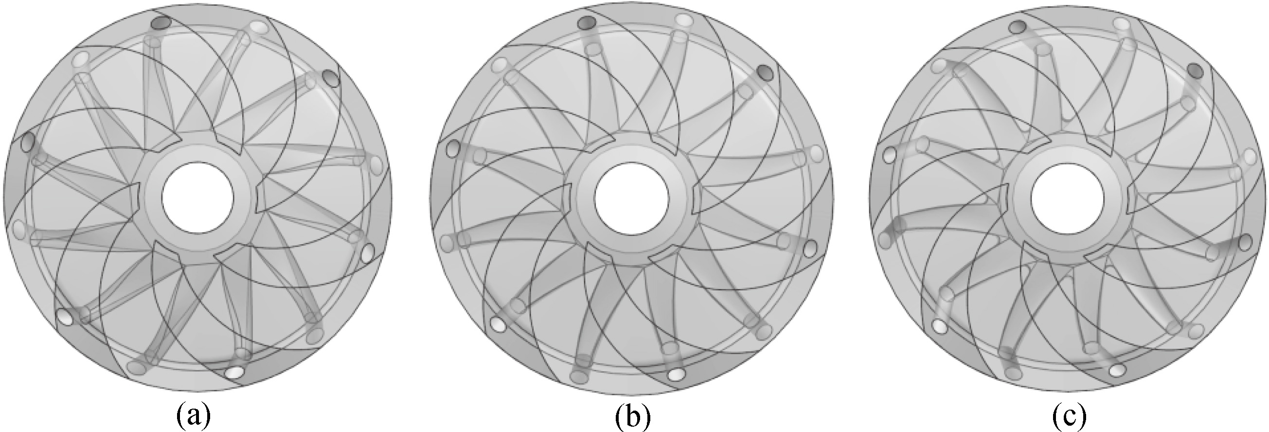
Figure 4.
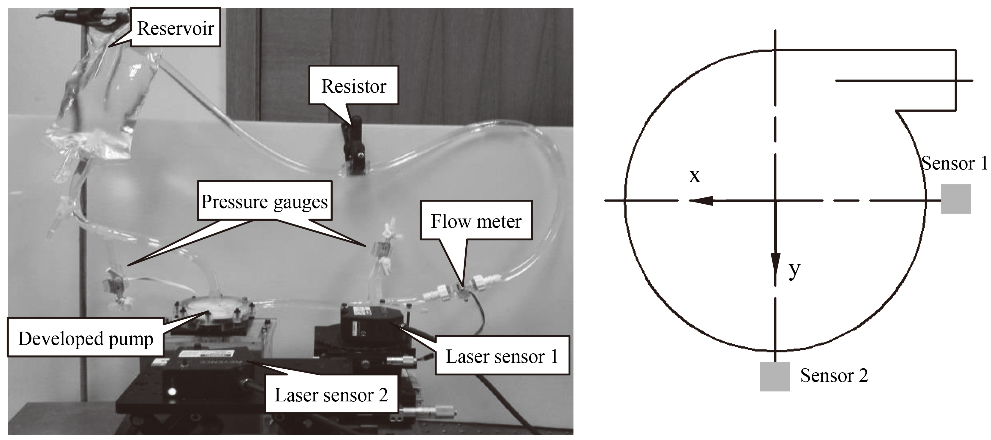
Measurement system for measuring the impeller trajectory using two laser displacement sensors.
2.3Measurement of impeller radial trajectory
A mock circulation loop was used to measure the radial motion of impeller in order to evaluate its radial stability, as shown in Fig. 4. It consisted of the developed blood pump, two laser displacement sensors (LK-G150, Keyence, Japan), two pressure gauges (MX9505T, Smiths Medical ASD Inc., Dublin, USA), a turbine flow meter (YF-S201C, China), an adjustable resistor and a soft reservoir bag. Two laser displacement sensors were located on the radial direction of the pump. The localized surface of the casing was thinned, which enabled the laser displacement sensors to measure the radial motion of the impeller. A 33% glycerin water solution with the same viscosity at the room temperature as 37
The working conditions were set to a pressure head of 100 mmHg and a flow rate of 5 L/min. The measured data of laser displacement sensors were synchronously recorded on a PC with 10 kHz sampling frequency and 1 s sampling time. The mean position and radius of the orbit were calculated to describe the radial motion of impeller. The mean position was the gravity center of the orbits, and the mean radius was the mean distance between the mean position and each point on the orbits.
3.Results
Figure 5a shows the numerically obtained axial force versus injection angle when the bearing gaps were set to 0.15 mm and 0.3 mm. The axial force increased corresponding to the reduction of the axial bearing gap, which indicated that the injection flow was effective to produce the suspension force. Figure 5b shows the residual axial suspension force versus the injection angle. When the bearing gap changed from 0.15 mm to 0.3 mm, the residual axial suspension force had a maximum value at the injection angle of 60 degrees.
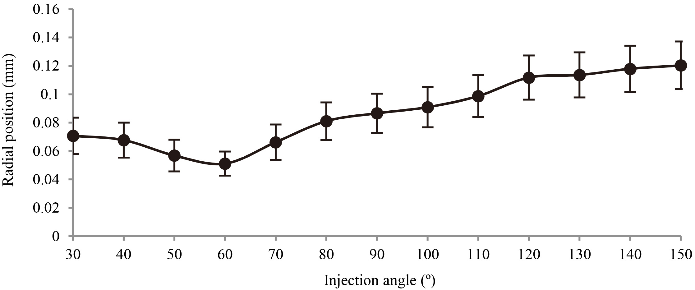
Figure 6 shows the mean impeller positions and radii of the orbit for the impellers with different injection angles. The solid circle indicates the mean impeller position, and the bar represents the radius of orbit. It was observed that the mean impeller position and the radius of orbit had a minimum value when the injection angle of impeller was 60 degrees. The measured orbital radius of the optimal model was 8.5
Table 1
Injection angles of the selected models
| Model number | 1 | 2 | 3 | 4 |
| Injection angle | 30 | 60 | 90 | 150 |
Figure 5.
(a) Numerically obtained axial force acting on the impeller when the bearing gaps were set to 0.15 mm and 0.3 mm. (b) Residual axial suspension force versus the injection angle.
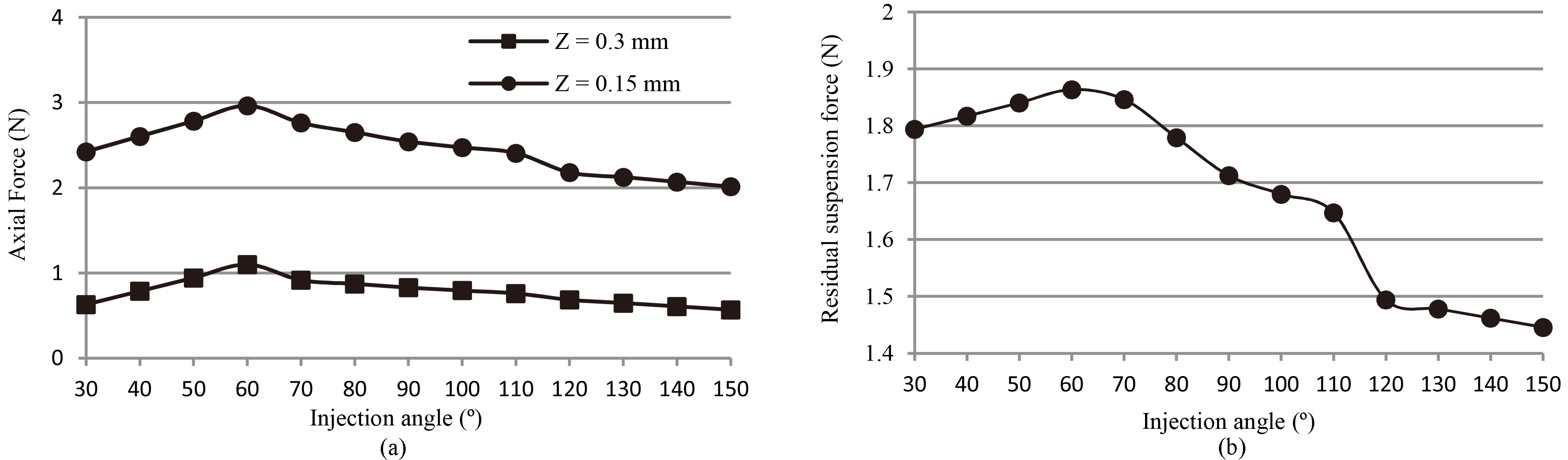
Figure 6.
Mean impeller position and radius of the orbit versus the injection angle.
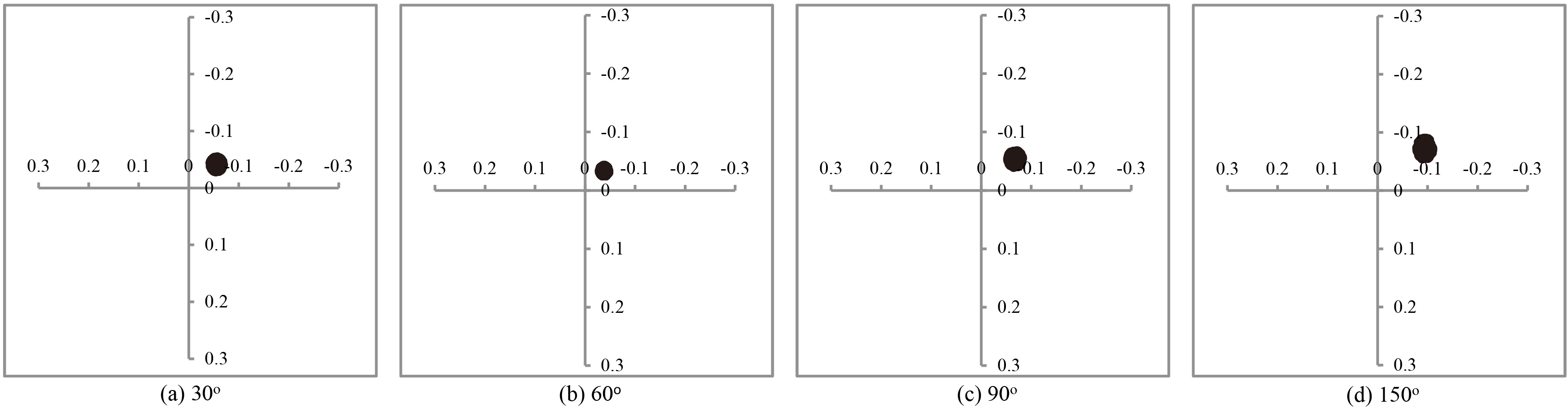
Four typical models were chosen to indicate the radial motion of impeller, as shown in Table 1 . The injection angles of the four impellers were 30
4.Discussion
From Eq. (1), the maximum suspension force was achieved when the injection angle was 30 degrees. Based on the results of numerical simulation, the maximum suspension force was obtained when the injection angle was 60 degrees. This inconsistency might be caused by the simplification of 2D analysis, which neglected the complicated flow pattern around the injection area in the practical situation. However, the 2D analysis was still an effective approach to provide foundation to optimize the injection angle of impeller.
After the optimization of the impeller, the maximum residual axial suspension force was about 1.86 N, an increase of about 60 percent comparing to previous research. The radial suspension force increased along with the increase of the axial suspension force. As the radial suspension force provides positive stiffness to suspend the impeller, the higher suspension force contributes to the improvement of radial stability of impeller. Although the radial stability of previous impeller was not evaluated quantitatively, the radial stability of optimal impeller was obviously superior to that of previous model. In addition, the most stable radial motion of impeller was experimentally obtained when the injection angle of impeller was 60 degrees, which was consistent with the result of numerical analysis. Therefore, the effectiveness of the numerical analysis was validated.
Figure 7 indicates the impeller moving toward the cutwater of the pump. The reason was that the velocity decreased as the fluid diffused from the cutwater into the outlet. Based on the Bernoulli equation, the reduction in pressure would occur when the fluid speed increases. Hence, low pressure around the cutwater produced a low pressure force. As a result, a net radial hydraulic force pointed towards the cutwater, which was a typical phenomenon for centrifugal pumps [17].
Figure 7.
Impeller trajectories for the model 1, 2, 3, and 4.
For a blood pump with a noncontact bearing, the radial stability of the impeller was a critical factor to affect the hemolysis [18]. When the radial motion of the impeller was in the stable mode, it was beneficial to reduce the shearing stress and the hemolysis. The hemolysis test of the prototype will be conducted in the future.
5.Conclusions
In this study, the injection angle of impeller was numerically investigated and experimentally evaluated to improve radial stability. According to the results of numerical analysis, the impeller with injection angle of 60 degrees generated the maximum radial suspension force. Through the results of radial motion measurement test, the impeller with injection angle of 60 degrees had the most stable radial motion, which verified the effectiveness of numerical analysis. In conclusion, the injection angle of impeller could be optimized to improve its radial stability.
Conflict of interest
None to report.
Acknowledgments
The present study was supported by the Shanghai Committee of Science and Technology, China (Grant No. 15441905200), National Natural Science Foundation of China (50821003), and the foundation from the State Key Laboratory of Mechanical Systems and Vibration (MSVZD201203).
References
[1] | Griffith BP, Kormos RL, Borovetz HS, et al. HeartMate II left ventricular assist system: from concept to first clinical use. The Annals of Thoracic Surgery. (2001) ; 71: (3): S116-S120. DOI: http//dx.doi.org/10.1016/S0003-4975:(00)02639-4 |
[2] | Nojiri C, Kijima T, Maekawa J, et al. Development Status of Terumo Implantable Left Ventricular Assist System. Artificial Organs. (2001) ; 25: (5): 411-413. DOI: 101046/j.1525-1594.2001.025005411.x |
[3] | Griffith K, Jenkins E, Pagani FD. First American experience with the Terumo Dura Heart left ventricular assist system. Perfusion. (2009) ; 24: (2): 91-92. DOI: 101177/0267659109106826 |
[4] | Kirklin JK, Naftel DC, Kormos RL, et al. Second Intermacs Annual Report: More Than 1000 Primary LVAD Implants. Journal of Heart & Lung Transplantation the Official Publication of the International Society for Heart Transplantation. (2010) ; 29: (1): 1-10. DOI: 101016/j.healun.2009.10.009 |
[5] | Schmid C, Tjan TDT, Etz C, et al. First clinical experience with the incor left ventricular assist device. Journal of Heart & Lung Transplantation. (2005) ; 24: (9): 1188-1194. DOI: 101016/j.healun.2004.08.024 |
[6] | Bearnson GB, Jacobs GJ, Khanwilkar PS, et al. Heart Quest Ventricular Assist Device Magnetically Levitated Centrifugal Blood Pump. Artificial Organs. (2006) ; 30: (5): 339-346. DOI: 101111/j.1525-1594.2006.00223.x |
[7] | Yamazaki K, Saito S, Tomioka H, et al. Next Generation LVAD “EVAHEART”: Current Status of Japanese Clinical Trial. Journal of Cardiac Failure. (2006) ; 12: (8): S158. DOI: 101016/j.cardfail.2006.08.074 |
[8] | Farrar DJ, Bourque K, Dague CP, et al. Design features, developmental status, and experimental results with the Heartmate III centrifugal left ventricular assist system with a magnetically levitated rotor. ASAIO Journal. (2007) ; 53: (3): 310-315. DOI: 101097/MAT.0b013e3180536694 |
[9] | Esmore D, Kaye D, Spratt P, et al. A prospective, multicenter trial of the VentrAssist left ventricular assist device for bridge to transplant: safety and efficacy. Journal of Heart & Lung Transplantation the Official Publication of the International Society for Heart Transplantation. (2008) ; 27: (6): 579-588. DOI: 101016/j.healun.2008.02.012 |
[10] | Gazzoli F, Alloni A, Pagani F, et al. Arrow CorAide left ventricular assist system: initial experience of the cardio-thoracic surgery center in Pavia. The Annals of Thoracic Surgery. (2007) ; 83: (1): 279-282. DOI: 101016/j.athoracsur.2006.05.026 |
[11] | Asama J, Shinshi T, Hoshi H, et al. Dynamic characteristics of a magnetically levitated impeller in a centrifugal blood pump. Artificial Organs. (2007) ; 31: (4): 301-311. DOI: 101111/j.1525-1594.2007.00378.x |
[12] | Chen C, Paden B, Antaki J, et al. A Magnetic Suspension Theory and Its Application to the HeartQuest Ventricular Assist Device. Artificial Organs. (2002) ; 26: (11): 947-951. DOI: 101046/j.1525-1594.2002.07125.x |
[13] | Onuma H, Murakami M, Masuzawa T. Novel maglev pump with a combined magnetic bearing. Asaio Journal. (2005) ; 51: (1): 50-55. DOI: 101097/01.MAT.0000151149.23519.19 |
[14] | Kosaka R, Maruyama O, Nishida M, et al. Improvement of Hemocompatibility in Centrifugal Blood Pump With Hydrodynamic Bearings and Semi-open Impeller: In Vitro Evaluation. Artificial Organs. (2009) ; 33: (10): 798-804. DOI: 101111/j.1525-1594.2009.00817.x |
[15] | Watterson PA, Woodard JC, Ramsden VS, et al. VentrAssist hydrodynamically suspended, open, centrifugal blood pump. Artificial Organs. (2000) ; 24: (6): 475-477. DOI: 101046/j.1525-1594.2000.06606.x |
[16] | Zhu L, Wu Y, Luo Y. Experimental evaluation of a Novel Injection Suspended Impeller for Implantable Centrifugal Blood Pump. International Journal of Applied Electromagnetics and Mechanics. Forthcoming (2016) . |
[17] | Japikse D, Marscher W, Furst R. Centrifugal Pump Design and Performance. Concepts ETI, Inc., (1997) . |
[18] | Kataoka H, Kimura Y, Fujita H, et al. Influence of radial clearance and rotor motion to hemolysis in a journal bearing of a centrifugal blood pump. Artificial Organs. (2006) ; 30: (11): 841-854. DOI: 101111/j.1525-1594.2006.00311.x |


