
Biomechanical design of escalading lower limb exoskeleton with novel linkage joints
Abstract
In this paper, an obstacle-surmounting-enabled lower limb exoskeleton with novel linkage joints that perfectly mimicked human motions was proposed. Currently, most lower exoskeletons that use linear actuators have a direct connection between the wearer and the controlled part. Compared to the existing joints, the novel linkage joint not only fitted better into compact chasis, but also provided greater torque when the joint was at a large bend angle. As a result, it extended the angle range of joint peak torque output. With any given power, torque was prioritized over rotational speed, because instead of rotational speed, sufficiency of torque is the premise for most joint actions. With insufficient torque, the exoskeleton will be a burden instead of enhancement to its wearer. With optimized distribution of torque among the joints, the novel linkage method may contribute to easier exoskeleton movements.
1.Introduction
In recent years, the greying populace, growing need for medical rehabilitation, and seemingly more frequent geological disasters have hand in hand put forth ever more heated demands in the field of robotics. With emerging inspiration for industrial advancement, much attention has been paid to powered robotic enhancements which help people walk or carry heavy payloads. And with the intimacy between human body and the machine, exoskeleton robots have become a development trend.
The study of exoskeleton robots began in the 1960s when the development of sensory and driving technologies and advancements in energy production and retention promoted the study of exoskeleton robots. Their development in Berkeley, California was impressive, from the first-generation BLEEX to the ExoHiker to the third-generation HULC [1, 2, 3]. With the use of hydraulic drivers, the weight loading ability rose to 45 kg [4]. Now, this kind of production is used in militaries across the globe. The XOS-2, which is driven by hydromantic, was produced in 2010 by Raytheon near the area where the first exoskeletons were invented. This new version can lift up to 90.7 kg [5]. In addition to military applications, exoskeleton robots have also been used in rehabilitation training of both the elderly and the young. The HAL series, designed at the University of Tsukuba, is in its 5
In addition to cope with basic human body movements, the ability to maintain high torque at relatively large bending angle was also taken into account so that these joints may allow obstacle-surmounting maneuvers. Most exoskeleton robots that adopt a linear drive connect the wearer directly to the controlled part [7]. This is easy to achieve, but the active drive element, namely the hydraulic cylinder, moves with the controlled part, making it difficult to fit into a compact design and causing problems in the improvement of peak torque. In this study, a lower limb escalading exoskeleton with novel linkage joints based on human anatomy was developed. A compact layout was achieved by changing the design of the links, and the joint was given greater torque for delivering power at bigger angles.
2.Exoskeleton design
2.1The distribution of DOF
In order to guarantee both comfort and security to the human body, a reasonable amount of freedom is needed. Although the proposed exoskeleton robot was nearly anthropomorphic, it didn’t need to have the same range of motion of the human body. This was because the parallel hinge was formed to vary the degree of freedom. Extra flexibility can increase the load on a passive hinge and can result in unexpected vibrations and uneven barycenter, which can cause the wearer discomfort and even danger.
Table 1
Movement range of each DOF
| Degrees of freedom | Movement range | Design range |
|---|---|---|
| Hip flexion/extension | 145 | 120 |
| Hip abduction/adduction | 25 | 25 |
| Hip internal/external rotation | 40 | 20 |
| Knee flexion/extension | 135 | 120 |
| Ankle flexion/extension | 85 | 45 |
| Ankle abduction/adduction | 35 | 10 |
Figure 1.
Overall structure.
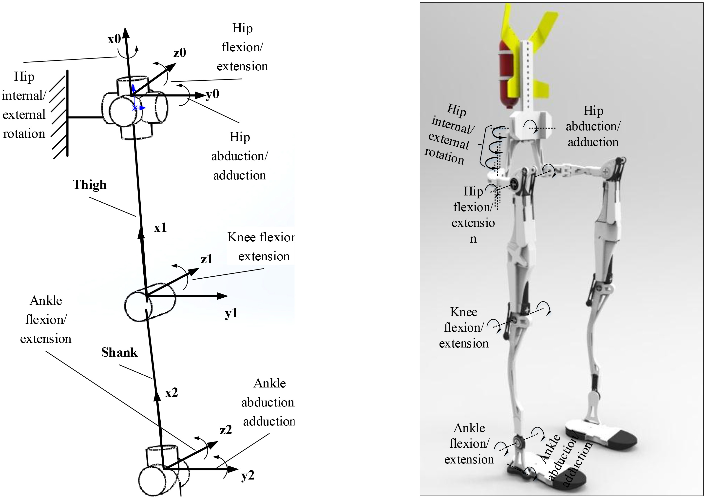
Considering the movement angle and distribution to the degree of freedom of the body, Fig. 1 illustrates the overall structure. The lower limb exoskeleton degree of freedom and range of motion are shown in Table 1 [8].
A 3-DOF design was used in the hip joint. Hip flexion/extension passes through the body’s axis directly, and because it is main degree of freedom in a motion, it needs to closely mimic human movement. The hips’ internal/external rotation was mainly arranged for turning during walking, and due to the formation of the hinge degrees of freedom being in a horizontal layout, it didn’t receive the torque in the direction of gravity. Therefore, the arrangement utilized the multiple hinges mode, and allowed the center of rotation move with the human body’s hip rotation axis at any time. The hip adduction/abduction required an eccentric design, and the rotation degree of freedom was placed on the waist. Because this degree of freedom bears the main torque from the direction of gravity, it only had a small amplitude in basic movements. If it was designed with a double hinge structure, it would agree with human body movements perfectly, but it may also cause an unsteady center of gravity and other problems. Here, the design was simplified into a single hinge structure.
A 1-DOF design was used in the knee. The structure was equipped with a mechanical limiter so that when the wearer stretches to a vertical position, the movement range cannot go beyond the scope of what the human body can bear. A 2-DOF design was used in the ankle joint. Ankle flexion/extension passes through the ankle axis, and because it is a major movement link, it needs to cooperate smoothly with the human body. Ankle adduction/abduction is not a dominant factor for body movement, which was why the corresponding mechanism was installed under pelma. Another benefit of such setting was improved reliability of overall weight distribution.
2.2Power source arrangement
The primary purpose of the escalading exoskeleton was to navigate through complex terrain; therefore, it needed a lightweight actuator, higher gear ratio, and compactness. For the power source, this paper selected a hydraulic cylinder as the actuator. With respect to the motor, a hydraulic cylinder is more lightweight and compact, and can provide a great gear ratio. To match the power curve of the human body while walking on a level surface, a 20 mm two-way linear cylinder with 7 Mpa and 15 L total flux was chosen.
When selecting the active joints, referencing the basic form of body movement while walking on level ground, stairs, and slopes, and taking into account the overall mass and inertia, the design chose hip flexion main output/extension, and knee flexion/extension to be active joints.
2.3Structure analysis
2.3.1Hip joint
Hip joint is the primary connection between the upper and lower body, In the design of the lower extremities, the hip joint was the most complex structure because it must play a major role in lifting and have a large range of motion. In order to accommodate an array of different people, it also needed to have the ability to adjust.
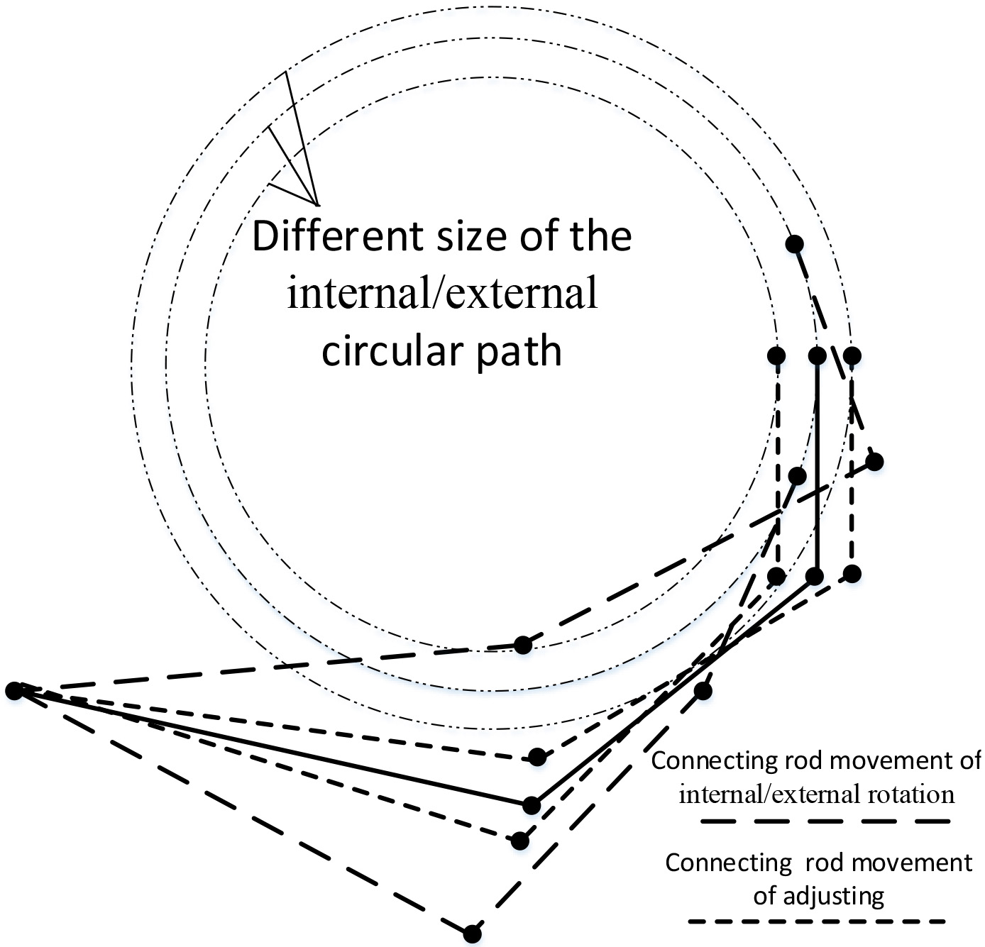
Figure 3 shows the structure of the hip. It was divided into three degrees of freedom in which the internal-external rotation and flexion-extension passed through the human movement axis, and the hip abduction/adduction was generated at the waist. The internal-external rotation of the design was composed of three hinge components. By positioning the three hinges, the end of the joint could have a rotational degree of freedom and move horizontally in a plane, as shown in Fig. 3. The plane freedom of movement could be adapted to the waist of different wearers within a certain range, and the structure automatically adapted to them when wearing it. The rotational degrees of freedom allowed the internal-external rotation to go through any axis.
Figure 2.
Hip structure.
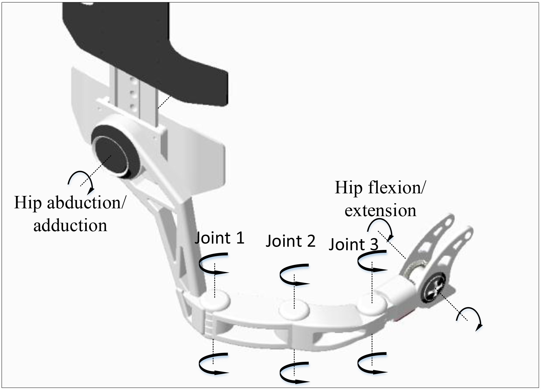
Figure 3.
Schematic diagram of hip.
2.4Knee joint
The knee is a single degree of freedom joint. It has an important supporting role for the whole body, and becomes the main torque output when the center of gravity in the body moves in the up and down directions.
Figure 4.
Knee structure.
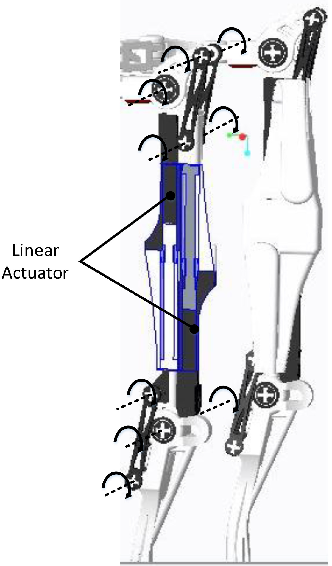
Figure 5.
Schematic diagram of knee.
Figure 5 shows the structure of the knee joint where the drivers of the knee and hip flexion/extension were both located in the thigh. By changing the driver position in the triangle rod, the linear driver could achieve output without moving with the controlled part, as shown in Fig. 5. This allowed the driver to have a more compact design compared with the conventional design. This approach made it easier to adjust the driver connection point, which made the adjustment range of change for speed and torque much larger, and the output capacity of the power source capable of being fully applied in practical applications.
2.5Ankle joint
As a connection of the leg to the foot, the ankle joint must have strong toughness. Except during level-walking and complex movement, its draw on the power source was small compared to the knee. From the body structure, its endurance capacity was stronger than the hip and knee. Considering overall quality and inertia problems, the design canceled the ankle drive and made it a passive joint.
The main movement of the ankle was flexion/extension, and internal/external rotation was approximated in the hips; therefore, it was provided only two degrees of freedom.
3.Kinematics modeling
In the movement of the human body, the torque output needed by a joint often requires promotion along with an increase of a joint angle [9]. Level-walking torque is far less than the torque needed when climbing a steep hill or complex terrain. However, the requirement of joint speed is not very important when the joint angle increases. Therefore, in the structure design, the maximum torque point needed to be moved as far as possible from the angle zero point. That way, when the wearer squatted or climbed complex terrain, there was a considerable amount of torque left; this was more consistent with human patterns of motion.
Figure 6.
Hip and knee simulation diagram based on the SAM software: a) Hip simulation diagram: Kinematics simulation performed in both hip and knee under the same conditions of the arrangement of space and the distribution of torque. The novel structure can improve the power efficiency in the large angle. b) Knee simulation diagram: In the condition of same force arm, the arrangement of the novel structure is more compact, and the torque can be considerable in the maximum angle.
Using SAM software, kinematics simulation was performed in both the hip and knee, and a comparison between the novel layout and conventional layout was made in the same space arrangement, as shown in Fig. 6. The curve in the figure references the torque needed for level-walking; although the novel link decreased the initial torque, it was still able to guarantee the level-walking torque requirement [10]. In addition, the peak of the torque moved backwards significantly; this solved the question of whether the torque demand increased along with the joint angle augment.
3.1Sensor information collection and feedback
The hydraulic cylinder was mainly controlled with force and position closed loop. Force sensors installed in the hydraulic cylinders of active joints measured the output force, and encoders were installed in the active joints by the gear drive. Considering the spatial arrangement of the joints, encoders were placed in the shank and the waist by utilizing a bevel gear drive, which is shown in Fig. 7. This kind of spatial arrangement made the space more compact, and also increased the accuracy of the encoder through the transmission ratio. According to the distribution of force, the force sensors set under the foot detected the human motion state [11].
Figure 7.
Arrangement of encoder.
During feedback processing, the device accurately calculated the immediate situation of the joint position and force by gathering information from the pressure sensors and encoders. Then, according to the encoders under the foot, it judged the body’s motion state. Through feedback, the difference between feedback value and expectancy value was calculated in order to adjust the output of the system; thus, the double closed loop of the force and the location was formed. This in turn controlled the position of the joints and the value of the speed and force [12].
4.Discussion and conclusion
The structure of the lower limb exoskeleton was designed using a differential mechanism of novel linkage joints. Different from the conventional design, the linear driver achieved power output without moving the controlled part. And benefitting from this idea, the hydraulic cylinder was placed inside the thigh, which made the structure more compact. Additionally, when in the maximum angle, there was a relatively large amount of torque remaining, which was more consistent with the human pattern of motion. There was a limitation in the initial angle, and although the peak torque moved backwards significantly, the novel link decreased the torque of the initial angle. As a result, when the weight was increased to a certain level, the human consumption increased in the initial angle. In follow-up work, in order to eliminate the limitations, the structure will be introduced in the initial angle to achieve a self-lock, and a reasonable control system will be designed.
Conflict of interest
None to report.
Acknowledgments
The work reported in this paper is funded by National Key Research and Development Program (Grant: 2016YFC0800607); National Nature Science Foundation of China (U1613219).
References
[1] | Chu A, Kazerooni H, Zoss A. On the biomimetic design of the berkeley lower extremity exoskeleton (BLEEX), Robotics and Automation, 2005. ICRA 2005.; Proceedings of the 2005 IEEE International Conference on. (2005) ; 4345-4352. |
[2] | Zoss A, Kazerooni H, Chu A. On the mechanical design of the Berkeley lower extremity exoskeleton (BLEEX), Intelligent Robots and Systems, 2005. (IROS 2005).; 2005 IEEE/RSJ International Conference on. (2005) ; 3465-3472. |
[3] | Amundson K, Raada J, Harding N, et al. Development of hybrid hydraulic – electric power units for field and service robots [J]. Advanced Robotics the International Journal of the Robotics Society of Japan. (2006) ; 20: (9): 1015-1034. |
[4] | Klaassen B, Linnemann R, Spenneberg D. Biologically Inspired Robot Design and Modeling. International Conference on Advanced Robotics, Coimbra, Portugal. (2003) ; 576-581. |
[5] | Zhang Q, Tian K, Guo H. Development of an Instrumented and Passive Exoskeleton for the Lower Limb Rehabilitation, Computer Science and Information Technology – Spring Conference, 2009. IACSITSC ’09; International Association of. (2009) ; 521-525. |
[6] | Kawamoto H, Hayashi T, Sakurai T, et al. Development of single leg version of HAL for hemiplegia, Engineering in Medicine and Biology Society, 2009. EMBC 2009; Annual International Conference of the IEEE. (2009) ; 5038-5043. |
[7] | Zoss AB, Kazerooni H, Chu A. Biomechanical design of the Berkeley lower extremity exoskeleton (BLEEX). Mechatronics, IEEE/ASME Transactions on. (2006) ; 11: (2): 128-138. |
[8] | El-Gohary M, Mcnames J. Human Joint Angle Estimation with Inertial Sensors and Validation with A Robot Arm[J].. IEEE Transactions on Bio-Medical Engineering. (2015) ; 621759-1767. |
[9] | Zoss A, Kazerooni H. Design of an electrically actuated lower extremity exoskeleton. Advanced Robotics. (2006) ; 20: (9): 967-988. |
[10] | Zhu Y, Zhang G, Zhang C, et al. Biomechanical modeling and load-carrying simulation of lower limb exoskeleton. [J]. Bio-Medical Materials and Engineering. (2015) ; 26: (s1): S729-S738. |
[11] | Bae J, Kong K, Byl N, et al. A mobile gait monitoring system for abnormal gait diagnosis and rehabilitation: a pilot study for Parkinson disease patients. [J]. Journal of Biomechanical Engineering. (2011) ; 133: (4): 269-279. |
[12] | Kazerooni H, Racine J-L, Huang L, et al. On the control of the berkeley lower extremity exoskeleton (BLEEX), Robotics and Automation, 2005. ICRA 2005; Proceedings of the 2005 IEEE International Conference on. (2005) ; 4353-4360. |


