
Effect of different expansion strategies on coronary stent deployment in a tapered artery
Abstract
BACKGROUND:
Vascular stenting has been widely used to treat vessel stenosis. However, long-term successes of the procedure are often compromised by late stent thrombosis (ST) and in-stent restenosis (ISR), especially in tapered arteries.
OBJECTIVE:
The aim of this study was to choose a reasonable expansion strategy for tapered arteries. METHODS: A balloon-expandable coronary stent deployment in a tapered vessel was numerically studied fol-lowing three strategies: (i) selecting the proximal diameter of the tapered vessel as the reference diameter to expand the stent, (ii) selecting the middle diameter of the tapered vessel as the reference diameter to expand the stent, and (iii) selecting the distal diameter of the tapered vessel as the reference diameter to expand the stent.
RESULTS:
Computational results showed that the first expansion strategy resulted in the maximum vessel stress and the best stent apposition, while the third strategy resulted in the minimal vessel stress and the worst stent appo-sition. Meanwhile, the second expansion strategy achieved a trade-off between the first and third strategies, leading to acceptable vessel stress and stent apposition.
CONCLUSIONS:
The second expansion strategy is the most reasonable choice for tapered vessels, and it should be considered when implanting a stent.
1.Introduction
A stent is a medical device, which is crimped and loaded on a balloon, and delivered to the stenotic region of an artery. After application, the stent can be plastically deformed through the inflation of the balloon. The stent remains in a deployed shape after the balloon is deflated. Although stenting has become a common procedure due to the minimally invasive nature and high initial success rate, long-term successes are usually compromised by late stent thrombosis (ST) and in-stent restenosis (ISR) [1, 2]. The situation becomes more complicated when the stent is implanted into a tapered vessel, since there is a diameter difference between the distal and proximal ends of tapered vessels, especially long ones. The surgeons must then decide on which diameter to base to choose a stent and then deploy the stent. On one hand, a larger diameter mismatch at the distal end of the tapered vessel could induce high arterial wall stresses, which have been associated with the formation of neointimal hyperplasia and ISR [3]. On the other hand, under-expansion or stent malapposition at the proximal end of the tapered vessel has been clinically associated with late ST [4]. Stent malapposition, also described as incomplete stent apposition (ISA), is a morphological characteristic defined by a lack of contact between the underlying vessel wall and at least one stent strut [5]. Several factors that contribute to ISA include the longer stents, reference diameter, and stent overlap [6]. The reference diameter is usually computed in accordance with the distal end of the tapered vessel when the stent needs to be deployed in the tapered vessels. This may result in ISA in the proximal end of the artery due to marked differences between the distal and proximal ends of the tapered artery. When ISA is detected, post-dilations with a non-compliant balloon in the ISA area are often used to deploy the stent and then obtain adequate apposition. However, aggressive post-dilations with balloons disproportionately larger than the nominal stent diameter may bring about further clinical complications, including stent fracture or artery wall dissection [7]. Accordingly, it is preferable to limit stent implantion to a single step approach that simultaneously considers stent apposition and vessel stress [8]. Since different expansion strategies lead to different results, it is critical to select an appropriate expansion strategy for tapered vessels.
Finite element method (FEM) has been widely applied to investigate the different mechanical properties of stents due to its low cost and high efficiency [9, 10, 11, 12, 13, 14]. Several studies have used FEM to investigate stent expansion modeling methods. Wang et al. [15] simulated the transient deployment process of the balloon and stent system with different balloon lengths and stent structures under internal pressures. Their research results showed that the dogboning phenomenon could be eliminated by varying the length of the balloon over the stent and/or by improving the geometry of the stent. Gervaso et al. [16] used three different methods to evaluate stent deployment in a vessel and the free-deployment of a stent. These stent deployment modeling techniques included: (1) modeling a deformable balloon, (2) loading a pressure on the internal surface of a stent, and (3) using a rigid surface deployed with displacement control. Beule et al. [17] studied the effects of the unfolding and expansion of balloons on the free-expansion of a stent. Up till now, most of computational studies have been limited to specific stent expansion modeling techniques for a single stent or for straight vessels; a detailed comparative study between different stent expansion strategies for tapered vessels is lacking, especially concerning the effects of expansion strategy choices on the biomechanical characteristics of stents.
This study numerically investigated a balloon-expandable coronary stent expansion in a tapered vessel. We followed three strategies in our investigation: (i) selecting the proximal diameter of the tapered vessel as the reference diameter to expand the stent, (ii) selecting the middle diameter of the tapered vessel as the reference diameter to expand the stent, and (iii) selecting the distal diameter of the tapered vessel as the reference diameter to expand the stent. Numerical results were compared to assess the extent of stent malapposition and vessel stress induced by stent expansion in each case.
2.Materials and methods
2.1Geometric models
The stent model generated via the Pro/Engineer was shown in Fig. 1. In order to save simulation time, only one-sixth of the stent model was used to determine the finite element model described below due to the circumferential symmetry of the stent. The stent had a length of 16.08 mm, an outer diameter of 1.36 mm, a strut thickness of 0.09 mm, a strut width of 0.09 mm, 6 units along the circumferential direction, and 5 units along the axial direction. The balloon model was generated as a cylindrical plane. The cylinder had a length of 16.28 mm, with the same diameter as the inner diameter of the stent.
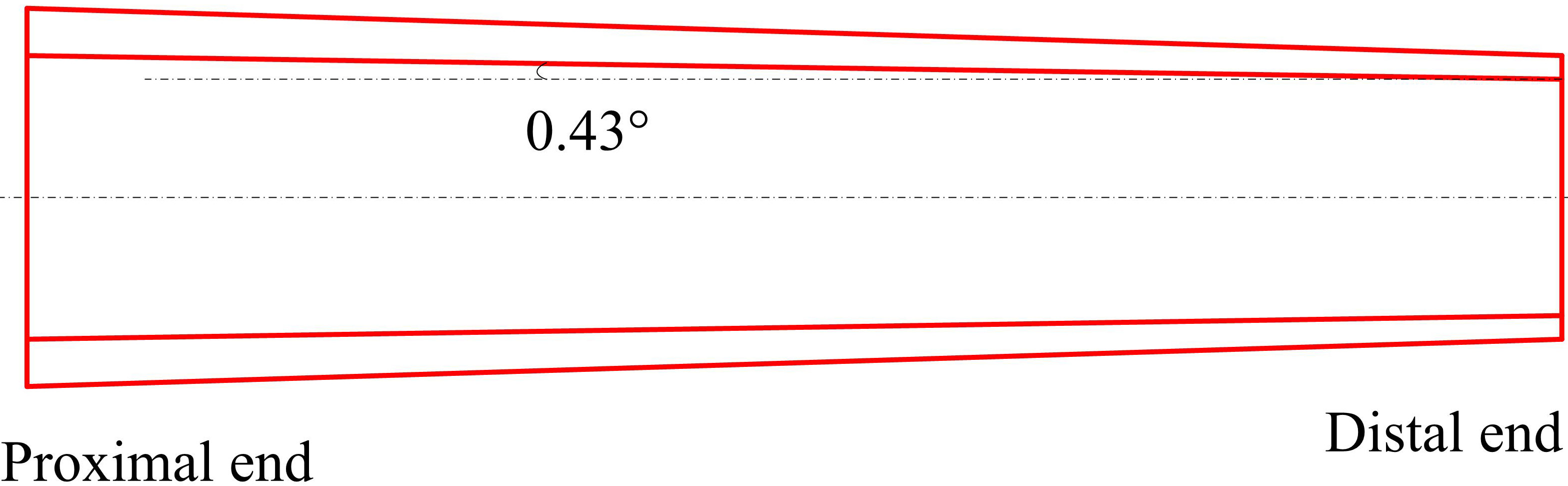
A tapered artery with an angle of 0.43
Table 1
Summary of dimensions for the tapered vessel models
| Tapering | Length (mm) | Proximal end | Distal end | ||
|---|---|---|---|---|---|
| Inner radius (mm) | Outer radius (mm) | Inner radius (mm) | Outer radius (mm) | ||
| 0.43 | 26 | 1.5 | 2.15 | 1.31 | 1.87 |
Figure 1.
Geometry of the stent.
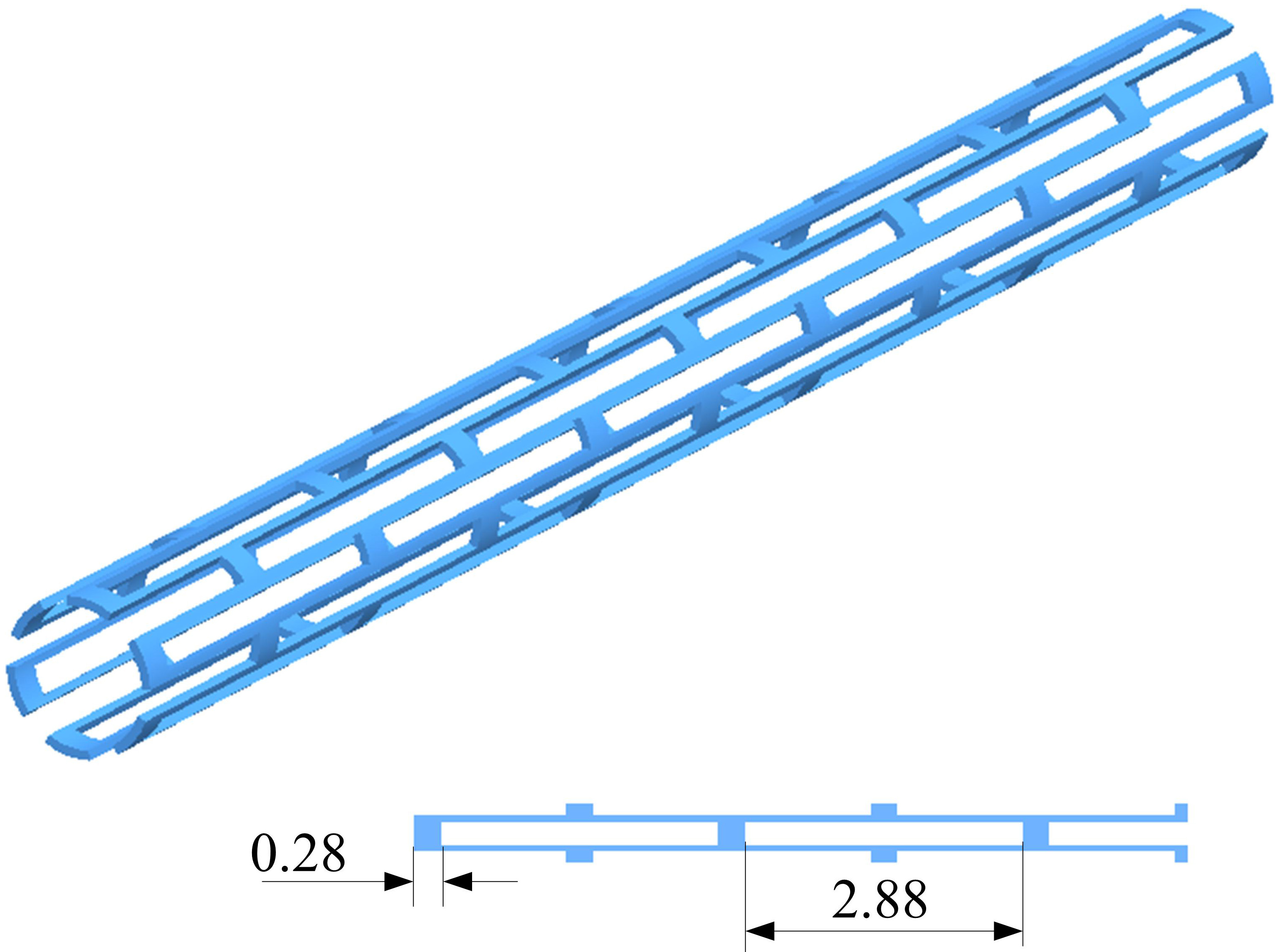
Figure 2.
Geometry of the tapered vessel.
2.2Meshing and material properties
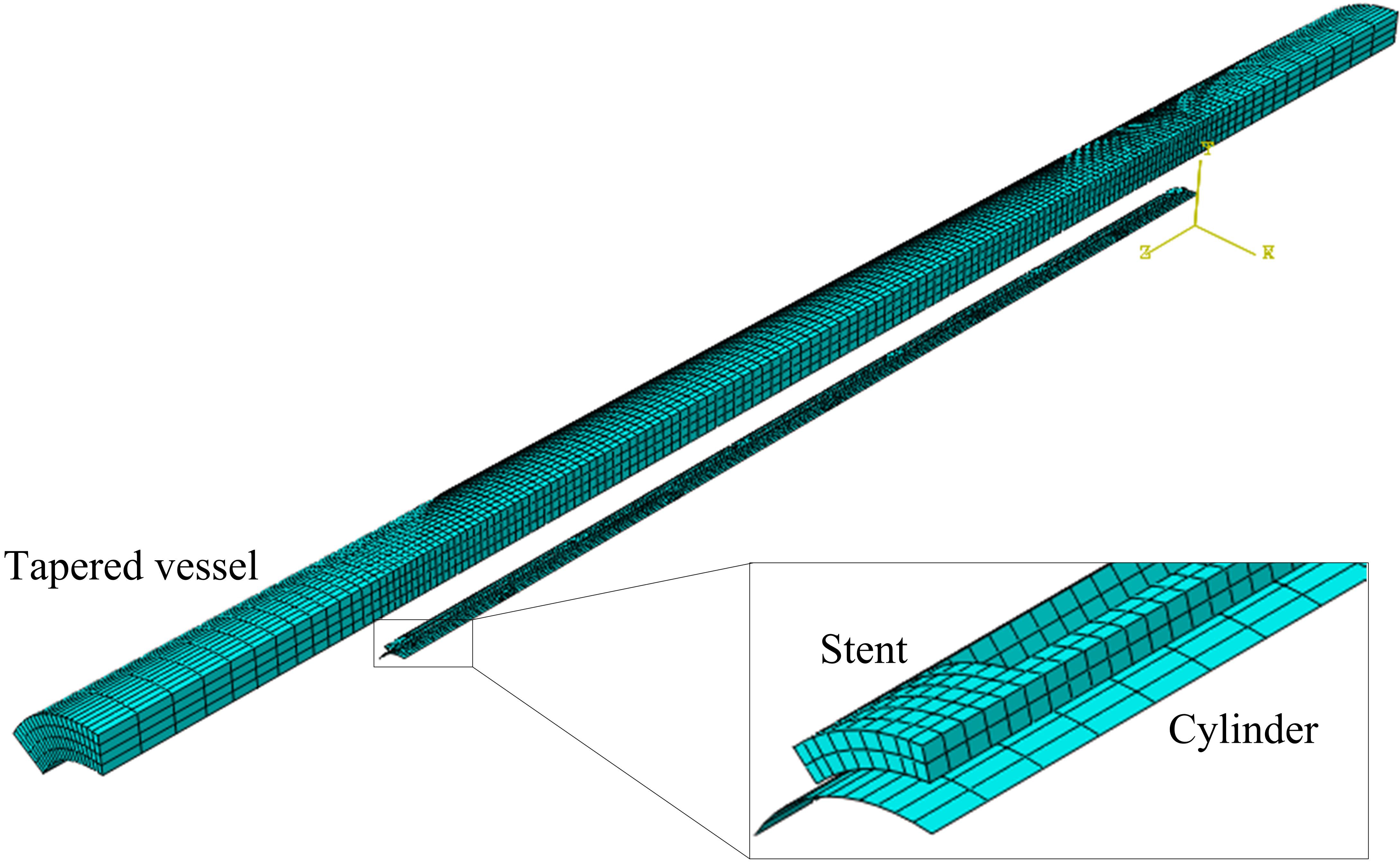
The finite element analysis (FEA) model of a stent deployment in a tapered vessel was shown in Fig. 3. The model was composed of a stent, a rigid cylinder, and a tapered artery vessel. The vessel, stent, and cylinder were coaxial, and the middle points of all axes were superimposed. The cylinder was meshed with quadrilateral elements, and consisted of 1440 elements. The stent was meshed with hexahedral elements and consisted of 3316 elements. The vessel was also meshed with hexahedral elements and consisted of 15360 elements. A sensitivity study was carried out to ensure enough meshing refinement.
The material property of the vessel was considered to have isotropic linear elasticity, with a Poisson’s ratio of 0.499 and a Young’s modulus of 1.75 MPa. The material of the stent was 316 L stainless steel, which was modeled with an elasto-plastic stress-strain relationship with nonlinear hardening behavior. The material had a Young’s modulus of 201 GPa, a yield stress of 330 MPa, a Poisson’s ratio of 0.3, and a limit stress of 750 MPa.
2.3Conditions and loading
The stent was fixed in the axial direction at nodes on its central symmetric plane. Both ends of the artery were fixed. The symmetry planes of the vessel were constrained in the circumferential direction, while the balloon was constrained in both circumferential and axial directions. Rotation of all components was inhibited. The cylinder expanded the stent with a controlled predefined displacement. This method has been proven as an optimal choice when simulating stent expansion [9], since it was less computationally expensive. A radial displacement was imposed on the nodes of the cylinder to simulate balloon inflation. Both inflation time and deflation time were chosen to be 10 ms. A quasi-static procedure of Abaqus/Explicit solver was adopted for the large deformation analyses. Surface-to-surface contacts were created between the outer cylinder and the inner surface of the stent, as well as between the inner surface of the vessel and the outer surface of the stent. All contacts had a frictional coefficient of 0.2 [14].
Table 2
Summary of different expansion strategies for the stent sizing decision
| Expansion | Reference | Original inner diameter | Nominal diameter of stent (mm) | Radial displacement load |
|---|---|---|---|---|
| strategies | diameter | of vessel (mm) | ||
| S1 | Proximal | 3.00 | 3.30 | 0.97 |
| S2 | Middle | 2.81 | 3.09 | 0.87 |
| S3 | Distal | 2.62 | 2.88 | 0.76 |
Note: The nominal diameter (i.e. expansion target diameter) of the stent is 10% larger than the reference diameter.
Figure 3.
Finite element models of a stent deployment in a tapered vessel.
3.Results
3.1Effect of expansion strategies on arterial mechanics
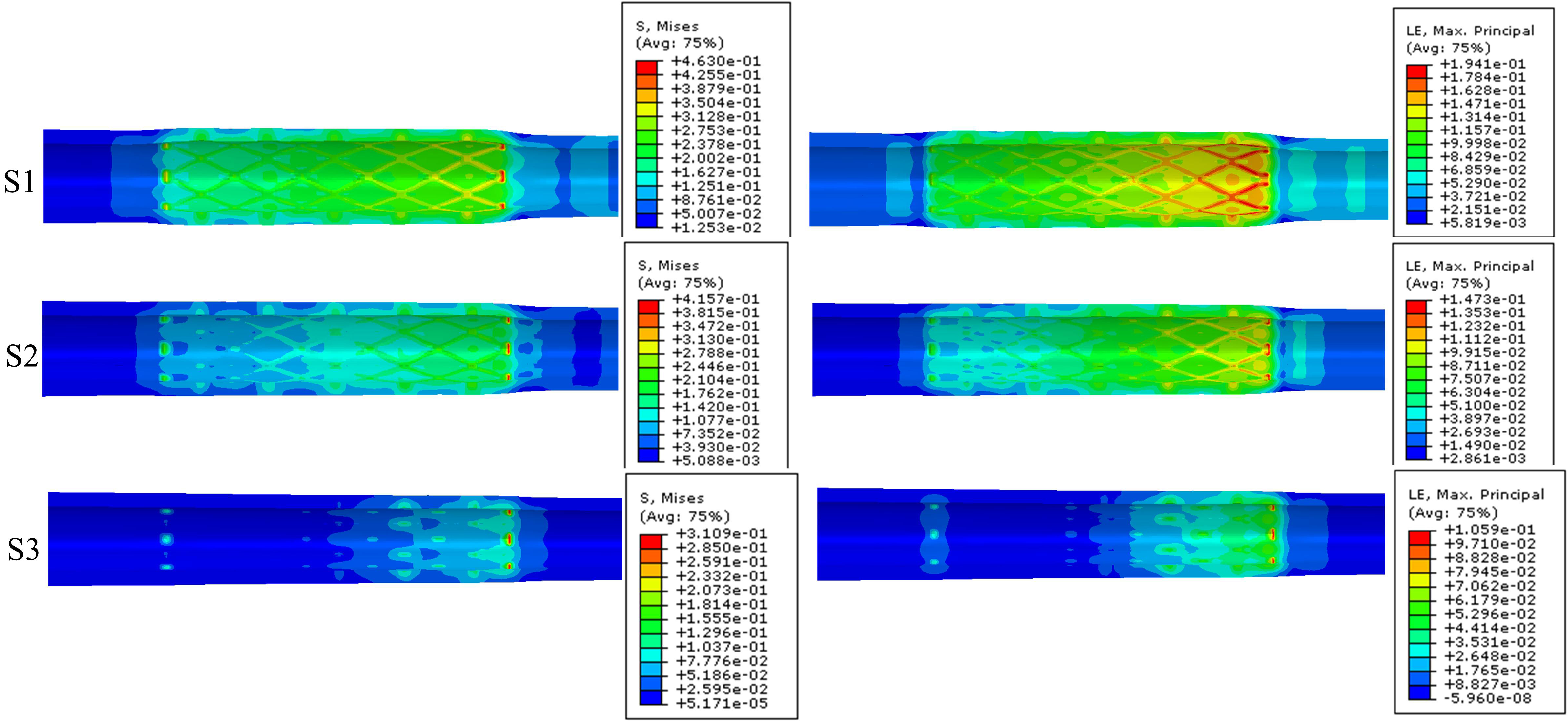
Figure 4 shows the stent-induced stress and strain distribution on the artery wall when the stent was deployed to the nominal diameter. The Von Mises (VM) stresses on the arterial wall were higher at the distal region of the tapered artery than that at the proximal region of the artery. Moreover, the different stent expansion strategies caused deviations in arterial stress and strain. The maximum VM stress on the arterial wall was 0.4630 MPa for the expansion strategy S1; 0.4157 MPa for the expansion strategy S2; and 0.3109 MPa for the expansion strategy S3. The maximum principal logarithm strains induced by the stent in the expansion strategies S1, S2, and S3 were 0.1941, 0.1473, and 0.1059, respectively. This illustrates that the mechanical environment of the vessel underwent the most alterations with the first expansion strategy (S1). Among the three expansion strategies, the first expansion strategy (S1) resulted in the maximum vessel stress, while the third strategy (S3) resulted in the minimum vessel stress.
Figure 4.
Stent-induced stress (left) and strain (right) distribution on artery wall when stent was expanded to nominal diameter.
3.2Effect of expansion strategies on stent apposition
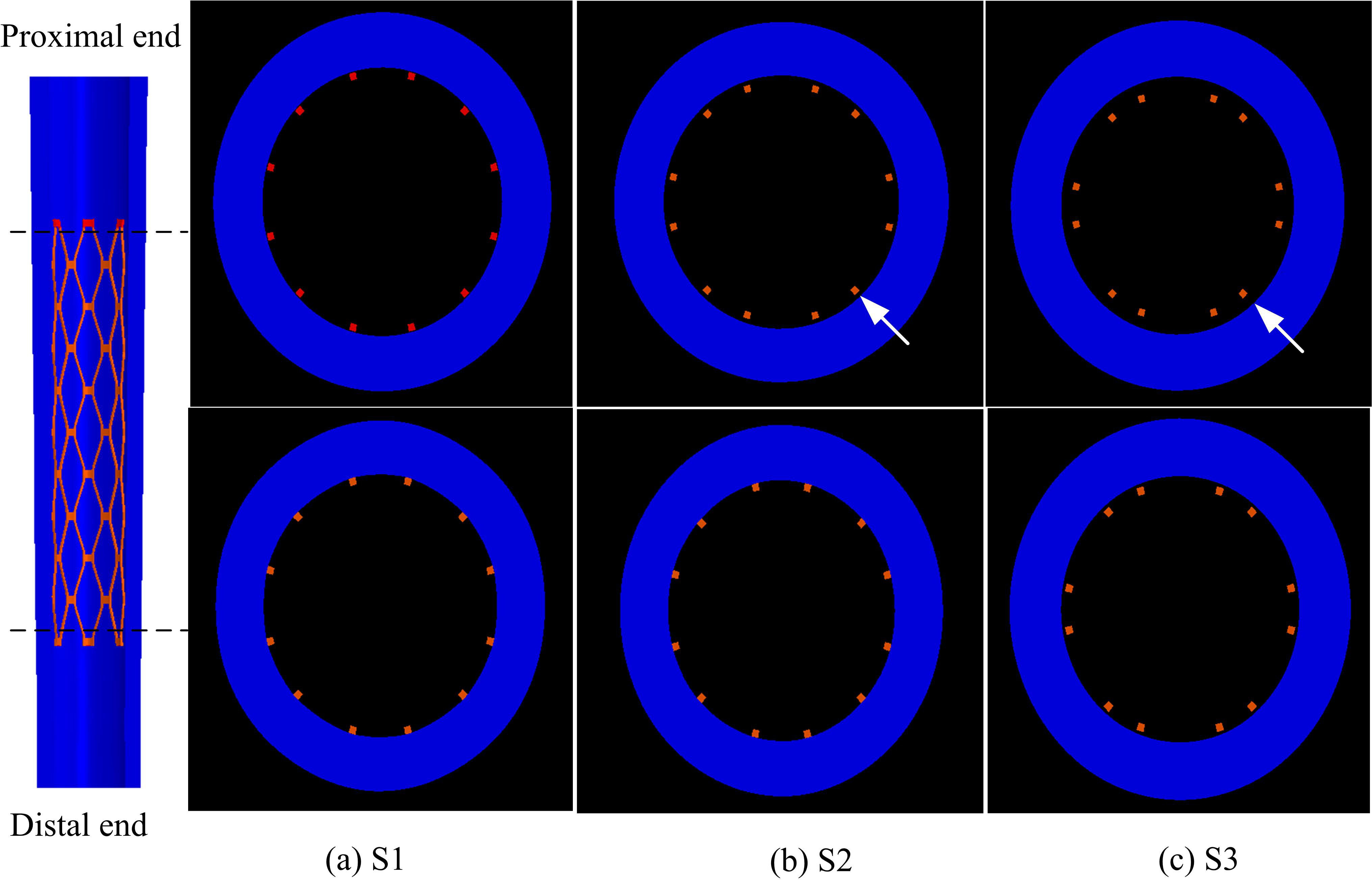
Figure 5 shows stent malapposition in the distal and proximal ends after the stent deployment. Based on these deformed configurations, the distance between the struts and the inner arterial wall was calculated in order to quantify the stent strut apposition. The expansion strategy S1 resulted in the best stent apposition (Fig. 5(a)) both at its proximal and distal ends. However, the expansion strategy S2 and S3 showed similar results that the stent malapposition occurred predominantly at the proximal end of vessel (Figs 5(b) and (c) arrows). The maximum distance between a stent node and a vessel wall node was 0 mm, 0.0657 mm, and 0.1507 mm for the expansion strategy S1, S2 and S3, respectively. Therefore, the expansion strategy S1 resulted in the best stent apposition, followed by the expansion strategy S2. However, the expansion strategy S3 resulted in the worst stent apposition, especially at the proximal end (Fig. 5(c) arrow). It should be noted that incomplete stent apposition is strongly associated with ISR and stent thrombosis.
Figure 5.
Stent malapposition after the stent deployment. Cross section images were taken at the proximal (top) and distal (bottom) area (broken lines) of the model.
4.Discussion
This study investigated the effects of various stent expansion strategies through the finite element method. A model of stent deployment in tapered vessels was herein developed to evaluate the importance of reference diameter selection where vessel wall stresses and stent apposition are concerned. Investigating the results on the arterial wall and stent apposition verified the differences caused by the three expansion strategies used. The study shows that the larger the reference diameter, the better the stent apposition. However, it also shows that the larger the reference diameter, the greater the vessel stress induced by stent expansion. More specifically, where arterial wall stress is concerned, the distal diameter-referenced expansion strategy is potentially the best choice for tapered vessels among the three expansion strategies, since it resulted in the lowest vessel stress during stent expansion. Therefore, this strategy offers the lowest possibility of injury to the vessel wall. The proximal diameter-referenced expansion strategy led to the highest vessel stress. High arterial stress induced by stent expansion has been predicted by previous studies [11, 12, 13, 14], and arterial wall stress has been associated with the formation of neointimal hyperplasia and in-stent restenosis [3]. On the other hand, the proximal diameter-referenced expansion strategy may be the best choice for tapered vessels where stent apposition is concerned. This is because the above strategy led to the best stent apposition both at the proximal and distal ends of the stent. Contrastingly, the distal diameter-referenced expansion strategy resulted in the worst stent apposition, especially at the proximal end. It should be noted that incomplete stent apposition of bare metal stents and/or drug-eluting stents is strongly associated with ISR and stent thrombosis [4]. Therefore, in order to reduce or even avoid the occurrence of ISR and stent thrombosis, the vessel stress caused by stent expansion and stent apposition should be considered. Fortunately, the middle diameter-referenced expansion strategy can achieve a trade-off between the proximal diameter-referenced expansion strategy and the distal diameter-referenced expansion strategy, resulting in adequate stent apposition and vessel stress. Therefore, the middle diameter-referenced expansion strategy may be an appropriate choice for tapered vessels.
5.Conclusions
The approach proposed in this paper evaluated and compared different expansion strategies used with balloon-expandable stents in tapered arteries. We found that the biomechanical behavior of a stent was affected by the stent expansion strategy, though its performance was more strongly influenced by the structural design of the stent itself. Moreover, the stent expansion strategy that was selected significantly affected the stress induced in the underlying tissue and the stent apposition properties. The proximal diameter-referenced expansion strategy provided the best apposition, but it resulted in the highest vessel stress during stent expansion, which has been associated with serious injury to the vessel wall. The distal diameter-referenced expansion strategy induced the lowest vessel stress during stent expansion, but resulted in the most pronounced ISA. Compared to the above strategies, the middle diameter-referenced expansion strategy achieved a trade-off between the proximal diameter-referenced and the distal diameter-referenced expansion strategies, resulting in adequate stent apposition and vessel stress. Therefore, the middle diameter-referenced expansion strategy is recommended for tapered vessels. Prior to a stent procedure, this method can be adopted to predict stent apposition and vessel wall stress, and thereby select the superior stent to be implanted in tapered vessels.
Conflict of interest
None to report.
Acknowledgments
This project is supported by National Natural Science Foundation of China (51305171), Natural Science Foundation of Jiangsu Province (BK20130525), Natural Science Foundation of the Higher Education Institutions of Jiangsu Province (13KJB460006), China Postdoctoral Science Foundation (2011M500858), Foundation of Jiangsu University (10JDG123) and Project of Jiangsu University for training young backbone teachers.
References
[1] | Kim MS, Dean LS. In-stent restenosis. Cardiovasc Ther. (2011) ; 29: (3): 190-198. |
[2] | Cook S, Ladich E, Nakazawa G, Eshtehardi P, Neidhart M, Vogel R. Correlation of intravascular ultrasound findings with histopathological analysis of thrombus aspirates in patients with very late drug-eluting stent thrombosis. Circulation. (2009) ; 120: (5): 391-399. |
[3] | Timmins LH, Miller MW, Clubb FJ, Moore JE. Increased artery wall stress post-stenting leads to greater intimal thickening. Lab Invest. (2011) ; 91: (6): 955-967. |
[4] | Ozaki Y, Okumura M, Ismail TF, Naruse H, Hattori K, Kan S. The fate of incomplete stent apposition with drug-eluting stents: an optical coherence tomography-based natural history study. Eur Heart J. (2010) ; 31: (12): 1470-1476. |
[5] | Attizzani GF, Capodanno D, Ohno Y, Tamburino C. Mechanisms, pathophysiology, and clinical aspects of incomplete stent apposition. J Am Coll Cardiol. (2014) ; 63: (14): 1355-1367. |
[6] | Ragkousis GE, Curzen N, Bressloff NW. Simulation of longitudinal stent deformation in a patient-specific coronary artery. Med Eng Phys. (2014) ; 36: (4): 467-476. |
[7] | Hanratty C, Walsh S. Longitudinal compression: a “new” complication with modern coronary stent platforms – time to think beyond deliverability? Eurointervention. (2011) ; 7: (7): 872-877. |
[8] | Ragkousis GE, Curzen N, Bressloff NW. Multi-objective optimisation of stent dilation strategy in a patient-specific coronary artery via computational and surrogate modeling. J Biomech. (2016) ; 49: (2): 205-215. |
[9] | Beule MD, Mortier P, Carlier SG, Verhegghe B, Impe RV, Verdonck P. Realistic finite element-based stent design: The impact of balloon folding. J Biomech. (2008) ; 41: (2): 383-389. |
[10] | Hsiao HM, Yeh CT, Chiu YH, Wang C, Chen CP. New clinical failure mode triggered by a new coronary stent design. Bio-Med Mater Eng. (2014) ; 24: (1): 37-43. |
[11] | Imani SM, Goudarzi AM, Valipour P, Barzegar M, Mahdinejad J, Ghasemi SE. Application of finite element method to comparing the NIR stent with the multi-link stent for narrowings in coronary arteries. Acta Mech Solida Sin. (2015) ; 28: (5): 605-612. |
[12] | Schiavone A, Zhao LG, Abdel-Wahab AA. Effects of material, coating, design and plaque composition on stent deployment inside a stenotic artery-Finite element simulation. Mater Sci Eng C. (2014) ; 42: : 479-488. |
[13] | Ragkousis GE, Curzen N, Bressloff NW. Computational modelling of multi-folded balloon delivery systems for coronary artery stenting: insights into patient-specific stent malapposition. Ann Biomed Eng. (2015) ; 43: (8): 1786-1802. |
[14] | Wu W, Gastaldi D, Yang K, Tan L, Petrini L, Migliavacca F. Finite element analyses for design evaluation of biodegradable magnesium alloy stents in arterial vessels. Mater Sci Eng B. (2011) ; 176: (20): 1733-1740. |
[15] | Wang WQ, Liang DK, Yang DZ, Qi M. Analysis of the transient expansion behavior and design optimization of coronary stents by finite element method. J Biomech. (2006) ; 39: (1): 21-32. |
[16] | Gervaso F, Capelli C, Petrini L, Lattanzio S, Virgilio LD, Migliavacca F. On the effects of different strategies in modelling balloon-expandable stenting by means of finite element method. J Biomech. (2008) ; 41: (6): 1206-1212. |
[17] | Beule MD, Mortier P, Carlier SG, Verhegghe B, Impe RV, Verdonck P. Realistic finite element-based stent design: The impact of balloon folding. J Biomech. (2008) ; 41: (2): 383-389. |
[18] | Datir P, Lee AY, Lamm SD, Han HC. Effects of geometric variations on the buckling of arteries. Int J Appl Mech. (2011) ; 3: (2): 385-406. |


