
An ontology of 3D environment where a simulated manipulation task takes place (ENVON)
Abstract
Thanks to the advent of robotics in shopfloor and warehouse environments, control rooms need to seamlessly exchange information regarding the dynamically changing 3D environment to facilitate tasks and path planning for the robots. Adding to the complexity, this type of environment is heterogeneous as it includes both free space and various types of rigid bodies (equipment, materials, humans etc.). At the same time, 3D environment-related information is also required by the virtual applications (e.g., VR techniques) for the behavioral study of CAD-based product models or simulation of CNC operations. In past research, information models for such heterogeneous 3D environments are often built without ensuring connection among different levels of abstractions required for different applications. For addressing such multiple points of view and modelling requirements for 3D objects and environments, this paper proposes an ontology model that integrates the contextual, topologic, and geometric information of both the rigid bodies and the free space. The ontology provides an evolvable knowledge model that can support simulated task-related information in general. This ontology aims to greatly improve interoperability as a path planning system (e.g., robot) and will be able to deal with different applications by simply updating the contextual semantics related to some targeted application while keeping the geometric and topological models intact by leveraging the semantic link among the models.
1.Introduction
Modern manufacturing and supply-chain industries are increasingly using robots to automate material handling and machining in the shopfloor and warehouse environment. The key part of the information related to any 3D environment, where a simulated manipulation task is carried out by CNC machines, robots and automated vehicles [64], may include different levels of abstractions, such as context, topology, and geometry. Distributed manufacturing and supply-chain operations require a common set of vocabulary for such a 3D environment to exchange information between control rooms, responsible for planning, and control at the shopfloor or the warehouse regarding tasks and path planning for the robots and equipment in this heterogeneous environment. Ameri et al. discussed why the interoperability of the exchanged information is the key to the digital transformation of modern manufacturing and supply chain, additionally showing why ontology fares better than traditional manufacturing data standards, and finally suggesting pervasive adoption of integrated ontologies based on a common foundation [2].
Furthermore, the traditional product development process in PLM (Product lifecycle management), which heavily rely on 3D modelling for designing products, is not only about the structural information of the physical product and its components but also their kinematic and static behaviors in relation to the environment, other objects that the product will interact with, and the functional requirements that the product aims to satisfy. 3D Computer-Aided Design (CAD) modelling, starting from the mid of the 1960s, uses the power of computers to support the creation, modification, analysis, and optimization of a product using virtual prototypes [54]. This area also requires both accurate geometrical information and a higher-level functional description of the product and its parts to perform functional and integration tests on virtual prototypes. Lacking this level of completeness in the product model, the physical prototypes are often interleaved with the virtual prototypes in the V-cycle product development process [11], with the latter being used only at the conceptualization phase and the former for rigorous quality assurance. Virtual prototypes are also widely used for simulation purposes. Different simulation software (e.g., DMU kinematics for CATIA®,11 Motion modules for Solidworks®,22) carry out the kinematic analysis of a system and verify whether the system can function correctly. Lack of connection among different levels of abstractions of the 3D environment results in information loss and ambiguous identification of virtual entities in the simulated environment. For example, geometrical models are not linked to spatial and topological information, and geometrical objects do not express how these objects are viewed in different contexts. This type of disconnected modelling approach does not allow for fast queries, such as “what is the central axis of Object A or Hole B?”, which mixes both a geometrical entity (e.g., central axis) and a context-dependent entity (hole). Moreover, without adhering to formal logic, these models do not provide inference support to determine queries like “whether Object A fits Hole B?”, as such a query needs a model of “fitness” to be successful.
Along with the emergence of digital simulation techniques and more recently Virtual Reality, industrial and institutional stakeholders have expressed the need to validate complex scenarios through simulation. In industry, as the economic context becomes more and more competitive, products are more and more integrated, and the tasks are associated with their lifecycle. Whether performed by human operators or robots, the operations must be carried out under potentially very strong geometric constraints. When validating such complex scenarios, showing the feasibility of motion is key. Automatic motion planning techniques have been developed by the robotics community since the 1980s on to tackle this issue [40].
In [13], we classified the motion planning techniques:
- according to the environment models used (we distinguish global approaches where a map of the whole environment is used, and local approaches when local models of the neighborhood of the objects displaced are used)
- according to the way these models are explored (using deterministic or probabilistic exploration techniques).
The techniques based on a global approach and a deterministic exploration of the environment model use a full or exact (up to the resolution of the model) geometric model of the free space are complete in resolution, but the time needed to complete the models becomes prohibitive for complex and high dimensional environments, whereas techniques involving local approaches and deterministic exploration (typically using potential fields) are not complete and may fail (dead end case). The techniques involving a global approach and a probabilistic exploration of the global model also face the complexity of the model. The techniques involving a local approach and a probabilistic exploration method (typically involving the local development of a growing roadmap made of random configurations) integrate iteratively new randomly drawn configurations to the tree under construction until the start and goal configuration are connected. Probabilistic methods are probabilistically complete; however, these methods employ blind search, that they search in a large solution space and do not guarantee finite-time solutions.
The limitations of these (deterministic or probabilistic) techniques are mainly linked to the complexity of the traditionally pure geometric environment models involved; neither the environment models nor the strategies to explore these models are based on information related to the task to be performed. In a complex environment, automatic path planning algorithms may lead to high processing times, either fail, or provide solutions of little relevance for the task to be performed. Even a comparatively simple task like the insertion of a pen into a pen box is very challenging for motion planning if to be performed under strong geometric constraints (also guided the designs of scenarios used in Section 5.1 for evaluation). Motion planners, even in the case of an existing solution, may lead to very high processing times, and propose paths of little relevance to the task to be performed [39,70].
Different solutions, that are currently explored by the robotics community to tackle these limitations, are:
- collaborative approaches between a human operator and path planning algorithms [24,38], taking advantage of both the computational capacities of the motion planning algorithms and the cognitive capacities of the human operator in interaction or immersion. Unfortunately, they rarely allow continuous interaction.
- approaches jointly considering task and motion planning (TAMP) to bridge the gap between the low-level (motion planning techniques, developed by the robotics community) and the high-level (task planning techniques, developed by the AI community). In the robotics field [14,34,56], works found in the literature usually perform classical task planning first and then associate the resulting elementary tasks (constituting the task plan) to path planning requests for checking feasibility. However, the interoperability between task and path planning needs to be improved, notably, from the point of view of insufficient feedback between the low-level (feasibility of motion) and the high-level (need for improvement of the use of this information for task planning). The integration of task and motion planning is only emerging and is a strong challenge. Here, ontology is a promising tool.
The robotics scientific community has widely shown interest in using higher abstraction level information (namely topology and semantics) when modelling the environment than the purely geometric traditionally used, see e.g. for environment modelling [26,43,49,65,66], robot localization [61,62], navigation [20], motion planning [11], task planning [25,32,33], task and motion planning [1,21], etc.
Thus, a transverse need appears to consider in many robotics scientific fields to use a higher abstraction level when modelling the environment than the purely geometric data, which is still used most of the time, this need is expressed virtually for any kind of task to be performed by a robot or set of robots.
To address this issue, we propose an ontology for environment modelling applicable to any robotic manipulation task. This ontology is inspired by the multi-level environment model, which captures information about both rigid body and free space from geometrical, topological, and contextual perspectives. Such a multi-level environment model was first proposed by Cailhol et al., who showed that by including both the free space and the obstacles (considered as rigid bodies in this paper) in the environment; the model has proven to be very efficient for the semantic control of motion planning for robotics [12] and offers strong potential for the assistance to the validation of complex manipulation tasks in Virtual Reality [11]. Below, we provide a list of unique contributions of our work presented in this paper.
1. Development of an ontology capturing rich semantic models for the 3D environment.
2. Inclusion of the representations of both rigid body and free space.
3. Integration of different levels of abstraction (geometrical, topological, and contextual).
4. Fulfilment of the information exchange and reasoning requirements for robotic tasks (manipulation, navigation, localization).
5. Bridging the gap between task and motion planning as an environment model usable by both levels (low level – motion planning and high level – task planning)
6. Evaluation based on test scenarios from object manipulation under strong geometric constraints.
To evaluate the proposed ontology model, we focused on validating our approach using simulations of manipulation tasks, performed under strong geometric constraints. In both scenarios, a particular object has to be moved from the initial configuration to a finthel one. A configuration is defined by the 3D position, orientation, and shape of the manipulated object. Validating these scenarios consists of testing the feasibility of the corresponding motion planning queries.
As discussed in Section 5.1, the two scenarios chosen (insertion of a pen into a penbox, and shapes games for babies) are: a) extremely challenging for motion planning as the tasks are to be performed under very strong geometric constraints, b) representative of generic tasks to be performed when assembling, disassembling or maintaining real industrial systems and c) generic enough to ensure the objectivity of our validation.
The rest of the paper is organized as follows. Section 2 overview of the existing research on the related topics. Section 3 presents the objective, requirements analysis and competency questions of our proposed ontology for environment modelling (ENVOn). Section 4 gives a detailed description of ENVOn. We discussed why different abstraction levels of environment information should be considered (i.e., context, topology, and geometry) in an integrated framework. We have applied a modular architecture to the proposed ontology. We will describe how a concept might have different meanings at different abstraction levels. Section 4 presents the ontology validation results. Section 5 presents the validation of ENVOn through two simulation scenarios. The evaluation of each of the two scenarios is presented and discussed. Section 6 presents the conclusion and future works.
2.State of the art
In the following, we explore past studies in data models that were developed for both robotic applications focusing on an environment composed of both free space and rigid bodies, and CAD applications focusing on geometric information of 3D design of solid bodies.
The semantic information of an environment is made of the types of objects, their locations in the space, and their semantic identity. This kind of information model, which is formally called a ‘semantic environment map’ [45], has already been discussed in knowledge representations for path planning in robotics, such as navigation maps and collision maps, especially for the manufacturing environment [8]. Rusu presented a semantic 3D object map to annotate environment objects and their surfaces with semantic labels [51]. It consists of a 3D point cloud perceived from robot perception (e.g. vision [17], touch [63]), polygonal models of objects constructed from clustering and segmentation of the point cloud, and a semantic interpretation of objects and their surfaces. It serves as a semantic resource to determine the final grasp or placement position for manipulation. For example, in an indoor kitchen environment, a robot may need to locate the hinge of a drawer when the robot is given a high-level command to open the drawer. Certain works of Marton [41] and Blodow [7] only concern modelling environments from a specific context, e.g., a kitchen.
Among the models that use richer semantics, KnowRob [59], a Prolog-based knowledge processing system capable of accessing OWL ontologies, captures the encyclopedic knowledge to describe the types and the properties of objects (e.g. refrigerator, drawer, micro-oven in a kitchen) as well as the commonsense knowledge to describe the everyday usages for these objects.
In an ontology-based multi-layered robot-knowledge framework, called OMRKF [31], the environment knowledge model for the robot has three levels: 1) object features level describes the visual attributes, e.g., colours, textures, and features, that are used to recognize an object, 2) object identity level that forms the taxonomy of these objects, and 3) space level that describes the taxonomy of locations, e.g. living room and bedroom. In both KnowRob and OMKRF, the environmental model is application-specific and only concerns information related to the operations of the robot. However, they do propose basic connectivity among the locations of free space models. For example, KnowRob model defines the concept ‘Place’ to designate relevant locations in an environment and the concept ‘Map’ as an abstract symbol for topologically mapping those places in an environment. OMKRF model describes the taxonomy of different locations of an environment. A topological map is used to describe the connectivity among the locations. However, in both cases, the structure of the topological map is not defined. They are also incomplete as only relevant locations are identified as places.
The most important facet of knowledge modelling for the robotic environment is to utilize geometric constraints to determine accessibility and localization with fast queries. For example, to localize the top face of a table so that a robot can put down a bottle on it or understand the constraints of holding a cup upwards. The environment where a simulated manipulation task takes place is mostly considered a closed part of the 3D Cartesian space cluttered with mobile/fixed obstacles (regarded as a rigid body). These rigid bodies are built on CAD models. Recently, the environment model proposed by Cailhol et al. [12] consists of a rigid bodies model and a free-space model. Both of them involve different levels based on semantic, topologic, and geometric information. Regarding formal schema for capturing the geometry of rigid bodies, STEP (STandard for Exchange of Product model data) [48] is developed by the ISO organization (referenced as ISO 10303) to meet the needs of modern industry to facilitate the exchange of product data (including the CAD models) among different phases of product’s development or different organizations. Among various schema developed under the aegis of STEP, AP203 (Configuration-controlled 3D design of mechanical parts and assemblies) is the most widely used application protocol [16] that closely follows Boundary Representation (BREP) for 3D models. OntoSTEP is an effort by Barbau et al. to translate the STEP schema directly into an ontology model formalized in OWL [4]. An implementation of a particular product thus can be instantiated in the defined ontology model. However, the automated extracted taxonomy of AP203 and AP214 does not contain semantics for real entities as STEP standards often employ concepts that do not have any semantic relevance but are only used to better organize the geometrical and topological data. However, AP24233 has addressed some of these shortcomings by introducing a feature library following the model-based design principle. Still, a further update on OntoSTEP for AP242 is yet to be published.
Perzylo et al. construct an ontology model defining boundary representations (BREP) of objects from scratch without referring to STEP [46]. This ontology consists of a topological part, illustrating the topological connectivity and orientations of vertices, edges, and faces of a geometric part, describing the geometric primitives relating to the topological part (i.e., points, curves, surfaces). Yet, it is still limited to the boundary representation of CAD objects, whereas other models (such as Constructive Solid Geometry, abbreviated as CSG) are also possible to illustrate the geometries of CAD objects. Ontology for 3D shapes can also be found in the work of Sarkar and Sormaz [55] who used foundational concepts and relationships described by the top-level ontology BFO (Basic Formal Ontology) in their model to ensure the interoperability of the 3D design information. This ontology also makes a distinction among the geometric entities and various representational schemes by which they are encoded, e.g., various types of polynomial equations for representing a curve in space, and BREP or CSG techniques for representing complex solids.
The difference in the viewpoints in modelling the 3D objects is also apparent in the models of free space. Two main techniques have been used to synthesize the geometries of a free space model: cell decomposition and roadmap model. According to how the cells are formed, the related works can be classified in mainly four categories: Exact cells [19], Rectangular Cells [10], Regular Cells [52], Unbalanced Trees [52] (quadtree in 2D space and octree in 3D space). Roadmap models the points of interest and interconnects them as a graph to describe the connectivity of the free space. This technique reduces the amount of information required by cell decomposition of the entire space as only relevant portions of space are included.
From the topological viewpoint, free space needs to be synthesized to represent connectivity, such as the reachability between different locations. In the studies on robotic applications, the arc connecting two views is represented as the state transition of the environment as the robot’s sensory perception changes. Kortenkamp et al., Dedeoglu et al., and Kuipers et al. [18,36,37] propose the construction of a topological map using distinct views as nodes and their transitions as arcs. Similar to the efforts of focusing only on the interesting part of the views, Hirtle et al. and McNamara [29,42] define ‘region’ as a unique location in space. Mozos et al. [43] propose to construct spatial regions by detecting doorways. Cailhol et al. [12] define a topological graph to seize the connectivity of the free space in the environment. The graph connects places to cross and borders to reach; the places and borders are automatically extracted from a geometric model of the free space using an octree, by using a process inspired by region-growing algorithms used in computer vision [23].
Similar to rigid bodies, the semantic information of the free space model varies among applications, and it must be adapted to the tasks proceeded by applications. For example, for indoor robotic applications, both common-sense and encyclopedic knowledge [59] can be used to annotate different household locations, such as the kitchen, corridor, and bedroom. ‘Semantic map’ in the literature [25,44,69] captures the human’s point-of-view of the environment where tasks are performed. It associates the semantic information (the taxonomy of locations, like room, corridor, and their properties) with the places constructed at the topologic level and also their geometric description at the geometric level. Regarding information about geographical location, GeoSPARQL [5] is a standard model for expressing geospatial locations. Some efforts were also spent by researchers to convert IFC standard for BIM (Building Information Modeling) in OWL ontology [60]. Although these works substantiate the efficacy of admitting multiple viewpoints in the model, they do not adopt a rigorous knowledge modelling framework to link these viewpoints.
Finally, despite their acknowledgement of the need of taking different aspects of the environment into account, none of these ontologies has considered modelling the environment information from different viewpoints (i.e., context, topology, geometry) for both the rigid bodies and the free space models together in an evolvable ontology. Such an integrated semantic model will also allow fast queries to be executed in any environment information and possibly infer new knowledge. More importantly, rather than manually assigning the tedious geometric constraints to a primitive action, they can be automatically inferred based on the information related to a primitive action to be performed (e.g., the final location of a manipulated object) and task-related geometric constraints. Therefore, the integrated knowledge model should carefully identify and distinguish the information related to a domain from those related to an application.
Furthermore, the existing environment models focus on individual layers (geometric, topological, context) separately. This necessitates additional mapping functions (often hard-coded) to be developed in the path planning systems. These functions must be managed by applications and pose difficulty in times of upgrading the applications. A connected model will let users encode the knowledge for querying and reasoning based on the common ontology model without needing to develop additional mapping functions using code (e.g., Java). The inference rules realize the functions can be easily changed and adapted to the targeted applications. This loosely coupled architecture between the knowledge model and the path planning system will then enhance the reusability of the planning algorithm (task or path) in different applications or tasks. Finally, such an ontology will open the possibility to study the use of task-related information (e.g., finding the goal to reach, inferring the geometric constraints to be obeyed) in the path planning of a given primitive action of a task plan.
3.Objective, requirement analysis, and competency questions of ENVOn
ENVOn aims to capture the core notions and relations related to a 3D environment where a simulated manipulated task takes place, i.e., context, topology, and geometry of both the rigid bodies and the free space models. The proposed ontology reuses the concepts already defined in the multi-level environment model proposed in [12] and other existing standards and ontologies related to the modelling of a manipulation environment, such as the geometries of CAD models defined in the STEP standard [38]. We summarize the purpose and the scope of ENVOn below.
Purpose: To build an ontology for 3D environment integrating different level of abstraction (geometrical, topological, and contextual) to provide shared vocabulary to describe both free-space and rigid bodies virtually for enabling planning of robotic tasks (manipulation, navigation, localization) and to bridge the gap between task and motion planning as an environment model usable by both levels (low level – motion planning and high level – task planning).
Scope: The ontology will include different levels of abstraction (geometrical, topological, and contextual) for both rigid bodies and free space with rich semantic links among them. The ontology will be evaluated based on test scenarios from object manipulation under strong geometric constraints.
To extract the requirements for developing the model for the robotic environment by considering geometric, topological, and contextual aspects jointly, an example use case is formulated below.
Let us consider an environment, composed of a Cylindrical object (cylinder_obj) with a radius (radius_obj), a Panel (panel), two Cylindrical holes (hole1, hole2) with different radii (i.e., radius_hole1, radius_hole2) and a TriangularPrism hole (hole3) on the Panel (radius_hole1 > radius_obj; radius_hole2 < radius_obj).
To correctly process a primitive action of “Insert (cylinder_obj, panel)” in the above environment, the path planning system must be able to answer the following questions:
- To which place on the topologic level belongs the holes?
- What are the shapes of these holes? i.e., hole1 and hole2 have the shape of cylinder_obj that matches with the shape of the inserting object but not hole 3 which has the shape of TriangularPrism. Such information belongs to the semantics associated with objects and holes.
- What are the dimensions of the holes? This information is required to check if the inserting object has a smaller diameter than the hole as it cannot be inserted, otherwise. The geometric information is mandatory in solving such issues.
In Table 1, a set of competency questions (CQs) [27] are provided addressing the requirements from multiple points of view (i.e., context, topology, and geometry).
Table 1
Competency questions
| Querying geometric details | CQ1 | What is the central axis of (X) or (Y)? |
| CQ2 | What is the opening direction of (X) or (Y)? | |
| CQ3 | What is the pointing direction of (X) or (Y)? | |
| CQ4 | What is the volume of (X) or (Y)? | |
| CQ5 | What is the sweeping plane of (X) or (Y)’s volume? | |
| CQ6 | What is the symmetric vector of the sweeping plane of (X) or (Y)’s volume? | |
| CQ7 | What is the sweeping direction of (X) or (Y)’s volume? | |
| CQ8 | What is the central axis of a rigid body (e.g., a cylinder) or surface (e.g., the cylindrical surface of a hole)? | |
| CQ9 | What is the origin of (X) or (Y)? | |
| Localization | CQ10 | Where is (X) in the 3D environment? |
| CQ11 | Which places (Y) are inside a rigid body (X), such as Panel? | |
| Navigation | CQ12 | Is (Y) the right hole to insert (X)? |
| CQ13 | Does (X) fit the hole (Y)? | |
| CQ14 | Which places (Y) are the least complex to go across? | |
(X: Rigid Body, Y: Place)
Solving these questions would be useful to improve semantic control on motion planning for robotic or simulation tasks, such as the scenarios presented in Section 5.1 to validate our proposed ENVOn ontology. As described in Section 2, traditional motion planning techniques do not consider such high-level questions.
4.The general architecture of the ontology model
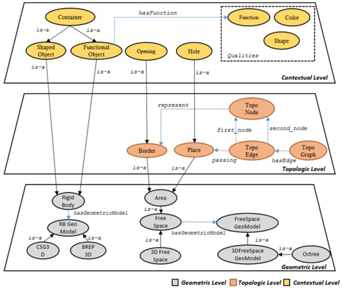
Figure 1 shows the general architecture of the proposed ontology with some key concepts and relations. A key objective of building ENVOn is to have a common vocabulary to be reused by different applications concerning manipulation tasks. The knowledge at each level should be easily extracted, updated, and reused by other domain ontologies. Therefore, we consider a modular architecture of the ontology model, where each level represents a module. In our design, three different modules are proposed:
- The geometry description module groups the concepts and relations related to the geometries of the rigid bodies and the free space module. RB Geo Model consists of two possible geometric models (i.e., CSG and BREP) of rigid bodies (Rigid Body) based on CAD. 3D Space Geo Model concerns the cell decomposition (Cell decomposition 3D) of the free space model (3D free space). Area represents a bounded volume of the 3D free space.
- The topology description module describes places (Place) and borders (Border) identified in the 3D simulation environment. It also illustrates their connectivity by constructing a topological graph (TopoGraph).
- The context description module provides the semantic description of rigid bodies (Rigid body), places, and borders. Such a kind of description includes the potential taxonomy (e.g., Container, Opening, Hole) and the related properties (Function, Color, Shape). We must note that this level of information heavily relies on the application (i.e., the manipulation task to be performed).
Fig. 1.
The general architecture of ENVOn.
Although the modular structure of the proposed ontology can facilitate its reusability by other domain ontologies, the initial work is performed on a single ontology file as an initial proposal. The ontology model is encoded in an OWL file and stored in the GitHub repository.44 Please note that Fig. 1 is only an example of the proposed ontology (previously introduced in [69]) and more detailed concepts will be given in the following sections.
4.1.The geometric description module
4.1.1.The common concepts and relations of the geometric description module
First, we defined some mathematical concepts that are the foundation of geometric information, e.g., the coordinate of Point, the direction of Axis, and the local reference frame of Rigid bodies. In Fig. 2, the conceptual map illustrates the main defined concepts.
Fig. 2.
The basic mathematical concepts for the geometric description.
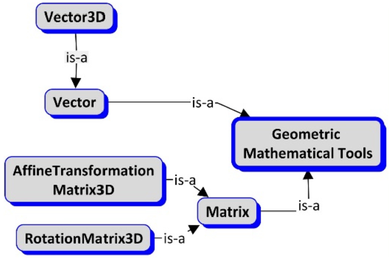
The Vector concept is formally defined as
- Vector3D is defined in the 3-dimensional Cartesian space, given by the x, y, and z coordinates and specified as three real numbers.
- RotationMatrix3D represents a rotation between two frames of reference in 3-dimensional Cartesian space (R3), any rotation can be given by a composition of rotations of the “x, y, z” axis, given in the form as:
AffineTransformationMatrix3D is a combination of rotation, translation, and scaling. It preserves the collinearity (i.e., points on a line remain collinear after transformation) and the proportions on the lines (i.e., the midpoint of the line remains the midpoint after transformation).
Table 2
Axioms – basic mathematical concepts
| Concept | Axiom |
| Vector3D | EquivalentTo: Vector and (x exactly 1 xsd:double) and (y exactly 1 xsd:double) and (z exactly 1 xsd:double) |
| RotationMatrix3D | EquivalentTo: Matrix and ( |
| Affine Transformation Matrix3D | EquivalentTo: Matrix and ( |
Second, we defined the geometric primitives that are considered as a set of elementary geometric objects [30], the combination of which may be used to represent varieties of complex 3D shapes (e.g., CAD parts). The common set of geometric primitives irrespective of any geometrical modelling techniques includes points, curves, and surfaces [50]. In order to further separate the geometric data from geometric modelling techniques as proposed by Kaiser et al. [35], volume should also be considered as a geometric primitive. Volume can not only be used to describe the primitive shapes in CSG (Constructive Solid Geometry) but also can be used to describe the geometry of any closed part of 3D Cartesian space. Figure 3 represents the geometric primitives using a conceptual map. These primitives are formally defined as follows:
- Point3D represents a position in a 3D Cartesian coordinate space. A Vector3D describes its position.
- Curve3D represents a path of a Point3D moving through a 3D Cartesian coordinate space.
- Surface3D represents a 2D subspace of a 3D Cartesian space.
- Volume3D represents the bounded volume by surface patches. A Volume3D might be formed by sweeping a certain Surface3D following a certain curve.
Curve3D, Surface3D, and Volume3D are abstract concepts. They can be further decorated with free parameters to define some pre-defined shapes. However, these concrete shapes need an AxisPlacement3D so that we can specify their orientation and location in 3D Cartesian space.
CircularCurve3D and CircularPlane3D are subtypes of Curve3D and Surface3D respectively and both are located some AxisPlacement3D. CircularCurve3D has a radius, whereas CircularPlane3D has a radius and is bounded by a CircularCurve3D curve. A CylindricalVolume is a Volume3D that has a sweeping plane, which is a CircularPlane3D, a sweeping direction (Vector3D), and a sweeping length. The formal definitions of these concepts are given in Table 3. It is to be noted that the geometrical primitives can be used for modelling both the rigid bodies model and the free space model.
Fig. 3.
The representation of geometric primitives.
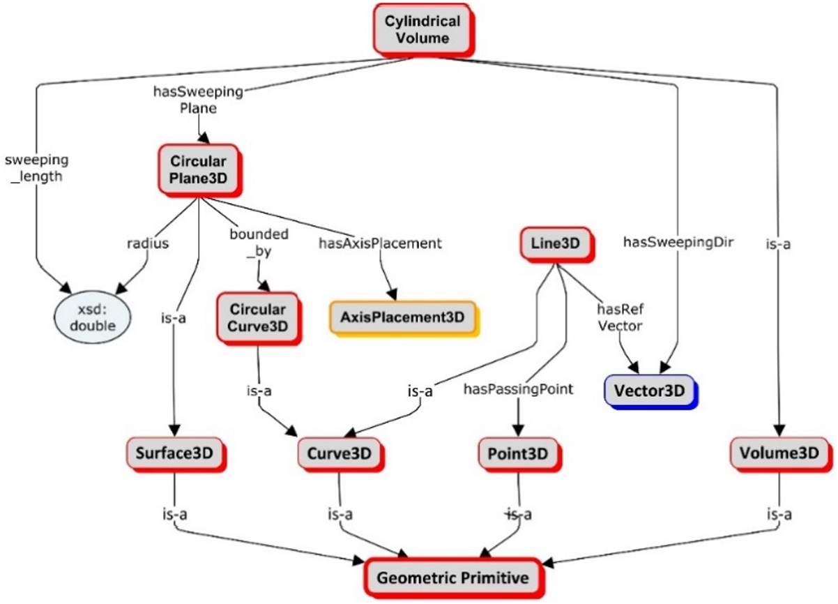
Table 3
Geometric primitives
| Concept | Axiom |
| Point3D | EquivalentTo: GeometricPrimitive and (hasPosition exactly 1 Vector3D) |
| Curve3D | SubClassOf: GeometricPrimitive |
| Surface3D | |
| Volume3D | |
| Line 3D | EquivalentTo: Curve3D and (hasRefVector exactly 1 Vector3D) and (hasPassingPoint exactly 1 Point3D) |
| CircularCurve3D | EquivalentTo: Curve3D and (hasAxisPlacement3D exactly 1 AxisPlacement3D) and (radius exactly 1 xsd:double) |
| CircularPlane3D | EquivalentTo: BoundedPlane3D and (hasAxisPlacement3D exactly 1 AxisPlacement3D) and (radius exactly 1 xsd:double) and (bounded_by exactly 1 CircularCurve3D) |
| CylindricalVolume | EquivalentTo: Volume3D and (hasSweepingPlane exactly 1 CircularPlane3D) and (hasSweepingDir exactly 1 Vector) and (sweeping_length exactly 1 xsd:double) |
Fig. 4.
The representation of supplementary geometric primitives.

Table 4
Some examples of axioms – supplementary geometric primitives
| Concept | Axiom |
| Axis3D | EquivalentTo: SupplementaryGeometricPrimitive and (hasPassingPoint exactly 1 Point3D) and (hasRefVector exactly 1 Vector3D) |
| AxisPlacement3D | EquivalentTo: SupplementaryGeometricPrimitive and (hasOrigin exactly 1 Point3D) and (hasRefXVector exactly 1 Vector3D) and (hasRefYVector exactly 1 Vector3D) and (hasRefZVector exactly 1 Vector3D) |
| 3D Cartesian ReferenceFrame | EquivalentTo: SupplementaryGeometricPrimitive and (hasAffineMatrix exactly 1 AffineTransformationMatrix3D or hasAxisPlacement3D exactly 1 AxisPlacement3D) |
| Oriented BoundingBox | EquivalentTo: SupplementaryGeometricPrimitive and (hasLocalReferenceFrame exactly 1 3DCartesianReferenceFrame) and (hasMinPoint exactly 1 Point3D) and (hasMaxPoint exactly 1 Point3D) |
Besides the geometric information about their composition, the rigid body model and the free space model also possibly contain other geometric properties, such as the central axis and the oriented bounding box. The supplementary geometric primitives present a list of geometric elements that do not compose the geometry of the rigid bodies model or the free space but assist in describing and manipulating them. Figure 4 presents four different concepts in a conceptual map, where the formal definitions are provided in Table 4. It is to be noted that AxisPlacement3D is also classified as a Supplementary Geometric Primitive as defined below.
- 3DCartesianReferenceFrame is a framework to perform measurements on location, distance, angle, etc, precisely and mathematically in a 3D Cartesian space. It is specified either by an AxisPlacement3D (an origin point, three orthogonal x, y, z axes), or an affine transformation regarding a world reference frame in 3D Cartesian space.
- Axis3D is a Line 3D to which a point, a curve, a surface, or a rigid body is measured, rotated, etc. For example, a symmetry axis of a surface indicates that each side of the axis is a mirror image.
- AxisPlacement3D identifies a reference frame in the 3D Cartesian space with a location point (the origin) and three orthogonal axes (i.e., x, y, and z-axis).
- OrientedBoundingBox is the minimum enclosing box for a point set of points (such as all points of a rigid body). It is defined by a minimum and a maximum point in the local reference frame.
4.1.2.The geometric representation of the rigid bodies model
In ENVOn ontology, the geometric descriptions of rigid bodies are built by closely following CAD models. Rather than semantically meaningless polygonal meshes, we adopt two main representations: the surface representation, and the volume representation. As discussed in Section 2, Boundary Representation (BREP) and Constructive Solid Geometry (CSG) are two formal schemes for surface and volume representation, respectively.
Concerning the geometric models of rigid bodies, we consider only simple geometries in the ENVOn ontology. For example, only simple kinds of Surface3D are used, whereas the NURBS (Non-uniform rational B-spline) surfaces [47] have not been considered at the current state of development. Moreover, besides the geometric models of rigid bodies, we introduce some common geometric properties related to rigid bodies, such as the central axis, the oriented bounding box, and origin. Figure 5 shows the main concepts and relations involved in the geometric representation of the rigid bodies model. The formal definitions of the concepts are given in Table 5.
- RigidBodyGeometricModel describes how a rigid body is geometrically composed. Two main modelling techniques: CSG and BREP, are adopted.
BREP3D concentrates on the boundary description of a rigid body (bounded_by attribute). Solid_Boundary describes the whole boundary of a rigid body. BREP_Face, topologically, represents an oriented 2D-manifold in 3D Cartesian space on the Solid_Boundary of a rigid body, and it is geometrically described by a Surface3D.
CSG3D describes the volume representation of a rigid body. The CSG3D of a rigid body is constructed using a set of standard primitives (CSG_Primitive) and Boolean operations among them. A CSG3D representation contains the top-level root CSG_composite (root_composite attribute).
- RigidBody represents any fixed or mobile obstacle in a 3D Cartesian space, with no deformation allowed. It contains one or more RigidBodyGeoemtric models to describe its geometric composition. A RigidBody has a Point3D as its origin to identify its position in the world reference frame, and a 3DCartesianReferenceFrame describes the local reference frame of the RigidBody; some geometric properties of the RigidBody are described in the local reference frame, such as the central axis (Axis3D), the oriented bounding box (OrientedBouningBox), the geometric models (RigidBodyGeometricModel) and the standard form. We consider the standard form of a RigidBody as the volume (Volume3D) bounded by the Solid_Boundary of the RigidBody.
Fig. 5.
The geometric representation for the rigid bodies model.
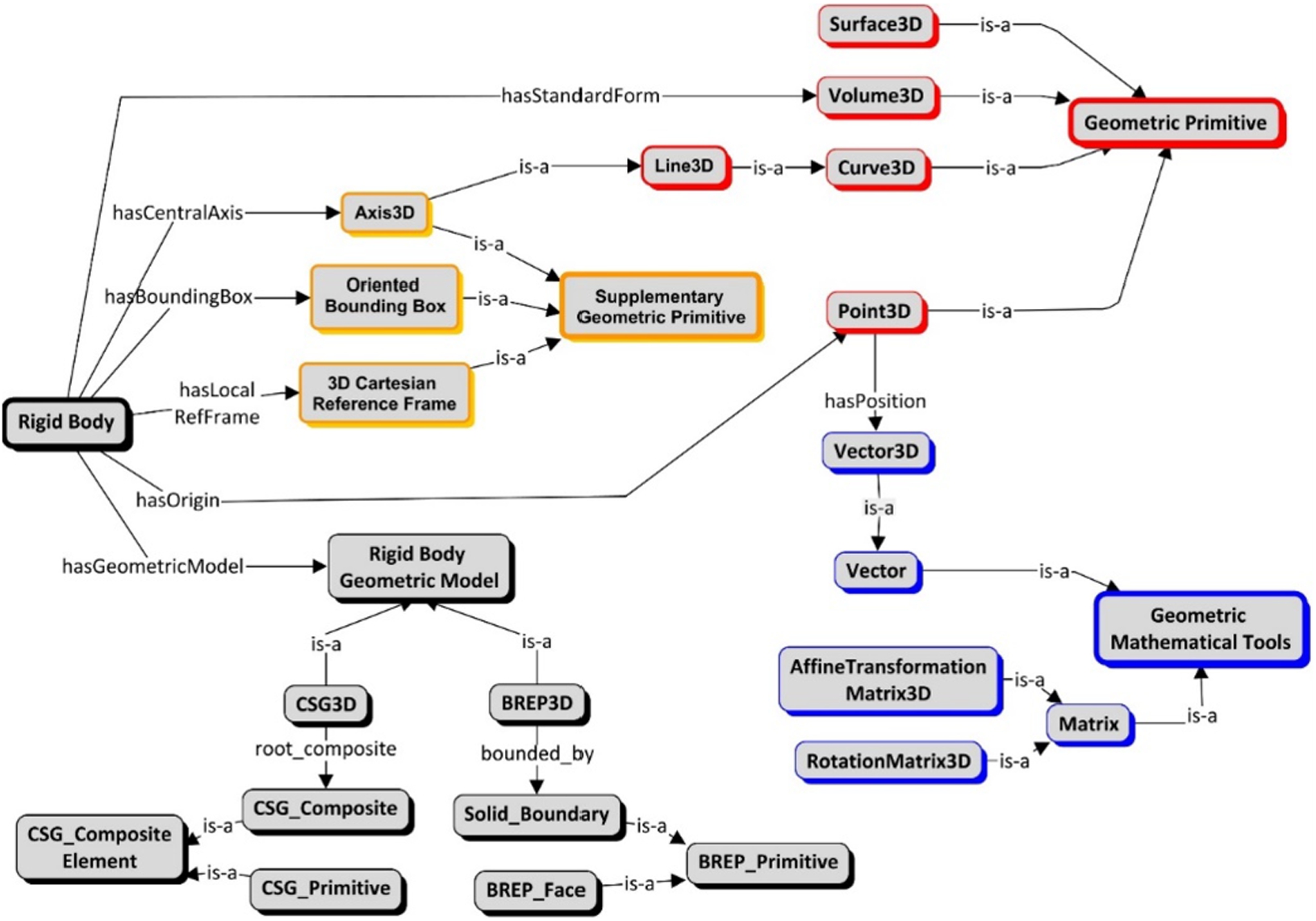
Table 5
Some examples of axioms – the rigid bodies model
| Concept | Axiom |
| CSG3D | EquivalentTo: RigidBodyGeometricModel and (root_composite exactly 1 CSG_Composite) |
| BREP3D | EquivalentTo: RigidBodyGeometricModel and (bounded_by exactly 1 Solid_Boundary) |
| Rigid Body | SubClassOf: (hasStandardForm exactly 1 Volume3D) and (hasCentralAxis exactly 1 Axis3D) and (hasBoundingBox exactly 1 OrientedBoundingBox) and (hasLocalReferanceFrame exactly 1 3DCartesianReferenceFrame) and (hasGeometricModel exactly 1 RigidBodyGeometricModel) and (hasOrigin exactly 1 Point3D) |
4.1.3.The geometric representation of the free space model
Fig. 6.
The geometric representation for the free space model.
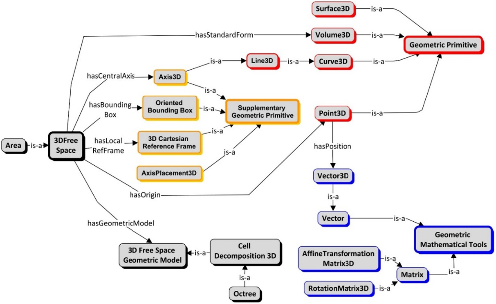
Table 6
Some examples of axioms – the free space model
| Concept | Axiom |
| Octree | EquivalentTo: CellDecomposition3D and (hasRoot exactly 1 OctreeNode) |
| 3DFreeSpace | SubClassOf: (hasStandardForm exactly 1 Volume3D) and (hasCentralAxis exactly 1 Axis3D) and (hasBoundingBox exactly 1 OrientedBoundingBox) and (hasLocalReferanceFrame exactly 1 3DCartesianReferenceFrame) and (hasGeometricModel exactly 1 3DFreeSpaceGeometricModel) and (hasOrigin exactly 1 Point3D) |
| Area | EquivalentTo: 3DFreeSpace and (isCloseBounded exactly 1 true) |
This work focuses on decomposing the free space model into a set of smaller geometric cells using cell decomposition techniques. Such a representation allows to characterize the geometric volume of the free space model, or even more, to easily find the part of the free space model (volume) in which a simulated task is interested, such as the part that belongs to a hole where a screw should be inserted. Like the rigid bodies model, the geometric representation of the free space model also contains other geometric properties besides its geometric model. Figure 6 shows the main concepts and relations involved in the geometric representation of the free space model. The formal definitions are given in Table 6.
- 3DFreeSpaceGeometricModel describes the geometric model of free space. We used a classical cell decomposition technique (Octree) [12].
- CellDecomposition3D is a method that decomposes a closed part of free space into several smaller geometric cells.
- Octree is a well-known volumetric representation in which 3D space is recursively divided into eight (hence “oct”) smaller volumes by planes parallel to the XY, YZ, and XZ coordinate system planes [23]. Since Octree only divides those geometric cells overlapped by obstacles, it is an unbalanced tree.
- OctreeNode: Each cell in the Octree is called an OctreeNode. Geometrically, it has a cuboid volume.
- 3DFreeSpace represents the obstacle-free part of the 3D Cartesian space. Similar to the RigidBody geometric representation, a 3DFreeSpace might have an origin (Point3D) to describe its position in the world reference frame, and a local reference frame (3DCartesianReferenceFrame) at this origin so that some geometric properties can be locally described, such as an oriented bounding box, a central axis, and a standard geometric form.
- Area represents a continuous closed part of 3DFreeSpace with a collection of common properties. Semantically, it can be further classified, such as kitchen, and corridor.
4.2.The topological description module
ENVOn needs to be able to answer competency questions related to localization and navigation, such as CQ11 to CQ14. For example, “Is a Place Y the right hole to insert a RigidBody X?”, and “Can a RigidBody X reach a Place Y from its current location?”. In order to answer such questions, the term Place, representing different locations of interest in an environment, needs to be tackled first. In the work of Cailhol et al. [12], the topological layer represents places, borders, and the topological relations between them (the border connects two places). Each place or border is associated with a set of geometrical cells in the geometrical layer. The topological model of the environment is static. The adjacency between the identified Borders allows the construction of a TopologicalGraph that can describe all possible connections to the Places. The topological description of the rigid bodies model (i.e., the connectivity of surfaces of a rigid body) is currently out of our scope and this study only concerns free space. Figure 7 shows the main concepts and relations of the topological description module. The formal definitions are given in Table 7.
- Place and Border: A Place represents a location in the environment. It is further classified regarding some concrete properties. For example, bedroom, kitchen, and bathroom are different Places specified by their functionality (i.e., sleeping, cooking, bathing respectively). A Border is the overlapped Area between two Places, such as the entrance between a room and a corridor.
- TopologicalNode is a basic element of the Topological Graph to represent a Border.
- TopologicalEdge connects two TopologicalNodes passing through a certain Place.
- TopologicalGraph describes the general connectivity of the free space model. It contains several TopologicalEdges to describe connections between different Borders.
Fig. 7.
The topological description module.
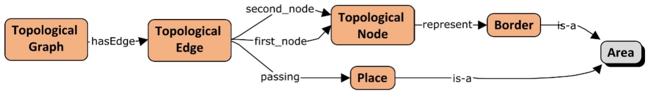
Table 7
Some examples of axioms – the topological description module
| Concept | Axiom |
| Place Border | SubClassOf: Area |
| Topological Node | SubClassOf: (represent exactly 1 Border) |
| Topological Edge | SubClassOf: (first_node exactly 1 TopologicalNode) and (second_node exactly 1 TopologicalNode) and (passing exactly 1 Place) |
| TopologicalGraph | SubClassOf: (hasEdge min 0 TopologicalEdge) |
4.3.The contextual description module
In applications specific to robotics and virtual reality, the simulated environment is rarely seen from the geometric point of view. The RigidBodies, Places, and Borders are identified with contextual semantics. For example, in an indoor household environment, RigidBodies can be a table, a door, or a booklet; the identified Places can be bedrooms or corridors; their Borders can be the entrances of bedrooms. In the construction of the contextual description module, these contextual semantics are also dependent on the specific application.
In the knowledge modelling literature, a distinction between ontologies and contexts has already been discussed in various kinds of research works [6,9,15,22,28,57]. In [68], such a distinction has been formalized as “ontologies are shared models of some domain that encodes a common view of different parties, whereas contexts are local and non-shared models that encode a party’s view on a particular domain”.
Fig. 8.
The semantic description module.
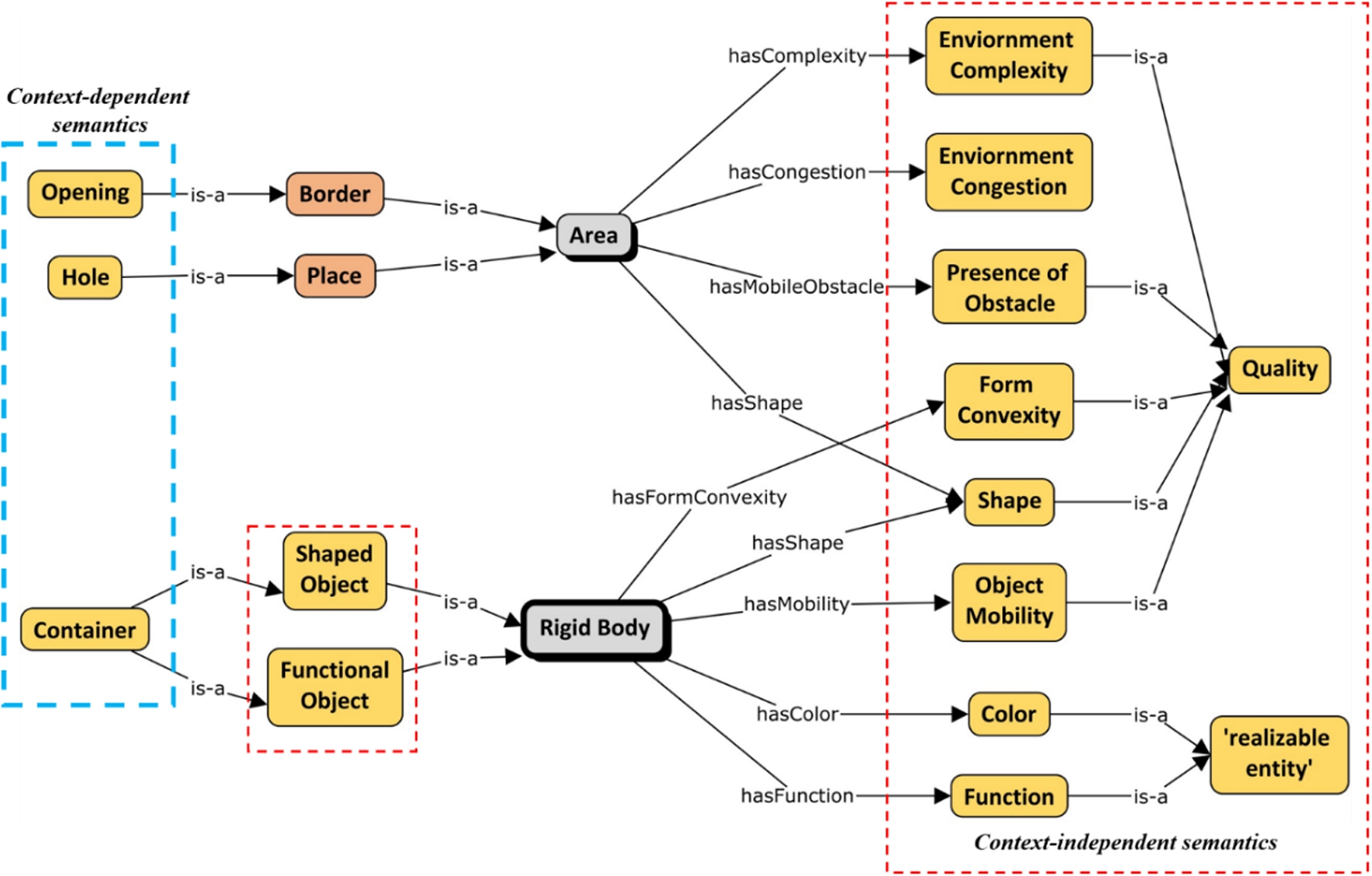
Following the idea of separating an ontology from its context, the contextual description module of the ontology of a 3D environment consists of two major parts: context-independent semantics and context-specific semantics. Sections 4.3.1 and 4.3.2 provide some formal definitions of the concepts of the semantic description module.
4.3.1.The context-independent semantics
The context-independent semantics are mostly the description of the characteristics of RigidBodies, Places and Borders (see Fig. 8). The characteristics are independent of context because their identities are recognized uniformly across different applications and measured with internationally standardized scales and units. Two types of characteristics are admitted in this model following the categorization of BFO [3]: Quality, which are apparent characteristics that do not depend on a process for their manifestation, and Realizable entity, which are characteristics that can only be exhibited through a certain realizing process. Below, we first describe some of the characteristics under Quality category and then some from Realizable entity category, which can be applied to either rigid bodies and free space specifically or both.
For example, the Shape and FormConvexity are types of Quality that define how a RigidBody looks like. Object Mobility defines whether a RigidBody is movable. The Function defines what a RigidBody can do (e.g., cooking, heating). Shape describes the appearance of an Area. Additionally, the Presence of Mobile Obstacle defines whether an Area contains mobile obstacles (i.e., Free, Intersected, or Blocked). The EnvironmentComplexity and EnvironmentCongestion describe whether an Area is difficult to cross. Some context-independent characteristics of RigidBodies may also be used as a clause to create new sub-categories under rigid bodies, such as ShapedObject, FunctionalObject. These categories can also be further defined according to the domain of simulations. For example, the construction domain [45] categorizes construction projects into three groups: building construction, infrastructure construction, and industrial construction.
Quality
- Shape quality is used to describe the geometric form of RigidBodies, Places, and Borders. Two subgroups, which are RegularShapeQuality and IrregularShapeQuality, are further obtained depending on whether their Shapes are regular or not. Typical RegularShapeQualities are RSQ_Cylinder, RSQ_TriangularPrism, RSQ_Cuboid.
- Form Convexity: If a RigidBody is convex, the line segment between any two points (in the interior or on the boundary of the RigidBody) should not go outside of the RigidBody. Otherwise, it is concavely formed.
- Object Mobility: A RigidBody can be fixed to the ground and cannot be moved during the whole simulation. Otherwise, it is a mobile obstacle that can be moved.
- Environment Congestion determines whether a Place or a Border provides enough space for the manipulated RigidBody to pass through. Wide and Narrow are two instances.
- Environment Complexity determines whether a Place or a Border is complex, e.g., filled with moving obstacles as a dynamic environment. Complex and Not complex are two instances.
- Presence of Mobile Obstacle is defined to specify whether a Place or a Border contains moving obstacles. Free means that no moving obstacle is inside of an Area, Intersected means that one or several moving obstacles is inside of an Area, Blocked means that an Area is completely covered by a moving obstacle.
Realizable entity
- Color of a RigidBody can only be exhibited through an optical lighting process. Classical colors are Black, White, Red, Blue, Green, Orange, Yellow.
- Function of a RigidBody is determined at the very beginning of the product design stage. However, it is not an intrinsic property of a RigidBody, and it can only be realized during a certain process. For example, the Fasten function of a screw can only be sensed in an assembly process of a product.
It is to be noted that Environment Complexity and Congestion can vary with time. e.g., a room may be crowded for some hours but empty later, and a corridor that is passable now becomes impassable once some items are dropped there. We do not however provide a tripartite relation to include time in the relations, e.g., hasComplexity, hasCongestion, and hasMobileObstance as such is not admitted by OWL. We leave it to the application developers to handle time while assigning qualities and functions to rigid bodies and areas. It is also to be noted that handling the change of qualities over time requires a certain commitment to either a 3D or 4D view of the world (different from a 3D environment) as such may result in different models.
4.3.2.The context-dependent semantics
The context-dependent semantics of RigidBodies, Places, and Borders relies heavily on the application that a simulated task handles. The concepts and relations are locally defined. The modelling of context-dependent semantics is a difficult activity as it varies among applications. Currently, context-dependent semantics is not the focus of this study. We only introduce Hole, Opening, and Container as local concepts (Context-dependent semantics in Table 8), so that the environment information of the two scenarios used in this paper (see Section 5.1) can be instantiated in the ontology.
Table 8
Some examples of axioms – the semantic description module
| Concept | Axiom |
| Hole | SubClassOf: Place and (hasCentralAxis exactly 1 Axis3D) |
| Opening | SubClassOf: Border and (hasOpeningDirection exactly 1 Vector3D) |
| ShapedObject | SubClassOf: RigidBody and (hasShape exactly 1 Shape) |
| FunctionalObject | SubClassOf: RigidBody and (hasFunction some Function) |
| Container | SubClassOf: ShapedObject and FunctionalObject and (hasSpaceInContainer exactly 1 Hole) and (hasOpening exactly 1 Opening) |
| Area | SubClassOf: (hasMobileObstacle exactly 1 PresenceOfObstacle) and (hasComplexity exactly 1 EnvironmentComplexity) and (hasCongestion exactly 1 EnvironmentCongestion) and (hasShape exactly 1 Shape) |
| Rigid Body | SubClassOf: (hasFormConvexity exactly 1 FormConvexity) and (hasColor exactly 1 Color) and (hasFunction exactly 1 Function) and (hasMobility exactly 1 ObjectMobility) and (hasShape exactly 1 Shape) |
5.Ontology validation
In this section, we focus on the validation of our approach in the context of the simulation of manipulation tasks to be performed under strong geometric constraints. In both scenarios, a particular object (a pen, or an object with a given shape) is to be moved from an initial configuration (in the robotic sense; in our case, a configuration of a manipulated object is defined by a 6D vector defining the 3D position and the 3D orientation) to a final one. Validating the scenarios consists in validating the feasibility of the corresponding motion planning queries.
The ontology verification evaluates whether an ontology is built correctly against ontology specification documents and correctly represents the intended model of the world aiming to conceptualize. In order to verify and validate the proposed ontology of the 3D environment for simulating manipulation tasks, we instantiate the ontology with real environment data of two scenarios and we examine whether the instantiated ontology can answer correctly the competency questions listed in Section 3. In this research work, SPARQL (SPARQL Protocol and RDF Query Language) is used as the query language to retrieve data from the ontology [67]. These SPARQL queries are available in the GitHub repository55 along with the instance data (ABox). More details about the added value of this ontology from a practical point of view (especially on path planning) can be found here in the work of Zhao et al. [70].
5.1.Simulation scenarios
The first case study concerns inserting a pen into a narrow penbox. Controlling the path planning process with geometric constraints provides a higher possibility of finding a collision-free trajectory for the insertion. The second case study introduces the shape attribute, which makes the insertion even harder.
The two scenarios chosen (insertion of a pen into a penbox, and shapes games for babies) are very relevant to validate our approach because of the following reasons
- They are very challenging for motion planning as they feature the manipulation of objects under very strong geometric constraints.
- They are representative of future industrial tasks to be simulated and validated as (a) they correspond to the manipulation of manufactured objects of standard shapes representative of parts to be assembled and (b) performing these tasks involves moving them through very narrow passages or inserting them in properly shaped holes, which is representative of generic tasks to be performed when (e.g.) assembling, disassembling, or performing maintenance in the real industrial systems.
- They are yet generic enough to ensure the objectivity of our validation.
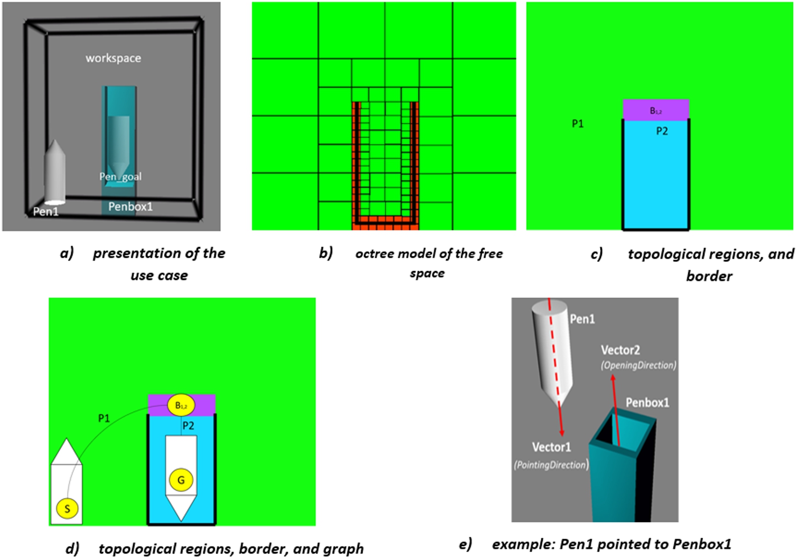
5.1.1.Scenario 1: Pen-Penbox insertion use case
The “workspace” of the simulation environment for pen-penbox insertion use case (Fig. 9-a) is the 3D Cartesian Space bounded by a line cube. Two obstacles can be found: Pen1 is a mobile obstacle and Penbox1 is a fixed obstacle. The objective of the task simulation is to insert Pen1 into Penbox1, where pen_goal is the configuration where the Pen1 should reach. The pen_goal is obtained by pre-sampling within Penbox1 (bounding box or P2).
Figure 9-a presents the use case (Pen1 at the start configuration, to be inserted into Penbox1 to reach the final configuration Pen_goal. Figure 9-b shows the octree representation of the free space. Figure 9-c and Fig. 9-d illustrate the construction of the topological level of the free space model from the geometric level of the free space model (i.e., cell decomposition of the workspace using an octree represented in 2D in Fig. 9-b). Figure 9-c shows the places (P1, P2) and border (B12) obtained from the octree by using region-growing algorithms [23] and Fig. 9-d illustrates the topological graph obtained in that case. The edges correspond to places P1 and P2, while nodes correspond to B12, and the start and goal configurations (respectively S and G); two nodes corresponding to S and G are added to the graph. Compared to the size of Pen1, P1 is enriched with the complexity attribute Free and P2 is Narrow. This allows applying geometric constraints differently in P1 and P2. Figure 9-e demonstrates an example when Pen1 is pointed to Penbox1 (i.e., Vector1 is against Vector2). This constraint will be used in computing a path from configuration S to configuration G when Pen1 is inserted into Penbox1.
Fig. 9.
A pen-penbox insertion use case.
5.1.2.Scenario 2: Shape embedding game
A more complex use case is inspired by the shape embedding game for children. Along with the geometric constraints in the pen-penbox insertion use case, it also requires matching the shape between the hole and the manipulated object.
The 3D environment for the simulation (see Fig. 10) constitutes a cuboid workspace cluttered with five rigid bodies (O1 to O5). O1 is fixed and O2 to O5 are moveable. Five different places (P1 to P5) are identified at the topological level of the 3D environment’s free space model. Semantically, P2 to P5 are defined as O1’s holes, and they respectively have the shape (Quality:Shape) of RSQ_Cylinder, RSQ_Cuboid, RSQ_PentagonPrism, and RSQ_Triangular Prism. O2 to O5 have the shape (Quality:Shape) of RSQ_Cylinder, RSQ_TriangularPrism, RSQ_Cuboid, and RSQ_PentagonPrism. The objective of the task simulation is to insert O2 to O5 into holes with the same shape (i.e. O2 into P2, O3 into P5, O4 into P3, and O5 into P4).
Fig. 10.
Shape embedding game.
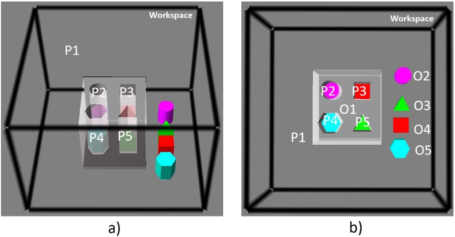
Fig. 11.
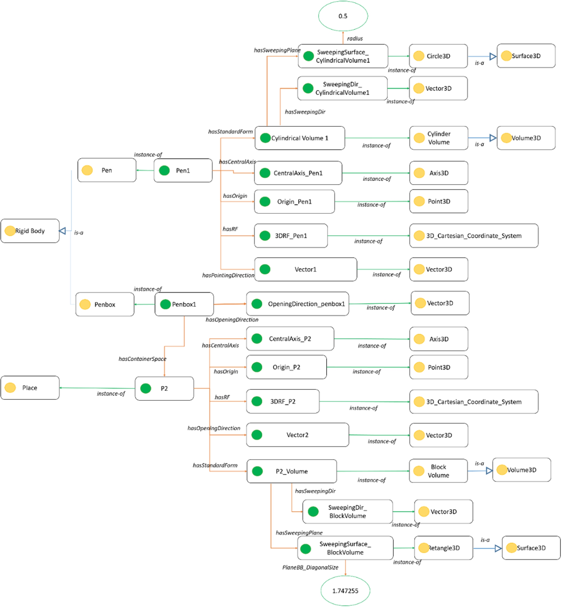
Instantiated ontology for 3D environment of the Pen-Penbox insertion scenario.
5.2.Verification and validation of the ontology of 3D environment: Scenario 1
Firstly, ENVOn is instantiated with the environment data of the pen-penbox insertion scenario (Fig. 11). For example, Pen1 is an instance of Pen and thus an instance of Rigid body. Pen1 has different object properties, such as CentralAxis_Pen1 (Axis3D) as its central axis, Vector1(Vector3D) as its pointing direction, and CylindricalVolume1 (CylindricalVolume) as its standard form. SweepingDir_CylindricalVolume1 (Vector3D) and SweepingPlane_CylindricalVolume1 (Circle3D) are respectively the sweeping direction and the sweeping plane of the Pen1’s Volume3D (CylindricalVolume1).
After instantiating the environment data in the ontology, we design and define some competency questions in Table 9 to validate the correctness of ENVOn. The evaluation also shows the facility of fast querying the environment data. For example,
- “What is the central axis of Pen1?” is straightforward to search for the Pen1’s central axis (i.e., CentralAxis_Pen1),
- “What is the opening direction of P2?” and “What is the pointing direction of Pen1?” query the direction (Vector3D) where P2 opens or Pen1 points, i.e., Vector1 and Vector2.
Table 9
Competency Questions – Querying geometric details
| Rigid body/place | Competency questions | Result |
| Pen1 (Type: Pen) | What is the central axis of Pen1? | CentralAxis_Pen1 |
| What are the sweeping plane and the sweeping direction of Pen1’s Volume? | SweepingDir_CylindricalVolume1 | |
| SweepingSurface_CylindricalVolume1 | ||
| What is the pointing direction of Pen1? | Vector1 (see Fig. 12) | |
| Penbox1 (Type: Penbox) | What is the opening direction of Penbox1? | OpeningDirection_penbox1 |
| P2 (Type: Place) | What is the opening direction of P2? | Vector2 |
| What are the sweeping plane and the sweeping direction of P2’s Volume? | SweepingDir_BlockVolume | |
| SweepingSurface_BlockVolume |
Fig. 12.
SPARQL query result – Pen1.
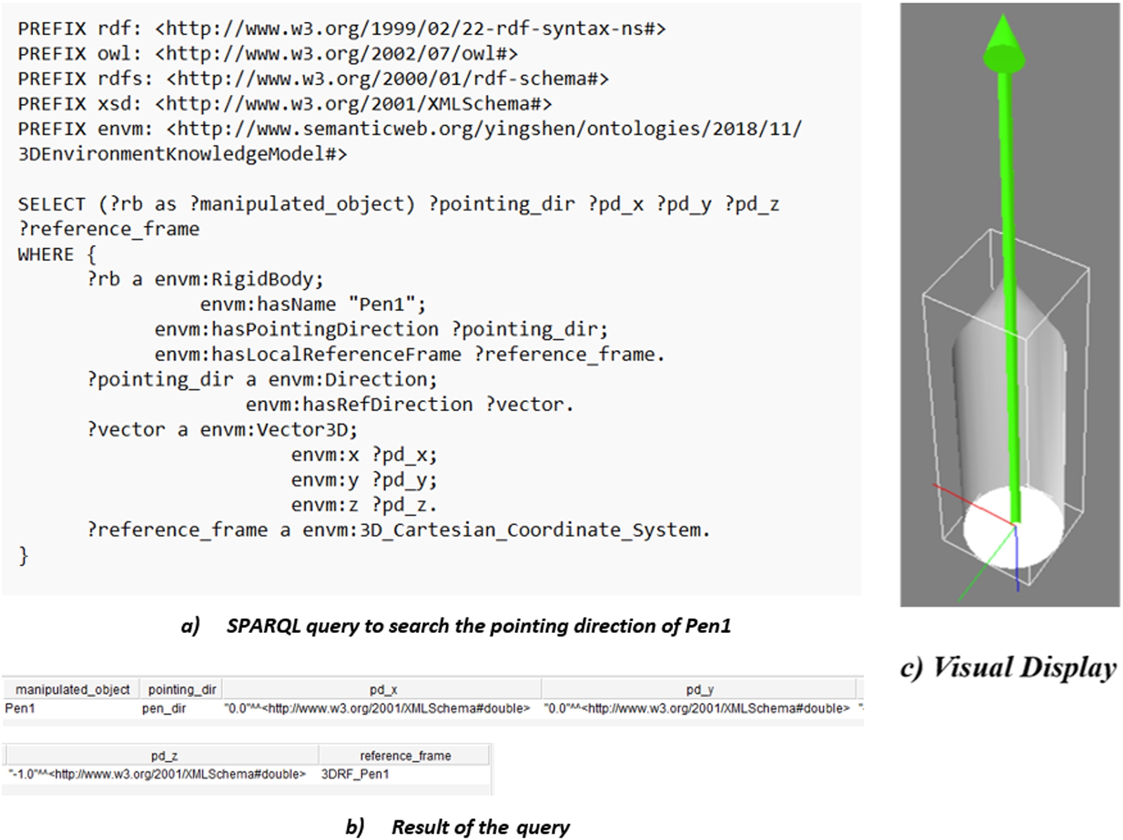
In Fig. 12-a, we demonstrate an example of SPARQL query to search for the pointing direction of Pen1 (?pointing_dir) and the local reference frame in which ?pointing_dir is defined. Figure 12-b and c respectively show the obtained results and their visual display in Virtools.
Table 10
Competency question – the possibility of inserting Pen1 into Penbox1
| Competency question | Result |
| Whether Pen1 can be inserted into P2? | 1 (meaning: Yes) |
| Pen1_SweepingPlane_Radius: 0.5 | |
| P2_SweepingPlane_DiagnalSize: 1.747255 |
Fig. 13.
The condition of whether Pen1 can be inserted into P2.
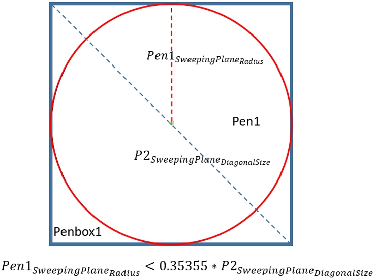
Fig. 14.
SPARQL query – the possibility of inserting a pen into a penbox.
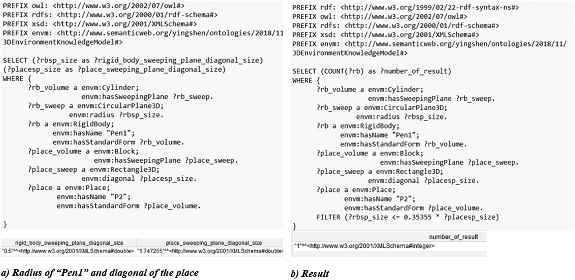
Moreover, to correctly insert Pen1 into Penbox1, we have to determine whether Pen1 can be inserted into Penbox1 first. In this scenario, it means whether Pen1 can be inserted into P2. The competency question of this issue is described in Table 10. P2 is a Place that has a standard form BlockVolume, and Pen1 is a Rigid Body that has a standard form CylindricalVolume. Both standard forms of P2 and Pen1 have the regular sweeping plane Retangle3D and Circle3D, i.e., the length of P2’s Retangle3D is equal and Pen1’s Circle3D is round. Therefore, the condition of whether Pen1 can be inserted into P2 is shown in Fig. 13.
In Fig. 14-a, we demonstrate an example of SPARQL query to search for the radius of the sweeping plane of Pen1 (?rigid_body_sweeping_plane_diagonal_size) and the diagonal size of the sweeping plane of P2 (?place_sweeping_plane_diagonal_size). In Fig. 14-b, we demonstrate an example of a SPARQL query to determine whether Pen1 can be inserted into P2. There is one result (?number_of_result = 1) so Pen1 can be inserted into Penbox1 in this use case.
Fig. 15.
Instantiated ontology for 3D environment of the shape embedding game scenario.
5.3.Verification and validation of the ontology of 3D environment: Scenario 2
First, the environment data of the shape embedding game scenario is firstly instantiated in the ontology of the 3D environment, as shown in Fig. 15. This data consists of the contextual, topologic, and geometric information of the 3D environment where the simulated task takes place.
Table 11
Competency Question – Query geometric details
| Rigid body | Competency question | Result |
| O3 | What is the central axis of O3? | CentralAxis_O3 |
| What is the pointing direction of O3? | Vector2 | |
| What are the sweeping plane and the sweeping direction of O3’s Volume? | SweepingDir_TriangularPrismVolume1 | |
| SweepingSurface_TriangularPrismVolume1 | ||
| What is the symmetric vector for the sweeping plane of P5’s Volume | Vector4 |
Table 12
Competency question – query geometric details (P5)
| Place | Competency question | Result |
| P5 | What is the central axis of P5? | CentralAxis_P5 |
| What is the opening direction of P5? | Vector1 | |
| What are the sweeping plane and the sweeping direction of P5’s Volume? | sweeping_dir_p5_volume | |
| sweeping_plane_p5 | ||
| What is the symmetric vector for the sweeping plane of P5’s Volume | Vector3 |
Fig. 16.
SPARQL query result – O3.
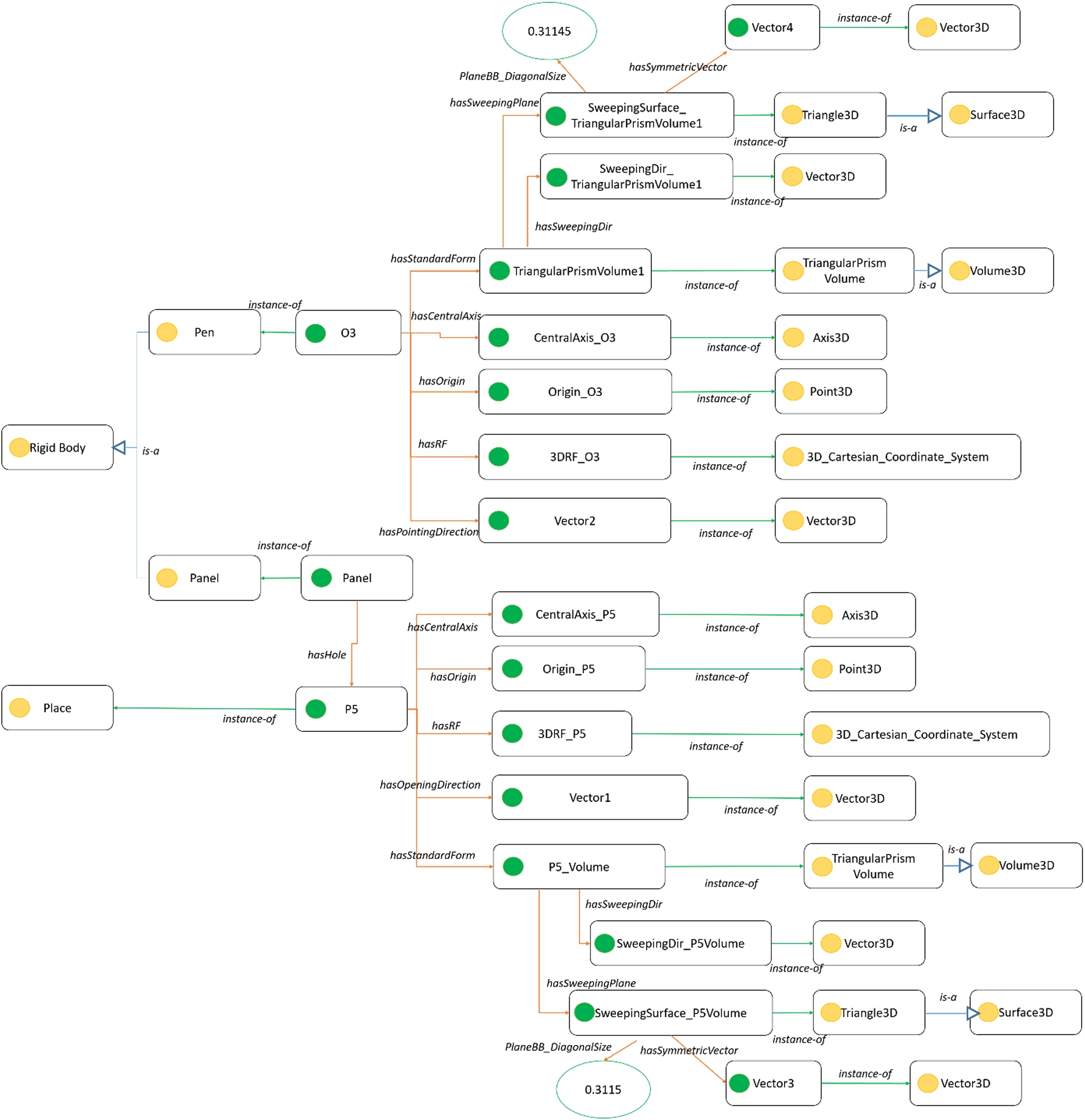
At the geometric level, different geometric properties of rigid bodies and places are captured. In the shaped game scenario, O3 is an instance of RigidBody and it has a pointing direction Vector2 (type: Vector3D), a local reference frame 3DRF_O3 (type: 3DCartesianReference Frame), an origin Origin_O3 (Point3D), a central axis CentralAxis_O3 (Axis3D), and a standard form TriangularPrismVolume1 (type: TriangularPrismVolume). O3’s standard form has a sweeping plane SweepingSurface_TriangularPrismVolume1 (type: Triangle3D) and has a sweeping direction SweepingDir_TriangularPrimsVolume1 (type: Vector3D). The sweeping plane’s diagonal size is 0.31145. P5 is an instance of place; it has a standard form P5_Volume (type: TriangularPrismVolume) with a different diagonal size 0.3115 of the sweeping plane SweepingSurface_P5Volume (type; TrangularPrismVolume). At the topological level, P1, P2, P3, P4, P5 are five different places constructed. P2–P5 has direct topological connections with P1. At the semantic level, O3 is further defined as an instance of Pen. P2–P5 are instances of Hole (they are narrow and have the shape of RSQ_Cylinder, RSQ_Block, RSQ_TriangularPrism, RSQ_PentagnonPrism, respectively).
We design and define some competency questions in Table 11 and 12. We can see from the obtained results that ENVOn can correctly answer these questions.
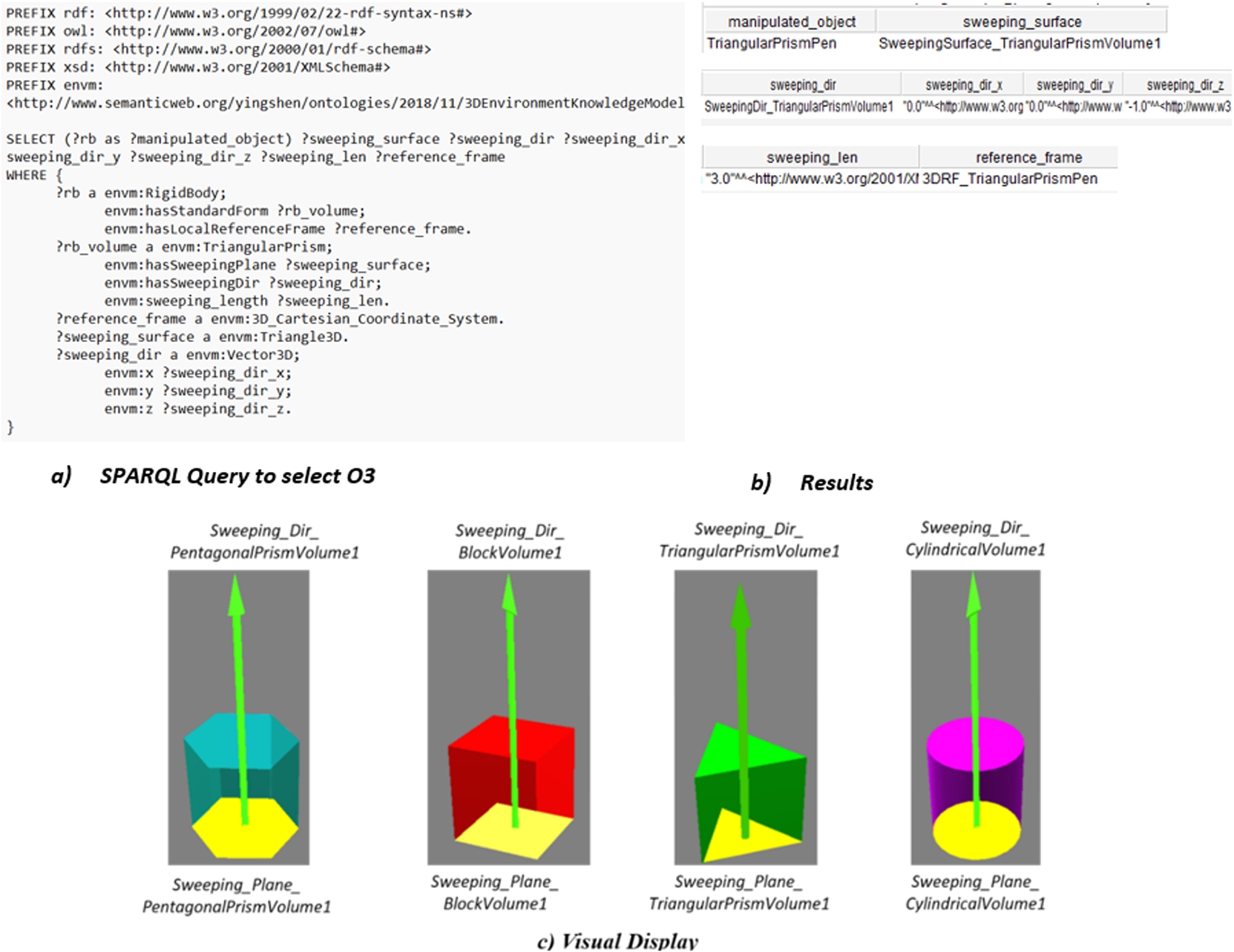
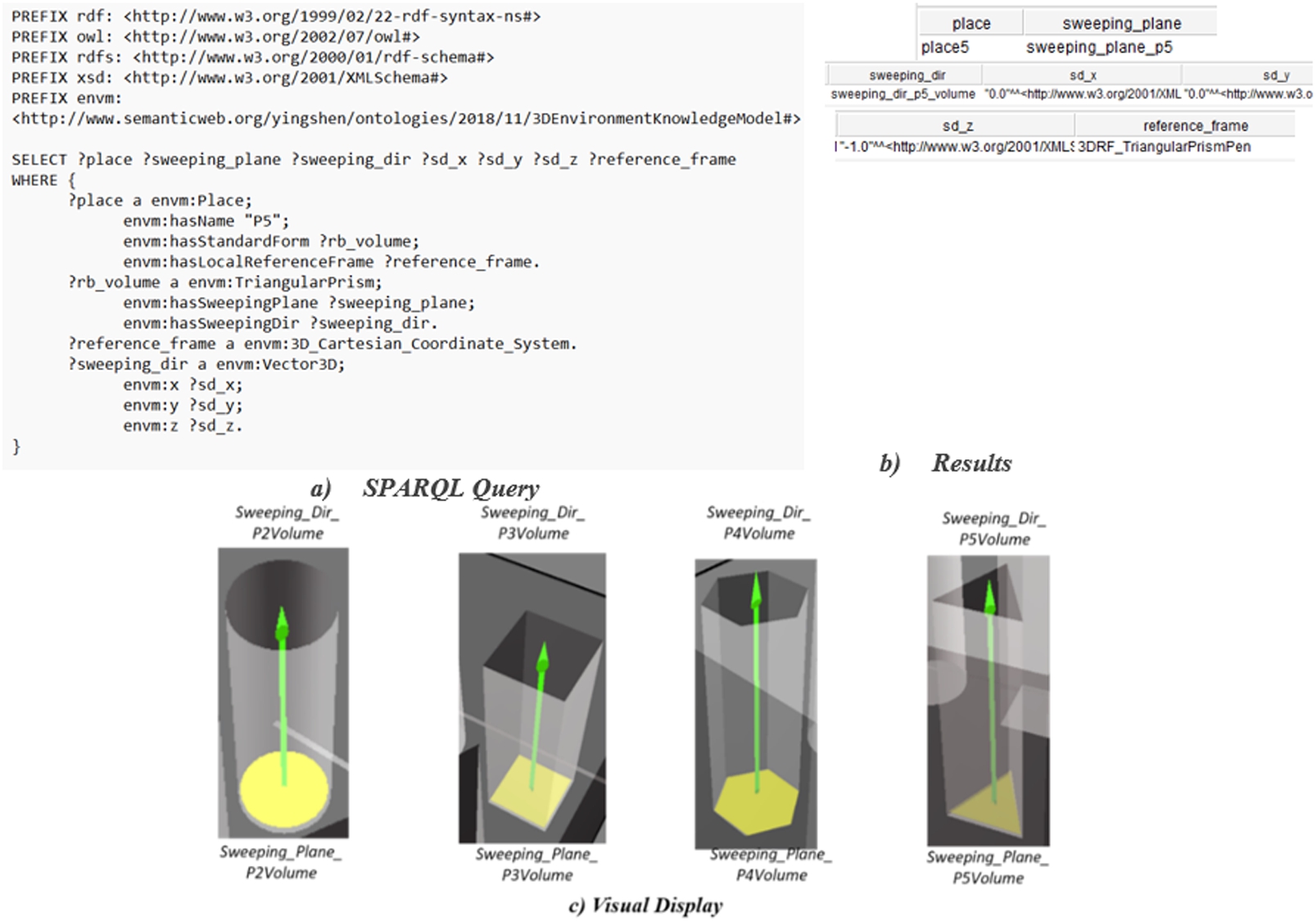
In Fig. 16 and Fig. 17, we demonstrate two examples of SPARQL queries to respectively search for the sweeping plane and the sweeping direction of O3 and P5, the obtained results, and their visual display in Virtools.
Fig. 17.
SPARQL query result – P5.
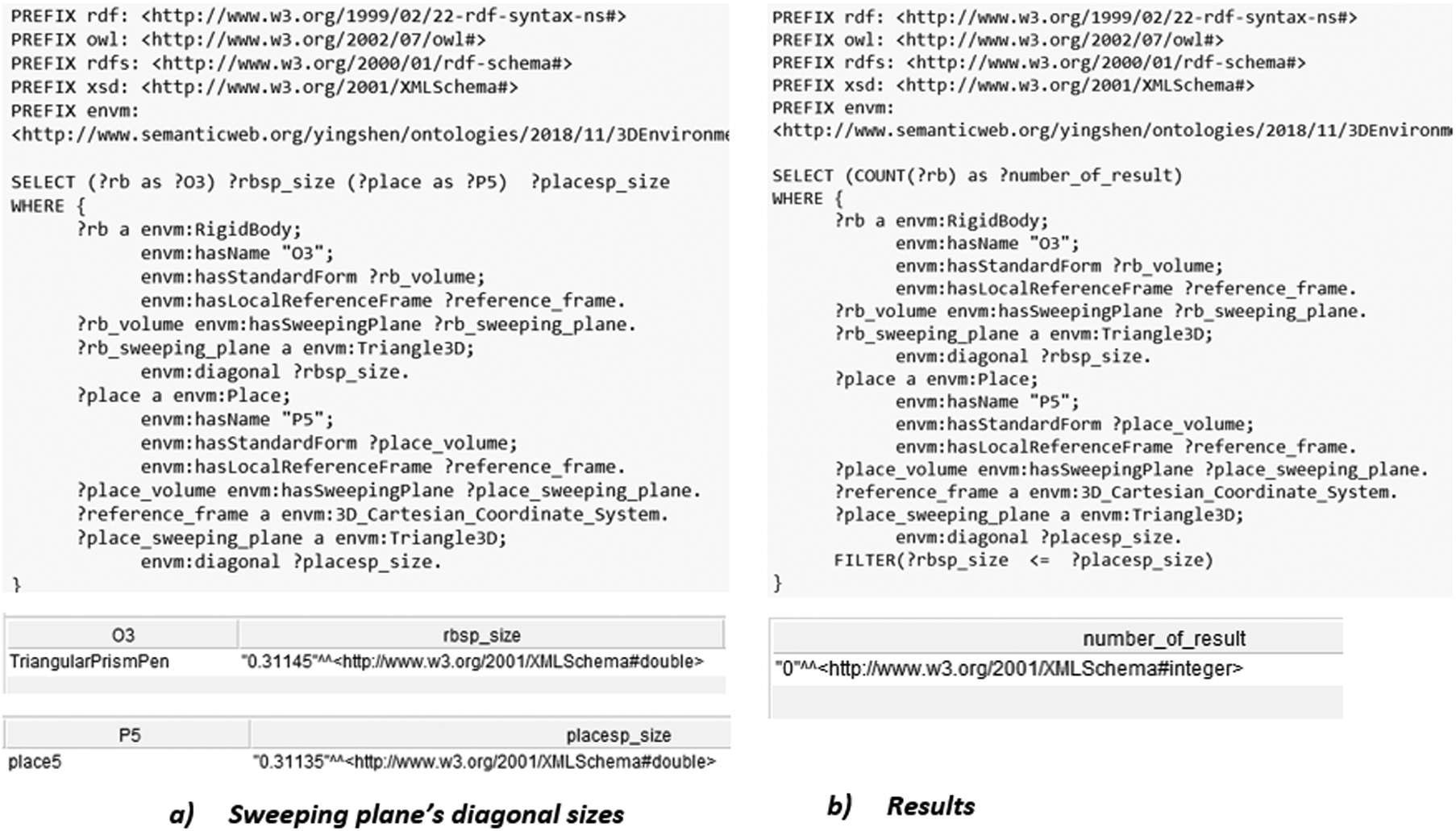
In Table 13, we propose two derivations: the first one specifies that the diagonal size of P5’s sweeping plane is 0.3115 and the second one 0.31135. A competency question is defined to check whether O3 can be inserted into P5. Because both O3 and P5 have standard forms TriangularPrism, the result relies on the diagonal size of O3’s and P5’s sweeping planes. Because the diagonal size of O3’s sweeping plane is smaller than the one of P5, O3 can be inserted into P5 in derivation 1. Otherwise, it is impossible to perform this primitive action (see derivation 2).
In Fig. 18-a, we demonstrate an example of a SPARQL query to search for the radius of the sweeping plane of O3 and the diagonal size of the sweeping plane of P5. In Fig. 18-b, we demonstrate an example of a SPARQL query to determine whether O3 can be inserted into P5. No result can be found (?number_of_result = 0) so O3 cannot be inserted into P5 in derivation 2.
6.Conclusion and future work
The primary contribution of this work is to link different levels of environment information using formal semantics. Such knowledge formalization allows answering semantically meaningful queries, such as “Does ObjectA fits HoleB?”. “What is the central axis of ObjectA?”. Moreover, to a certain extent, the knowledge reasoning capability using ontology (in terms of DL logics) allows a path planning system to make decisions on its own. For example, in answer to a given Insert primitive action to be performed, the path planning system can decide the most appropriate Hole to reach by exploring the environment ontology.
In the geometric description module, the geometries of rigid bodies (based on CAD models) have not taken into account all the criteria of the STEP standard. Currently, the geometry of the free space model considered only the octree decomposition of the simulation environment. In the topologic description module, “border as node, place as arc” is not necessarily the schema in all cases. In the semantic description module, the taxonomies of rigid bodies, places, and borders are very locally defined and the modelling of the relative locations between rigid bodies or between a rigid body and a place in 3D space should also be considered. Finally, different levels of abstraction (top-level, domain- and application-specific) should be considered in building an ontology in general. By aligning with the top-level ontology (e.g. BFO, DOLCE), the proposed ontology will become interoperable with other domain ontologies by making the correspondence between similar concepts have different names.
Table 13
Competency question – the possibility of inserting the triangular prism pen into P5
| Competency questions | Derivation | Result |
| Whether O3 can be inserted into P5? | Derivation 1 | 1 (meaning: Yes) |
| rbsp_size (diagonal length of sweeping plane of the rigid body): 0.31145 | ||
| placesp_size (diagonal length of sweeping plane of the place): 0.3115 | ||
| Derivation 2 | 0 (meaning: No) | |
| rbsp_size (diagonal length of sweeping plane of the rigid body): 0.31145 | ||
| placesp_size (diagonal length of sweeping plane of the place): 0.31135 |
Fig. 18.
SPARQL query – the possibility of inserting O3 into P5 (derivation 2).
One thing that draws our attention, during ontology development, is that not all environment information is suitable to be instantiated in an ontology, for example, polygonal models based on Delaunay triangulation that contains a large amount of raw data. The number of these points and lines might be large and they are sometimes semantically meaningless. Saving such geometric information in the ontology makes the knowledge base so overstaffed that the knowledge querying and reasoning can be slow, and even sometimes impossible. Indeed, such a kind of issue does not only happen in our ontology development. Rather, it is a common issue in the scientific community to build proper ontologies. Moreover, we expect that ENVOn can serve as a belief for the planning system so that the ontology can be updated whenever the belief changes: some things are added, and some things are deleted. For OWL and SWRL being monotonic in terms of logic, it is difficult to modify the already constructed ontology. Currently, our ontology has not taken the iterative environment update into account, and it only concerns the environment state now when a primitive action of manipulating an object takes place. Moreover, the calculation support using OWL and SWRL is limited [53]. In our research, only simple numerical comparisons are used, e.g., to find out whether a cylinder object can fit the cylinder hole by comparing its radius. Complex mathematical computations are not suitable to be modelled by logic but rather defined by external functions (e.g. Java), however, OWL and SWRL lack the mechanism to link the predicates with external functions (except simple built-in functions of SWRL).
On the contrary, the geometry of CAD models is semantically meaningful. For example, rather than thousands of meaningless triangular faces, the Cylindrical surface can be defined as a surface having an origin point, a central axis, and a radius. Similar semantically meaningful geometric information can be found everywhere in CAD models. However, the existing formats (e.g., STEP) of CAD models do not take advantage of the semantically meaningful data to allow knowledge querying and reasoning. Therefore, conceptualizing CAD models using ontology is worth researching. Similarly, ENVOn concepts are also required to be aligned to other standard and well-known ontologies, some of which are mentioned in Section 2, for increasing interoperability and compatibility. These alignments will also be included in future work.
Notes
Acknowledgements
This work is partially funded by the European Union’s Horizon 2020 project OntoCommons under Grant Agreement no. 958371.
References
[1] | A. Akbari, Muhayyuddin and J. Rosell, Knowledge-oriented task and motion planning for multiple mobile robots, J. Exp. Theor. Artif. Intell. 31: (1) ((2019) ), 137–162. doi:10.1080/0952813X.2018.1544280. |
[2] | F. Ameri, D. Sormaz, F. Psarommatis and D. Kiritsis, Industrial ontologies for interoperability in agile and resilient manufacturing, Int. J. Prod. Res. ((2021) ), 1–22. doi:10.1080/00207543.2021.1987553. |
[3] | R. Arp, B. Smith and A.D. Spear, Basic formal ontology at work, in: Building Ontologies with Basic Formal Ontology, The MIT Press, (2015) , pp. 1–19. doi:10.7551/mitpress/9780262527811.001.0001. |
[4] | R. Barbau et al., OntoSTEP: Enriching product model data using ontologies, Comput. Des. 44: (6) ((2012) ), 575–590. doi:10.1016/j.cad.2012.01.008. |
[5] | R. Battle and D. Kolas, Enabling the geospatial semantic web with Parliament and GeoSPARQL, Semant. Web 3: (4) ((2012) ), 355–370. |
[6] | D. Benslimane, A. Arara, G. Falquet, Z. Maamar, P. Thiran and F. Gargouri, in: Contextual Ontologies BT – Advances in Information Systems, (2006) , pp. 168–176. doi:10.1007/11890393_18. |
[7] | N. Blodow et al., Autonomous semantic mapping for robots performing everyday manipulation tasks in kitchen environments, in: 2011 IEEE/RSJ International Conference on Intelligent Robots and Systems, (2011) , pp. 4263–4270. doi:10.1109/IROS.2011.6094665. |
[8] | S. Borgo, A. Cesta, A. Orlandini and A. Umbrico, Knowledge-based adaptive agents for manufacturing domains, Eng. Comput. 35: (3) ((2019) ), 755–779. doi:10.1007/s00366-018-0630-6. |
[9] | P. Bouquet, F. Giunchiglia, F. Van Harmelen, V.U. Amsterdam, L. Serafini and F.B. Kessler, C-OWL: Contextualizing ontologies, (2003) . doi:10.1007/978-3-540-39718-2. |
[10] | R.A. Brooks and T. Lozano-Perez, A subdivision algorithm in configuration space for findpath with rotation, IEEE Trans. Syst. Man. Cybern. SMC-15: (2) ((1985) ), 224–233. doi:10.1109/TSMC.1985.6313352. |
[11] | S. Cailhol, P. Fillatreau, J.-Y. Fourquet and Y. Zhao, A hierarchic approach for path planning in virtual reality, Int. J. Interact. Des. Manuf. 9: (4) ((2015) ), 291–302. doi:10.1007/s12008-015-0272-5. |
[12] | S. Cailhol, P. Fillatreau, Y. Zhao and J. Fourquet, Multi-layer path planning control for the simulation of manipulation tasks: Involving semantics and topology, Robot. Comput. Integr. Manuf. 57: ((2019) ), 17–28. doi:10.1016/j.rcim.2018.10.010. |
[13] | S. Cailhol, P. Fillatreau, Y. Zhao and J.-Y. Fourquet, Multi-layer path planning control for the simulation of manipulation tasks: Involving semantics and topology, Robot. Comput. Integr. Manuf. 57: ((2019) ), 17–28. doi:10.1016/j.rcim.2018.10.010. |
[14] | S. Cambon, R. Alami and F. Gravot, A hybrid approach to intricate motion, manipulation and task planning, Int. J. Rob. Res. 28: (1) ((2009) ), 104–126. doi:10.1177/0278364908097884. |
[15] | V. Challam, S. Gauch and A. Chandramouli, Contextual search using ontology-based user profiles, (2007) . |
[16] | A.L. Clark and S.M. Staley, STEP AP203 data exchange study, in: Proceedings of the Third ACM Symposium on Solid Modeling and Applications, (1995) , pp. 213–224. doi:10.1145/218013.218063. |
[17] | J.P. Dandois and E.C. Ellis, High spatial resolution three-dimensional mapping of vegetation spectral dynamics using computer vision, Remote Sens. Environ. 136: ((2013) ), 259–276. doi:10.1016/j.rse.2013.04.005. |
[18] | G. Dedeoglu, M.J. Mataric and G.S. Sukhatme, Incremental online topological map building with a mobile robot, (1999) , pp. 129–139. doi:10.1117/12.369248. |
[19] | D. Demyen and M. Buro, Efficient triangulation-based pathfinding, in: Proc. Natl. Conf. Artif. Intell., Vol. 1: , (2006) , pp. 942–947. |
[20] | M. Devy, R. Chatila, P. Fillatreau, S. Lacroix and F. Nashashibi, On autonomous navigation in a natural environment, Rob. Auton. Syst. 16: (1) ((1995) ), 5–16. doi:10.1016/0921-8890(95)00028-E. |
[21] | M. Diab, A. Akbari, M. Ud Din and J. Rosell, PMK – a knowledge processing framework for autonomous robotics perception and manipulation, Sensors (Basel) 19: (5) ((2019) ). doi:10.3390/s19051166. |
[22] | A. Firat and S. Madnick, Information integration using contextual knowledge and ontology merging, (2003) . |
[23] | R.B. Fisher et al., Dictionary of Computer Vision and Image Processing, John Wiley & Sons, Ltd, Chichester, UK, (2016) . |
[24] | D. Flavigne and M. Taïx, Improving motion planning in weakly connected configuration spaces, in: 2010 IEEE/RSJ International Conference on Intelligent Robots and Systems, (2010) , pp. 5900–5905. doi:10.1109/IROS.2010.5650612. |
[25] | C. Galindo, J.-A. Fernández-Madrigal, J. González and A. Saffiotti, Robot task planning using semantic maps, Rob. Auton. Syst. 56: (11) ((2008) ), 955–966. doi:10.1016/j.robot.2008.08.007. |
[26] | C. Galindo, A. Saffiotti, S. Coradeschi, P. Buschka, J.A. Fernandez-Madrigal and J. Gonzalez, Multi-hierarchical semantic maps for mobile robotics, in: 2005 IEEE/RSJ International Conference on Intelligent Robots and Systems, (2005) , pp. 2278–2283. doi:10.1109/IROS.2005.1545511. |
[27] | M. Grüninger and M.S. Fox, Methodology for the design and evaluation of ontologies, (1995) . |
[28] | I. Gursel Dino et al., Contextual ontology support as external knowledge representation for building information modelling, (2009) . |
[29] | S.C. Hirtle and J. Jonides, Evidence of hierarchies in cognitive maps, Mem. Cognit. 13: (3) ((1985) ), 208–217. doi:10.3758/BF03197683. |
[30] | C.M. Hoffmann, Geometric and Solid Modeling, Morgan Kaufmann Pub., (1989) . |
[31] | I. Hong Suh, G. Hyun Lim, W. Hwang, H. Suh, J.-H. Choi and Y.-T. Park, Ontology-based multi-layered robot knowledge framework (OMRKF) for robot intelligence, in: 2007 IEEE/RSJ International Conference on Intelligent Robots and Systems, (2007) , pp. 429–436. doi:10.1109/IROS.2007.4399082. |
[32] | R. Iacob, D. Popescu and P. Mitrouchev, Assembly/disassembly analysis and modeling techniques: A review, Strojniški Vestn. –J. Mech. Eng. 58: (11) ((2012) ), 653–664. doi:10.5545/sv-jme.2011.183. |
[33] | S. Jeong, D.M. Wegner and S. Noh, Validation of an ontology-based approach for enhancing human simulation in general assembly environments, in: WCE 2010 – World Congr. Eng. 2010, Vol. 3: , (2010) , pp. 2313–2317. |
[34] | L.P. Kaelbling and T. Lozano-Perez, Hierarchical task and motion planning in the now, in: 2011 IEEE International Conference on Robotics and Automation, (2011) , pp. 1470–1477. doi:10.1109/ICRA.2011.5980391. |
[35] | A. Kaiser, J.A. Ybanez Zepeda and T. Boubekeur, A survey of simple geometric primitives detection methods for captured 3D data, Comput. Graph. Forum 38: (1) ((2019) ), 167–196. doi:10.1111/cgf.13451. |
[36] | D. Kortenkamp and T. Weymouth, Topological mapping for mobile robots using a combination of sonar and vision sensing, in: Proc. Natl. Conf. Artif. Intell., Vol. 2: , (1994) , pp. 979–984. |
[37] | B. Kuipers, J. Modayil, P. Beeson, M. MacMahon and F. Savelli, Local metrical and global topological maps in the hybrid spatial semantic hierarchy, in: IEEE International Conference on Robotics and Automation, 2004. Proceedings, ICRA’04, Vol. 5: , (2004) , pp. 4845–4851. doi:10.1109/ROBOT.2004.1302485. |
[38] | N. Ladeveze, J.-Y. Fourquet and B. Puel, Interactive path planning for haptic assistance in assembly tasks, Comput. Graph. 34: (1) ((2010) ), 17–25. doi:10.1016/j.cag.2009.10.007. |
[39] | F. Leoty, P. Fillatreau and B. Archimede, Path planning control using high abstraction level environment model and industrial task-oriented knowledge, in: 2021 IEEE International Workshop of Electronics, Control, Measurement, Signals and Their Application to Mechatronics (ECMSM), (2021) , pp. 1–6. doi:10.1109/ECMSM51310.2021.9468850. |
[40] | Lozano-Perez, Spatial planning: A configuration space approach, IEEE Trans. Comput. C-32: (2) ((1983) ), 108–120. doi:10.1109/TC.1983.1676196. |
[41] | Z. Márton, N. Blodow, M.E. Dolha, M. Tenorth, R.B. Rusu and M. Beetz, Autonomous mapping of kitchen environments and applications, (2008) . |
[42] | T.P. McNamara, Mental representations of spatial relations, Cogn. Psychol. 18: (1) ((1986) ), 87–121. doi:10.1016/0010-0285(86)90016-2. |
[43] | Ó.M. Mozos, P. Jensfelt, H. Zender, G.-J.M. Kruijff and W. Burgard, From labels to semantics: An integrated system for conceptual spatial representations of indoor environments for mobile robots, in: Proc. the International Conference on Intelligent Robots Systems Workshops, ((2007) ). |
[44] | A. Nüchter and J. Hertzberg, Towards semantic maps for mobile robots, Rob. Auton. Syst. 56: (11) ((2008) ), 915–926. doi:10.1016/j.robot.2008.08.001. |
[45] | A. Olivares-Alarcos et al., A review and comparison of ontology-based approaches to robot autonomy, Knowl. Eng. Rev. 34: ((2019) ), 1–29. doi:10.1017/S0269888919000237. |
[46] | A. Perzylo, N. Somani, M. Rickert and A. Knoll, An ontology for CAD data and geometric constraints as a link between product models and semantic robot task descriptions, in: IEEE International Conference on Intelligent Robots and Systems, (2015) , pp. 4197–4203. doi:10.1109/IROS.2015.7353971. |
[47] | L. Piegl and W. Tiller, Curve and surface constructions using rational B-splines, Comput. Des. 19: (9) ((1987) ), 485–498. doi:10.1016/0010-4485(87)90234-X. |
[48] | M.J. Pratt, Introduction to ISO 10303 – the STEP standard for product data exchange, J. Comput. Inf. Sci. Eng. 1: (1) ((2001) ), 102–103. doi:10.1115/1.1354995. |
[49] | A. Pronobis, O. Martínez Mozos, B. Caputo and P. Jensfelt, Multi-modal semantic place classification, Int. J. Rob. Res. 29: (2–3) ((2010) ), 298–320. doi:10.1177/0278364909356483. |
[50] | G. Roth and M.D. Levine, Geometric primitive extraction using a genetic algorithm, in: Proceedings 1992 IEEE Computer Society Conference on Computer Vision and Pattern Recognition, (1992) , pp. 640–643. doi:10.1109/CVPR.1992.223120. |
[51] | R.B. Rusu, Semantic 3D object maps for everyday manipulation in human living environments, KI – Künstliche Intelligenz 24: (4) ((2010) ), 345–348. doi:10.1007/s13218-010-0059-6. |
[52] | H. Samet, The quadtree and related hierarchical data structures, ACM Comput. Surv. 16: (2) ((1984) ), 187–260. doi:10.1145/356924.356930. |
[53] | A. Sánchez-Macián, E. Pastor, J.E. de López Vergara and D. López, Extending SWRL to enhance mathematical support, (2007) , pp. 358–360. |
[54] | M.M.M. Sarcar, K. Mallikarjuna Rao and L.K. Narayan, Computer Aided Design and Manufacturing, PHI Learning Pvt. Ltd., (2008) . |
[55] | A. Sarkar and D. Šormaz, On semantic interoperability of model-based definition of product design, Procedia Manuf. 38: ((2019) ), 513–523. doi:10.1016/j.promfg.2020.01.065. |
[56] | S. Srivastava, E. Fang, L. Riano, R. Chitnis, S. Russell and P. Abbeel, Combined task and motion planning through an extensible planner-independent interface layer, in: 2014 IEEE International Conference on Robotics and Automation (ICRA), (2014) , pp. 639–646. doi:10.1109/ICRA.2014.6906922. |
[57] | H. Stuckenschmidt, F. Van Harmelen, V.U. Amsterdam, L. Serafini, F.B. Kessler and P. Bouquet, Using C-OWL for the alignment and merging of medical ontologies, (2004) , no. May. |
[58] | J.J. Sylvester, Sketch of a memoir on elimination, transformation, and canonical forms, Cambridge Dublin Math. J. 6: ((1851) ), 186–200. |
[59] | M. Tenorth and M. Beetz, KNOWROB – knowledge processing for autonomous personal robots, in: IEEE/RSJ International Conference on Intelligent Robots and Systems, (2009) . doi:10.1109/IROS.2009.5354602. |
[60] | W. Terkaj and P. Pauwels, A method to generate a modular ifcOWL ontology, in: CEUR Workshop Proc. Vol. 2050: , ((2017) ). |
[61] | Torralba, Murphy, Freeman and Rubin, Context-based vision system for place and object recognition, in: Proceedings Ninth IEEE International Conference on Computer Vision, Vol. 239: , (2003) , pp. 273–280, vol. 1. doi:10.1109/ICCV.2003.1238354. |
[62] | I. Ulrich and I. Nourbakhsh, Appearance-based place recognition for topological localization, in: Proceedings 2000 ICRA. Millennium Conference. IEEE International Conference on Robotics and Automation. Symposia Proceedings (Cat. No. 00CH37065), Vol. 2: , pp. 1023–1029. doi:10.1109/ROBOT.2000.844734. |
[63] | A. Vasquez, A. Dapogny, K. Bailly and V. Perdereau, Sequential recognition of in-hand object shape using a collection of neural forests, in: 2017 IEEE/RSJ International Conference on Intelligent Robots and Systems (IROS), (2017) , pp. 3081–3086. doi:10.1109/IROS.2017.8206148. |
[64] | E. Vassev and M. Hinchey, Knowledge representation for cognitive robotic systems, in: 2012 IEEE 15th International Symposium on Object/Component/Service-Oriented Real-Time Distributed Computing Workshops, (2012) , pp. 156–163. doi:10.1109/ISORCW.2012.36. |
[65] | P. Viswanathan, T. Southey, J. Little and A. Mackworth, Place classification using visual object categorization and global information, in: 2011 Canadian Conference on Computer and Robot Vision, (2011) , pp. 1–7. doi:10.1109/CRV.2011.8. |
[66] | J. Vogel and B. Schiele, A semantic typicality measure for natural scene categorization, (2004) , pp. 195–203. |
[67] | D. Wiśniewski, J. Potoniec, A. Ławrynowicz and C.M. Keet, Analysis of ontology competency questions and their formalizations in SPARQL-OWL, J. Web Semant. 59: ((2019) ), 100534. doi:10.1016/j.websem.2019.100534. |
[68] | D. Xu, M.H. Karray and B. Archimède, A semantic-based decision support platform to assist products’ eco-labeling process, Ind. Manag. Data Syst. 117: (7) ((2017) ), 1340–1361. doi:10.1108/IMDS-09-2016-0405. |
[69] | H. Zender, O. Martínez Mozos, P. Jensfelt, G.-J.M. Kruijff and W. Burgard, Conceptual spatial representations for indoor mobile robots, Rob. Auton. Syst. 56: (6) ((2008) ), 493–502. doi:10.1016/j.robot.2008.03.007. |
[70] | Y. Zhao, P. Fillatreau, M.H. Karray and B. Archimede, An ontology-based approach towards coupling task and path planning for the simulation of manipulation tasks, in: 2018 IEEE/ACS 15th International Conference on Computer Systems and Applications (AICCSA), (2018) , pp. 1–8. doi:10.1109/AICCSA.2018.8612805. |


