
Approaches to high-density storage experiments with in-situ production and detection of ultracold neutrons
Abstract
Low counting statistics is one of the most important challenges in modern experiments with ultracold neutrons (UCN). UCN densities in superthermal sources based on superfluid helium are normally much higher than those after UCN delivery to ex-situ volumes. Therefore, and due to the vanishing neutron absorption of 4He, storage-based experiments performed in-situ promise significant sensitivity gains. Scalable measurements offer a promising path to simultaneously address the inefficient use of cold neutron beams as precursors for UCN production in 4He, by recuperating the unused beam fraction, and confront the practical challenges of large-scale UCN infrastructure. We suggest strategies for the development of modular cryogenic cells, propose a novel approach for in-situ UCN detection, and discuss the ultimate statistical reach of such a multiplexed experiment for measuring the neutron’s permanent electric dipole moment (EDM). While dedicated research and development are needed to evaluate the feasibility for many requirements, a neutron EDM measurement with sensitivity well beyond
1.Introduction
Since the very first publication [61] discussing the experimental possibility of trapping neutrons, it has been recognized that the principal difficulty lies in obtaining large numbers. While confining energy barriers in the range of
Yet the low numbers of UCN obtainable today remain the greatest obstacle to improved measurements, despite enormous progress in the more than 50 years since UCN were first detected in experiments [32,48]. While the time constants for UCN storage have in some instances already approached
2.UCN production by superthermal conversion of pre-moderated neutrons
Present-day UCN sources already achieve in-situ densities ranging up to
A very successful approach to high-flux UCN production is “spectral transformation” of the low-energy tail from cold neutron sources, notably in the Institut Laue–Langevin’s neutron turbine PF2 [51]. While not increasing the phase-space density, this type of source does provide strong UCN beams – thus enabling other classes of experiments to operate in “flow-through” mode: i.e., those that can accept shorter dwell-times. Unfortunately, severe technical challenges accompany the production of very high UCN densities by moderation: very low moderator temperatures and/or extremely high neutron flux are needed in order to amplify the weak low-energy tail of the moderated spectrum. In any case the radiological environment of such moderators cannot support human access or low-background precision experiments in-situ.
To obtain high stored UCN densities, it is more effective to exploit non-equilibrium “conversion” processes that can increase phase-space density through dissipation. In such “superthermal” sources [21] cold neutrons can lose most of their energy and momentum within very few scattering events, with this energy loss “overshooting” the thermal equilibrium obtainable in large moderators [49]. Resulting excitations of the convertor medium (e.g., phonons) are continuously removed by cooling; this mechanism is illustrated for superfluid 4He in Fig. 1.
Fig. 1.
Superthermal UCN production in superfluid 4He. The plot (left) overlays the dispersion relations for free neutrons, and for superfluid 4He at zero pressure using data from reference [16]. Neutrons with momentum
![Superthermal UCN production in superfluid 4He. The plot (left) overlays the dispersion relations for free neutrons, and for superfluid 4He at zero pressure using data from reference [16]. Neutrons with momentum ℏk and energy E=ℏ2k2/(2mn) can scatter inelastically in the superfluid (schematically illustrated at right), producing elementary excitations (mainly phonons) that carry away energy and momentum according to the superfluid 4He dispersion relation. Neutrons whose residual energy after this interaction is sufficiently close to zero become UCN, remaining confined inside the helium vessel: this is especially important for neutrons with (k,E)∼(0.7 Å−1,1 meV). The maximum UCN energy is determined by the wall potential, which may be in the range of a few ×100 neV for a judicious choice of materials and/or application of magnetic fields. Note that the minimum of the neutron dispersion curve is offset from zero by the neutron-optical potential of superfluid 4He, V4He≈18.5 neV, which is negligible on the vertical scale of the plot.](https://content.iospress.com:443/media/jnr/2022/24-2/jnr-24-2-jnr220044/jnr-24-jnr220044-g001.jpg)
Relatively few materials are suitable UCN convertors, and none offers a perfect compromise between high production rate and low loss. Superfluid 4He is, however, the only one to fully eliminate losses from neutron capture (“absorption”). The instantaneous UCN production rate density
Low convertor temperatures are desired, since the populated low-energy states will then act as a reservoir favoring down-scattering of cold neutrons – while higher-energy states, which favor up-scattering, are correspondingly depopulated. At very low temperatures
Therefore, 4He is the only medium suitable for filling vessels for in-situ UCN production in experiments requiring long UCN storage lifetimes. Optimization of such sources relies on confining the cold neutron flux as much as possible within the convertor volume. The loss of stored UCN, e.g., due to upscattering or absorption on the walls bounding the convertor medium, must also be minimized. Such considerations are discussed below, in Section 3.
The saturated maximum in-situ UCN density depends on the convertor temperature, and is given by
The source’s storage time constant
The production rate density at position
Experiments at the Institut Laue–Langevin [8,43] have measured the UCN production rates for the dominant single-phonon process, as well as higher-order processes involving multiple quasiparticles or multiple scattering. Using inelastic neutron scattering data, the single-phonon contribution
Table 1 summarizes the demonstrated or anticipated UCN production rates and saturated densities, for 4He convertors at several existing and planned beamlines at the Institut Laue–Langevin (ILL) and the European Spallation Source (ESS). The differential flux available for UCN-production from the primary beam is very similar at SuperSUN and PF1b: the apparent increase at SuperSUN results mainly from concentrating the beam into a
The following section discusses some aspects of cold neutron and UCN loss that are relevant for optimizing in-situ experiments.
3.Optimizing in-beam superthermal UCN production with superfluid 4He
In view of equations (2) and (3), the cold neutron flux and UCN lifetime in the convertor should be maximized in order to achieve high UCN densities. The long build-up times and high in-situ densities that can be achieved, even with moderate cold neutron flux, make superfluid helium a uniquely well-adapted convertor for in-beam UCN production [21]. Positions far distant from the primary neutron source and moderators favor precision measurements, which rely on low backgrounds and delicate apparatus that may require frequent access. For these reasons, in what follows we consider only superthermal UCN production with a 4He convertor. As discussed below, several orders of magnitude may yet be gained by performing measurements in-situ and extending the source volume to fully exhaust those components of a cold neutron beam that can be converted into UCN.
3.1.Delivering cold neutrons into an extended superfluid 4He convertor
The differential cold neutron flux in equation (3) can vary in space due to the transverse beam profile, and due to attenuation in the convertor. Besides scattering and absorption, beam divergence is also an important mechanism for loss if the beam is not guided within the convertor volume. Guiding was already proposed [41], and later developed [12,14], for superthermal 4He UCN sources by implementing supermirror neutron guides within the convertor volume. The impact of cold neutron guiding on scalability and sensitivity for in-situ measurements of the neutron’s permanent electric dipole moment (EDM) is further discussed in Section 7.
Table 1
Summary of UCN production for several existing and prospective cold neutron beamlines at the Institut Laue–Langevin (ILL) and European Spallation Source (ESS). Differential particle flux at
| Beamline | ρ [cm-3] | ||||||
| ILL/H172b (SUN-2) | [23,41] | 5.0 | 220 | [58] | 3200 | ||
| ILL/H113 (PF1b) | [4] | 7.5 | 370 | 5300 | |||
| ILL/H523 (SuperSUN) | 13.5 | 1700† | [58] | ||||
| ESS/ANNI (2 MW) | [46]‡ | 4.2 | 210 | 2900 | |||
| ESS/ANNI (5 MW) | [46] | 11 | 540 | 7700 | |||
| ESS/LBP (2 MW) | [60,63]‡ | 84 | 4100 | ||||
| ESS/LBP (5 MW) | [60,63] | 209 |
∗ The values given for
† The storage time constant in SuperSUN phase II will be extended by a
‡ 5 MW values scaled to 2 MW.
Since neutron transport is well modelled as a linear system, we can define a transfer function that adjusts the spectral weight of a neutron with initial wavevector
Thus in equation (3) we can use an appropriately-weighted integral expression for the differential cold neutron flux at any point in the convertor, based on the double-differential flux at the convertor entrance:
Beam attentuation within the convertor can often be ignored in practice; in this situation the exiting beam still contains many neutrons that could in principle be used to produce UCN. The mean free path of
However, such an extended-length convertor must either provide a means of guiding the cold neutrons inside it, or suffer the losses resulting from a divergent beam exiting the UCN production volume. An upper limit for this type of divergence loss can be estimated by considering the
For long installations designed to exhaust the
An alternative approach would be to keep the convertor vessel relatively short, while illuminating it with a very intense – albeit diverging – beam. Such a scenario could potentially be implemented with “nested mirror optics” [24,62] at the ESS LBP, and if the required neutron optics can be realized it may in some instances actually surpass the total UCN number for a long multicell stack with a guided or collimated beam (see Table 1 above, and Section 7 below). While in this approach the exiting beam would still contain a significant fraction of usable
3.2.UCN loss due to extraction and transport: in-situ vs. ex-situ experiments
Highlighting the main limitations for extraction-based measurements, we discuss which of these can be mitigated or eliminated by implementing in-situ experiments. Most important for ex-situ experiments fed by a 4He UCN convertor are (1) dilution and (2) transport losses, which are completely eliminated for in-situ experiments.
Dilution loss results from the re-distribution of the in-situ saturated UCN density
Transport losses include leakage through gaps in the UCN guiding system, absorption on the walls of the guides themselves, upscattering from background gas or some contaminating materials (especially those containing hydrogen), beta decay during the transport period, and other processes. A particularly challenging class of extraction-related losses involves windows, valves, and other transmissive or obstructive elements. Such elements are typically introduced as a compromise, and required for either the source or the experiment to function properly (e.g., UCN-transmitting foils that separate two independent vacua, or baffles in the cryogenic guide sections that prevent blackbody radiation from warming the convertor vessel). While the negative impacts of these components can be somewhat reduced by judicious design choices, this is a non-issue in the case of in-situ experiments.
3.3.Achieving long storage times: Wall materials, low temperatures, and magnetic fields
The loss processes discussed in Section 2 remain present in-situ, with neutron capture presenting one of the most serious obstacles to achieving long UCN storage time constants. The rare isotope 3He is the only impurity which can be expected to be present in the bulk of the convertor medium, since all other materials freeze out in the relevant temperature regime (impurities remaining in the convertor volume are thus properly considered as boundary effects; see below). However it is a strong neutron absorber, and for this reason a 4He convertor must be isotopically purified: the UCN loss rate per second is
All partial lifetimes must be added in reciprocal, to obtain the characteristic storage time constant for UCN in the convertor:
Neutron capture in solid media, particularly at the walls of the convertor vessel, is also a concern. Each neutron can be expected to reflect from the walls dozens of times per second, implying a number of wall interactions on the order of
The ideal materials for UCN storage would thus have large values for V, with
Fig. 2.
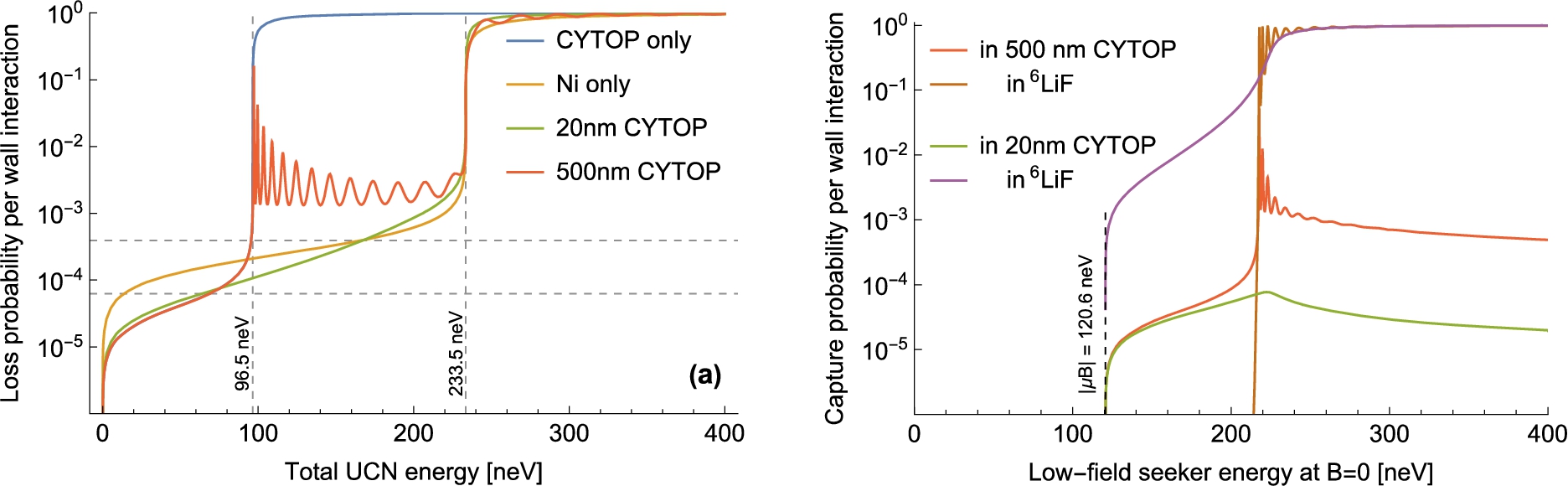
Calculated loss probabilities per wall interaction, for UCN confined by the commercial fluoropolymer CYTOPTM (trademark of AGC Chemicals) and natural nickel walls in a superfluid 4He filled vessel. All neutron energies are referenced to zero in the presence of helium: the neutron-optical potentials for CYTOP (
![Calculated loss probabilities per wall interaction, for UCN confined by the commercial fluoropolymer CYTOPTM (trademark of AGC Chemicals) and natural nickel walls in a superfluid 4He filled vessel. All neutron energies are referenced to zero in the presence of helium: the neutron-optical potentials for CYTOP (VCYTOP≈115 neV, fCYTOP≲2.7×10⁻⁵ [37]) and nickel (VNi≈252 neV, fNi≈12.5×10⁻⁵ [22]) are thus effectively reduced by V4He≈18.5 neV. The resulting cut-off energies for UCN trapping are illustrated by vertical gridlines. The upper (thick) curves show the loss probability at normal incidence, for reflection from an infinite half-space filled by the indicated material. Above the effective wall potential, neutrons are transmitted into the material and lost with probability approaching unity. The lower (thin) curves show the commonly-quoted angle-averaged loss probability μ¯(E), where μ¯(V)=πf when f is defined as in equation (10) [22]. This quantity is well-defined for UCN energies below each cutoff, and is systematically less than the normal-incidence loss probability for that material at the same kinetic energy.](https://content.iospress.com:443/media/jnr/2022/24-2/jnr-24-2-jnr220044/jnr-24-jnr220044-g002.jpg)
The effective potential barrier of a material wall can be enhanced for larger energies by means of multilayer structures that form artificial crystals in one dimension. High-reflecting stuctures can be obtained, for a narrow range of momenta perpendicular to the surface, by alternating layers of two or more materials with a high contrast of neutron-optical potential: i.e., by satisfying the Bragg condition for constructive interference of the reflected wave [33]. When the layer thickness is chirped as a function of depth in the mutilayer stack, the high-reflecting condition applies over a larger range of momenta and neutron “supermirrors” are obtained, as commonly exploited for guiding cold and thermal neutron beams [34,35]. The same principle applies for UCN, but for the materials used in supermirrors, the probability of loss per reflection remains at the percent level (or more) for perpendicular momenta exceeding the critical edge of the high-potential layers. This is due to neutron capture in the layers that must be traversed, in order for a neutron to reach the depth in the stack where its reflection condition is met. Therefore, supermirror technology can have an important role when UCN interact only a few times with each reflecting element (e.g., for guides and polarizers) – but its application in the context of UCN storage, where the number of surface interactions is much larger, remains limited.
We also note that in some situations it is desirable to eliminate the “supercritical”, or “marginally trapped”, component of a trapped UCN population – i.e., those neutrons whose kinetic energy exceeds the trapping potential, but which remain in the trap for significant time. This situation can lead to apparent loss rates with time constants shorter than the true storage time constant of the trap, which for instance motivates special “cleaning” procedures in order to avoid significant systematic errors in measurements of the neutron lifetime [38]. While the impact of supercritical UCN is less severe in most other measurements, certain velocity-dependent effects can nonetheless be exacerbated by their presence (e.g., reduced UCN polarization, or systematic errors related to the nondynamical phase shifts mentioned in Section 7), which also confounds the evaluation of a trap’s “true” storage time constant.
The geometry of a material trap also plays a role in determining its UCN storage time constant: more-frequent wall interactions in smaller containers typically lead to increased loss rates as compared to larger vessels of similar composition. To leading order, the loss rate due to wall interactions scales as the surface-area-to-volume ratio Λ of the confining vessel:
At the present time, the most successful 4He-based superthermal UCN sources have exploited wall coatings with only moderate optical potential, but very low loss. As demonstrated in the prototype source SUN-2 at the Institut Laue–Langevin, the combination of such a coating, especially as a thin layer over a lossier material with a higher value of V, is a productive compromise for achieving high in-situ densities. This can be qualitatively understood in terms of the UCN kinetic energy, which is reduced by the potential of the low-loss layer for those neutrons which transmit through it and reflect from the high-potential/high-loss layer underneath. Since the loss probability per wall interaction increases monotonically with kinetic energy (for fixed angle-of-incidence), this effective reduction in kinetic energy during the wall interaction leads to a correspondingly lower probability of loss. However, as illustrated in Fig. 3 the probability of neutron loss in this intermediate energy range can become significant, when the low-loss layer becomes thicker. This is essentially due to the same effect that limits the reflection efficiency of supermirrors: neutrons must traverse a significant quantity of material in order to reach the interface where reflection occurs (and then again, to exit the layer). Even for very weakly-absorbing materials, such losses rapidly accumulate with increased layer thickness.
Fig. 3.
Impact on UCN loss (absorption and transmission) at normal incidence, of low-potential/low-loss surface layers (CYTOP) and magnetic field gradients. The potential energy is set to zero in superfluid helium with no magnetic field applied. (a) Without magnetic fields. For very thin (
SUN-2 has demonstrated in-situ UCN densities of
Fomblin oil and grease belong to the class of materials with very low loss parameters, but also moderately low neutron-optical potential (
From the practical point of view, recent work has demonstrated that long storage times (especially at low temperature) can be achieved for a variety of coatings in small cells with few-liter volumes and surface-area-to-volume ratios on the order of
The ILL project SuperSUN [12] is attempting to approach the ultimate limit from beta-decay for in-situ storage (see also Refs. [25,26,59] and Section 6), by applying magnetic fields in an octupole configuration around the convertor vessel. This repels low-field seeking (LFS) UCN, which as a result reach the wall either with a much reduced velocity component perpendicular to it, or not at all [65]. As illustrated in Fig. 3 this effect significantly reduces the probability of loss; we also note that high-field seeking (HFS) UCN suffer correspondingly increased loss, and in SuperSUN this mechanism is exploited to produce polarized UCN directly in the source. In reality several percent of the convertor vessel’s total surface area cannot be completely shielded by magnetic fields, and for these surfaces it is especially critical to choose low-loss materials.
Fig. 4.
Estimated efficiencies at normal incidence for spin-selective in-situ detection, based on applied magnetic fields and thin reflecting layers (
![Estimated efficiencies at normal incidence for spin-selective in-situ detection, based on applied magnetic fields and thin reflecting layers (20 nm or 500 nm CYTOP) over an absorbing medium (6LiF). Solid curves indicate a 15 mT field strength at the reflector surface, i.e., what has already been demonstrated for metallic magnetic calorimeters [15]. For the dashed curves this field strength has been increased by an order of magnitude to illustrate the potential impact of future improvements (the same color schemes apply). Vertical gridlines at 96.5 neV indicate the wall potential of the reflecting layer, in superfluid helium. (a) Detection efficiency, and polarization contrast α, for a single interaction with the detector. (b) Detection efficiencies for a 200 s counting period in the “large” and “small” cells of Table 2, assuming an isotropic velocity distribution and detector area coverage of 10−3 inside the cell.](https://content.iospress.com:443/media/jnr/2022/24-2/jnr-24-2-jnr220044/jnr-24-jnr220044-g004.jpg)
4.In-situ UCN detection
The effect just described, by which magnetic field gradients at the wall surface increase [reduce] absorption losses for HFS [LFS] UCN, also provides a novel means of implementing spin-selective detection in-situ. A magnetic field gradient can be turned on at the end of an experimental cycle, such that HFS UCN then penetrate to an absorbing layer with increased probability. The resulting capture products could be detected and read out by a variety of methods, e.g., current-biased kinetic inductance detectors, cryogenic semiconductor detectors, or scintillation in the superfluid helium convertor induced by charged capture products that escape through the thin UCN-reflecting layer above the absorber. Since low-field seeking UCN can always be transformed into high-field seekers by nuclear magnetic resonance methods, this approach is suitable for selective detection of either spin component following a spin-precession experiment. This effect can also be demonstrated with cold neutrons at glancing incidence, and extrapolated to UCN by an appropriate scaling of the momentum components parallel and perpendicular to a planar sample surface. This is a significant advantage for scalable research and development: polarized neutron reflectometry (PNR) is a widespread method, with many public instruments available to users. Samples and experiments can be iteratively developed using PNR, with very favorable cost and efficiency as compared to UCN storage experiments.
In addition the layer thickness and magnetic field strength determine a finite range of perpendicular momenta in which the detection probability differs substantially between the two spin states. This is illustrated in Fig. 4 as a function of UCN energy, in a simplified picture where all wall interactions take place at normal incidence. Although the wall-interactions of stored UCN should be averaged over incidence angles, this simplified picture facilitates comparison with PNR measurements that are more suitable for research and development. Below this energy range, HFS neutrons do not penetrate easily to the absorber even in the presence of magnetic fields. Above it, both HFS and LFS neutrons reach the absorber even in the absence of magnetic fields. UCN exceeding the upper energy threshold will not be efficiently stored during an experimental cycle, and therefore do not contribute to the measurement; such marginally trapped neutrons may anyway be deliberately filtered out during filling or storage. The lower threshold for the detected spectrum can be adjusted via the magnetic field strength at the surface of the reflecting layer, e.g., by adjusting the current in a superconducting microstructure. This enables a limited degree of energy/momentum selectivity, which may be interesting for studies of systematic errors. For similar purposes one can envision several detector elements within a single cell, each with different thickness of the reflecting layer.
Fig. 5.
General concept of a multichamber in-situ UCN measurement. Left: Cryogenics apparatus based on the 3He refrigeration technology used for SuperSUN: (a) commercial cryocoolers, (b) vacuum vessel and thermal screens, (c) large-volume liquid-helium reserve at 4 K, (d) the needle valve for liquid-helium transfer to the 1-K pot, (e) 1-K pot with heat exchanger for pre-cooling of the 3He injection line, (f) superleak to extract superfluid 4He from the 1-K pot, (g) 3He/4He heat-exchanger to cool the superfluid, and superfluid delivery to the UCN convertor vessel, (h) pump to help achieve low temperature in the convertor vessel, (i) 4He pumps for the 1-K pot, (j) 3He pumps for cooling the heat exchanger, (k) polarized cold neutron beam incident on cells in the convertor vessel, (l) attenuated neutron beam exits the multicell stack. Elements such as magnetic shields or high-voltage that are needed specifically for the neutron EDM have been suppressed for clarity; we focus here on the possibility for statistical gains. Right top: UCN production within the measurement cells for a neutron EDM experiment. Right bottom: Three-dimensional artistic view of a multicell stack being illuminated by a beam, the remainder of which passes into a downstream monitor detector.
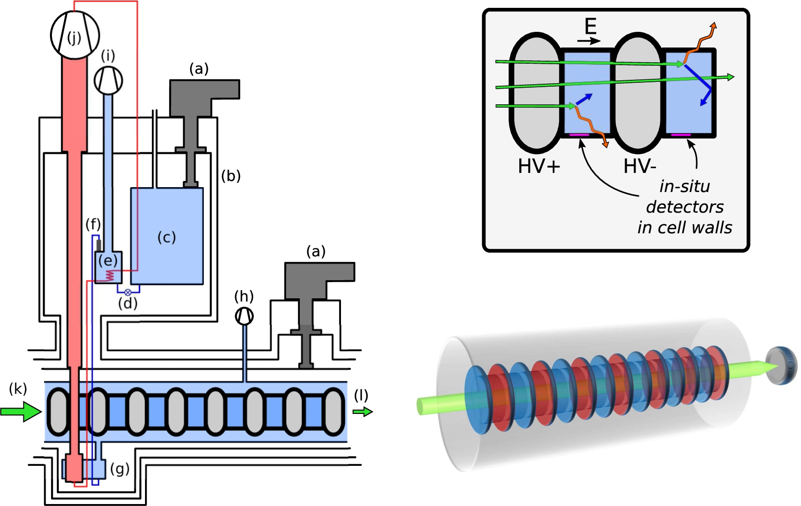
Figure 5 illustrates how such in-situ detectors could be implemented in the context of a multichamber neutron EDM measurement. There are clear challenges for introducing magnetic elements in experiments that rely extremely on the control and minimization of systematic errors related to magnetic fields. These can be substantially mitigated by the realization that the magnetic field for detection need only be applied after each experimental cycle is complete: the neutron polarization is then static, and the detector field can be oriented along the bias field of the experiment to eliminate diabatic transitions between spin states. Concerns related to induced magnetization of other components can be resolved by magnetic equilibration of the apparatus between experimental cycles, and by turning the detector field on and off adiabatically. Superconducting microstructures are a promising avenue for creating highly tailored field profiles. Further concerns connected with EDM experiments are discussed in Section 7, and estimates of the ultimate statistical reach for several scenarios are illustrated in Fig. 6.
Fig. 6.
Illustration of the potential statistical reach enabled by performing a neutron EDM experiment in-situ within a superfluid 4He UCN convertor. The horizontal gridline shows the 95% confidence limit set by the presently most-precise experiment [3], while the vertical gridline shows the mean free path of
![Illustration of the potential statistical reach enabled by performing a neutron EDM experiment in-situ within a superfluid 4He UCN convertor. The horizontal gridline shows the 95% confidence limit set by the presently most-precise experiment [3], while the vertical gridline shows the mean free path of 8.9 Å neutrons in superfluid 4He (≈16.6 m). It is assumed that measurement cells occupy 50% of the in-beam volume where UCN can be produced, i.e., that successive cells are spaced by a distance equal to their thickness. Each data series starts at left with a single cell pair, with each further point representing the cumulative addition of one more pair downstream. The corresponding parameters are given in Table 2. For each labelled pair the upper series (connected points) assumes that all UCN production is from unguided 8.9 Å neutrons, while the lower series (unconnected points) assumes perfect guiding of the entire neutron beam throughout the cell stack. These may be interpreted as limiting cases to illustrate the impact of beam-guiding on the final sensitivity; note that for the case of no guiding, extending the stack beyond a few meters does not greatly improve the sensitivity.](https://content.iospress.com:443/media/jnr/2022/24-2/jnr-24-2-jnr220044/jnr-24-jnr220044-g006.jpg)
Alternative approaches that could be applied for multichamber in-situ measurements include the use of 3He mentioned in Section 3.3, or extraction over a short distance within the superfluid to separate magnetic detector elements from the measurement volume. While in-situ UCN detection is not strictly required for in-situ experiments, it presents the conceptual advantage of completely eliminating transport and extraction losses. On the other hand, a detection method must be envisioned that does not spoil the long storage times required to achieve high UCN densities in the first place. As noted in Section 3.3, concepts involving neutron capture on 3He are likely to work as intended, but impose an undesirably low ceiling on τ.
We note in passing that this approach also offers a means of smoothly adjusting the in-situ loss rate for cryogenic UCN storage volumes. This may be useful for systematic studies in measurements of the neutron lifetime, or for accurately characterizing the storage properties of bottles with very low loss.
5.Challenges and limitations associated with in-situ experiments
Challenges common to many different types of in-situ experiments include the transport and/or guiding of cold neutrons through the convertor, in-situ detection of UCN, and balancing UCN accumulation time with measurement time. Cold neutron transport losses may in general be easier to minimize for ex-situ experiments, due to decoupling the requirements on the storage vessel that arise from the experiment, from those in the UCN convertor. The guiding requirements may also be affected by any transmissive elements such as confining barriers for UCN, which could increase the beam divergence through small-angle scattering. In addition to concerns of beam attenuation, the guiding requirements are very different for highly-divergent and well-collimated beams; the practical feasibility of real neutron guides also depends strongly on the needed surface area and quality.
There is also a penalty in duty factor for in-situ storage experiments, as compared to the case where UCN are extracted and stored in ex-situ volumes. In the latter case UCN production can continue during the measurement, since the source and measurement volumes are decoupled. While one is forced to compromise between saturated UCN density and duty factor if the source and experiment have very different storage time constants, in general a fresh ensemble of UCN can be ready to fill the experiment as soon as the previous holding period has concluded [12]. On the other hand, once a UCN ensemble is prepared for an in-situ measurement, UCN production should typically be stopped during the holding phase by blocking the cold neutron beam. Thus a duty factor of roughly
In fact, this problem is nontrivial to optimize: for a count-rate-limited frequency measurement repeated M times, the uncertainty now scales as
While we advocate the approach of using multiple experimental cells in parallel within an extended UCN convertor volume, practical challenges for development and commissioning remain. Any undesired effects that scale unfavorably with overall size (or number of modular units), in such an extended experiment will be difficult to address via modular prototype units. An example of this phenomenon is the probability for breakdowns in liquid helium under application of high voltage, relevant in EDM experiments, for which theoretical models propose a nonlinear dependence on the total surface area at high potential [30]. The experimentally observed frequency of such undesired breakdowns indicates that such models are not entirely general, but confirms a nonlinear scaling and further highlights important dependences on the electrode shape [40]. Since cells with zero electric field are needed to analyze EDM data, it may be possible to run usefully with high voltage disconnected from the “weakest” cells.
In addition, further requirements in particular experiments may conflict with certain aspects or possibilities that are advantageous for in-situ UCN production. Prominent examples of this for EDM measurements include the implementation of uniform magnetic fields (thus, magnetic trapping is not appropriate), high voltage (insulating materials severely limit the possibilities for cold neutron guiding), and volume comagnetometry (for which only 3He is an option in superfluid 4He convertors). Some of these aspects are further discussed in Section 7 below, but we do not attempt to survey them exhaustively. On the other hand for some experiments the requirements can reinforce each other, as in the case of magnetic trapping for measurements of the neutron lifetime (see the following section). In some cases it may be advantageous to use in-situ production and detection of UCN as a means of constraining systematic errors, i.e., as complementary to a measurement not based on UCN [54]. For yet other experiments such as the study of bound states of UCN in Earth’s gravity, some requirements are clear (e.g., the confining boundary should be isolated from mechanical vibrations) but further investigation may be required to fully evaluate their compatibility with an in-situ UCN source. Beyond that cited here and below, we are not aware of any work extensively considering in-situ UCN measurements; this highlights a need for both conceptual developments and feasibility studies.
6.Prior efforts towards in-situ experiments
Certain advantages of in-situ experiments with UCN have already been recognized, and have led to at least three separate experimental efforts based on this principle. A magnetic trap inside a 4He UCN convertor was used at NIST to measure
The CryoEDM experiment [9], which was installed at the Institut Laue–Langevin on the former H53 beamline, concluded without producing its intended measurement of the neutron EDM. The collaboration nonetheless supplied a great deal of fundamental information on UCN production in superfluid helium, and extensively developed apparatus for cryogenics and UCN handling. Challenges in the CryoEDM configuration included internal transport of UCN within the superfluid, from a production region exposed to the cold neutron beam into a separate measurement region of the cryostat. (Thus, in the sense we use here it was not a fully in-situ experiment.) Large cryogenic infrastructure also presented practical challenges in terms of the turnaround-times for iterative troubleshooting.
The major American project nEDM@SNS [5] is still in a preparatory phase, and seeks ultimately to measure the neutron EDM at the level of 4–
7.The neutron permanent electric dipole moment (EDM)
Motivated by the need for beyond-Standard-Model CP-violation to explain the observed cosmological baryon-antibaryon asymmetry, measurements of the neutron EDM play a key role in modern fundamental particle physics [13]. They are typically performed with spin-polarized UCN, by precision measurement of their spin-precession frequency, using Ramsey’s method of separated oscillatory fields in the presence of applied electric and magnetic fields. The scaling of statistical sensitivity with interaction time t is as described in Sections 1 and 5, which readily explains why neutron EDM measurements almost invariably use UCN. Two measurements are combined to determine the EDM, and for measurements with stored UCN this gives the statistical uncertainty
Figure 5 illustrates the modular components for a scalable multichamber EDM measurement at a schematic level. A polarized cold neutron beam enters the cryogenic cell stack, and produces polarized UCN directly in the measurement cells. Spin-precession in the presence of applied electric and magnetic fields is followed by in-situ detection, where polarization analysis is an intrinsic feature of the detector (see Section 4). Besides the prospects for greatly improved sensitivity (see Fig. 6) the main advantage of this approach is that its principal components and technologies can be thoroughly developed and tested in small-scale demonstration experiments. For example, the measurement cells can be prototyped at the single cell level and sequentially tested for: room-temperature UCN storage, dry cryogenic UCN storage, cryogenic UCN storage with liquid helium, UCN production with liquid helium, etc. The in-situ detectors can be developed via PNR, then extended to UCN, and later integrated in prototype cells for single-cell demonstrations of UCN production and in-situ detection. The large-scale project of integrating all components into a functioning system can also follow a staged approach: demonstration experiments with a smaller number of cells, lower UCN densities, and less performant detectors can be scaled up from modular units.
As illustrated in Fig. 6, divergence and guiding of the cold neutron beam significantly impacts the achievable precision for extended multicell stacks. Neutron supermirrors invariably consist of metallic layers, which makes them unsuitable for coating the insulating walls of a cell between the electrodes. If the cells are rotated to have the electric field direction perpendicular to the beam axis, then metallic coatings of the electrode surfaces could potentially be compatible with supermirror guiding of the beam in one dimension. A two-dimensional cell array could potentially further reduce loss in the unguided dimension.
EDM experiments must also perform extensive studies of systematic errors, to rule out the possibility of a false EDM signal (or cancellation!) generated by subtle effects arising from CP-conserving sources. The statistical sensitivity of a concrete experimental implementation is thus important not only for intrinsic sensitivity to a neutron EDM, but also for concluding – within a reasonable running time – the supplementry studies that are necessary to establish confidence in the result. It is to be expected that entirely new classes of systematic errors may become important as the statistical sensitivity of experiments improves, and that new techniques may be needed to constrain them.
To match the statistical reach of an in-situ measurement, systematic effects need to be under control at similar level:
Higher-order effects include spatially localized magnetic sources or high-order field gradients; these can arise respectively from imperfect demagnetization of inner components, or from the applied magnetic field. Such field profiles cause nondynamical phase shifts that are commonly referred to as “geometric phase” effects [19,39,50] although in the strictest sense this terminology applies only to the case where particle motion in the applied fields can be considered as adiabatic [10]. These effects can be mitigated to some extent by keeping the transverse dimensions of the measurement cells relatively small. The choice of small cell dimensions also helps to minimize the impact of magnetic field gradients more generally, but can limit the time constant for UCN storage due to the increased frequency of wall interactions. We further note that the alignment of magnetic field gradients (along the applied field direction) to Earth’s gravity is minimized for a stack of horizontally-oriented cells, which situation enables compensating linear field gradients with minimal error. These and other effects are mainly constrained by comagnetometry in present experiments, which unfortunately cannot be implemented in cryogenic cells without compromising statistics. Concepts such as solid-state optical or SQUID magnetometers embedded in cell walls could potentially offer an alternative approach to constrain the same effects, but require further investigation to assess feasibility in this context.
Demagnetization of glass cells for spin-precession measurements with noble gases has been demonstrated previously [27]; the application of this technique to larger and more massive UCN cells remains to be demonstrated. The suppression of ambient magnetic fields with high efficiency [6] and a stability at the ∼10 fT level has also been demonstrated, as well as the reduction of residual fields to a level of 0.1 nT [52,53]. The maximum allowable global gradient is on the order of 50 pT/m, assuming a magnetic field of 5 μT. This requirement is driven by geometric phase effects, which we already assume to be suppressed through use of
Applied fields with high homogeneity in low-magnetic-field environments have been demonstrated in present-generation neutron EDM measurements, but not in geometrical configurations appropriate for extended beamlines. One realistic layout for a possible magnetic shield is similar to the shield described in Ref. [55], i.e., constructed from an octagonal arrangement of pre-formed and clamped mu-metal sheets. We estimate that in order to achieve suitably small field gradients it would be necessary to include four additional shielding layers with 10 cm separation distance, and with an inner bore diameter large enough to ensure at least 30 cm distance to the low-field region. For such shielding geometries, transverse access holes can be implemented without excessive loss of shielding performance or creation of gradients in the innermost volume. This consideration is important for the implementation of shielded cryogenic volumes, which require large-diameter access routes for vacuum pumping and fluid transfer. Sensor readouts, electrical connections, and actuators normally require only smaller access holes. Shielding of frequencies above 1 Hz can be assisted by the vacuum chamber of the cryostat, which could be fabricated from aluminium. The applied magnetic field could be generated by a self-shielded double solenoid main coil, with correction coils and active field feedback, using sensor arrays placed in the isolation vacuum of the cryostat for field monitoring.
A further advantage of in-situ neutron EDM experiments is that the high dielectric strength of superfluid helium enables the application of higher electric fields, by up to a factor of 3.5 (and possibly more) with respect to the
Table 2
Parameter values for each of the calculations illustrated in Fig. 6. R is each individual cell’s radius, and L its thickness.
| Fig. 6 data series | R [cm] | L [cm] | ρ [cm-3] | τ [s] | α | ||||
| (a) | 5 | 7 | 18.5 | 55 | 1% | 7 | 250 | 0.85 | 23 |
| (b) | 5 | 7 | 3 | 4100 | 1% | 7 | 250 | 0.85 | 77 |
| (c) | 10 | 7 | 18.5 | 1600 | 50% | 8.5 | 350 | 0.85 | 23 |
| (d) | 10 | 7 | 3 | 50% | 8.5 | 350 | 0.85 | 77 |
8.Concluding remarks
It is notoriously difficult in UCN physics to deliver large gain factors for experimental quantities such as UCN density, and also in EDM experiments to control and constrain the numerous important sources of systematic error. While we do not claim that the large statistics gains outlined here can definitely be realized in combination with correspondingly low systematic errors for in-situ EDM experiments, we do maintain that their potential size and broad interest motivate extensive feasibility studies. We therefore propose a systematic program of research and development, based on modular and scalable cells that can be tested as prototypes in which UCN are both produced and stored. This approach would also support development and testing of further concepts such as in-situ UCN detection that are expected to be relevant for a variety of physics measurements, as well as those that are mainly relevant for specific experiments – such as magnetic shielding, the application of high electric fields, magnetometry, and comagnetometry in the case of EDM measurements. Future experiments based on this concept could proceed in a staged approach by gradually increasing the number of cells, thus substantially decoupling the challenges of scaling up a complete apparatus from those of establishing the essential performance and reliability of its base components.
Acknowledgements
We gratefully acknowledge funding from Heidelberg University’s Field of Focus 2, “Patterns and Structures in the Mathematics, Data, and the Material World” and from the Deutsche Forschungsgemeinschaft (DFG, German Research Foundation) under Germany’s Excellence Strategy – EXC-2094 – 390783311.
References
[1] | Y. Abe and N. Morishima, Ultracold and cold neutron cross-sections of liquid helium at low temperatures down to 0.1 K, Nuclear Instruments and Methods in Physics Research Section A: Accelerators, Spectrometers, Detectors and Associated Equipment 459: (1) ((2001) ), 256–264, https://www.sciencedirect.com/science/article/pii/S0168900200010093. doi:10.1016/S0168-9002(00)01009-3. |
[2] | Y. Abe and N. Morishima, Quantitative evaluation of ultracold neutron production and storage in superfluid helium, Nuclear Instruments and Methods in Physics Research Section A: Accelerators, Spectrometers, Detectors and Associated Equipment 463: (1) ((2001) ), 293–298, https://www.sciencedirect.com/science/article/pii/S0168900201002054. doi:10.1016/S0168-9002(01)00205-4. |
[3] | C. Abel, S. Afach, N.J. Ayres, C.A. Baker, G. Ban, G. Bison, K. Bodek, V. Bondar, M. Burghoff, E. Chanel, Z. Chowdhuri, P.-J. Chiu, B. Clement, C.B. Crawford, M. Daum, S. Emmenegger, L. Ferraris-Bouchez, M. Fertl, P. Flaux, B. Franke, A. Fratangelo, P. Geltenbort, K. Green, W.C. Griffith, M. van der Grinten, Z.D. Grujić, P.G. Harris, L. Hayen, W. Heil, R. Henneck, V. Hélaine, N. Hild, Z. Hodge, M. Horras, P. Iaydjiev, S.N. Ivanov, M. Kasprzak, Y. Kermaidic, K. Kirch, A. Knecht, P. Knowles, H.-C. Koch, P.A. Koss, S. Komposch, A. Kozela, A. Kraft, J. Krempel, M. Kuźniak, B. Lauss, T. Lefort, Y. Lemière, A. Leredde, P. Mohanmurthy, A. Mtchedlishvili, M. Musgrave, O. Naviliat-Cuncic, D. Pais, F.M. Piegsa, E. Pierre, G. Pignol, C. Plonka-Spehr, P.N. Prashanth, G. Quéméner, M. Rawlik, D. Rebreyend, I. Rienäcker, D. Ries, S. Roccia, G. Rogel, D. Rozpedzik, A. Schnabel, P. Schmidt-Wellenburg, N. Severijns, D. Shiers, R. Tavakoli Dinani, J.A. Thorne, R. Virot, J. Voigt, A. Weis, E. Wursten, G. Wyszynski, J. Zejma, J. Zenner and G. Zsigmond, Measurement of the permanent electric dipole moment of the neutron, Phys. Rev. Lett. 124: ((2020) ), 081803. doi:10.1103/PhysRevLett.124.081803. |
[4] | H. Abele, D. Dubbers, H. Häse, M. Klein, A. Knöpfler, M. Kreuz, T. Lauer, B. Märkisch, D. Mund, V. Nesvizhevsky et al., Characterization of a ballistic supermirror neutron guide, Nuclear Instruments and Methods in Physics Research Section A: Accelerators, Spectrometers, Detectors and Associated Equipment 562: (1) ((2006) ), 407–417. doi:10.1016/j.nima.2006.03.020. |
[5] | M.W. Ahmed, R. Alarcon, A. Aleksandrova, S. Baeßler, L. Barron-Palos, L.M. Bartoszek, D.H. Beck, M. Behzadipour, I. Berkutov, J. Bessuille, M. Blatnik, M. Broering, L.J. Broussard, M. Busch, R. Carr, V. Cianciolo, S.M. Clayton, M.D. Cooper, C. Crawford, S.A. Currie, C. Daurer, R. Dipert, K. Dow, D. Dutta, Y. Efremenko, C.B. Erickson, B.W. Filippone, N. Fomin, H. Gao, R. Golub, C.R. Gould, G. Greene, D.G. Haase, D. Hasell, A.I. Hawari, M.E. Hayden, A. Holley, R.J. Holt, P.R. Huffman, E. Ihloff, S.K. Imam, T.M. Ito, M. Karcz, J. Kelsey, D.P. Kendellen, Y.J. Kim, E. Korobkina, W. Korsch, S.K. Lamoreaux, E. Leggett, K.K.H. Leung, A. Lipman, C.Y. Liu, J. Long, S.W.T. MacDonald, M. Makela, A. Matlashov, J.D. Maxwell, M. Mendenhall, H.O. Meyer, R.G. Milner, P.E. Mueller, N. Nouri, C.M. O’Shaughnessy, C. Osthelder, J.C. Peng, S.I. Penttila, N.S. Phan, B. Plaster, J.C. Ramsey, T.M. Rao, R.P. Redwine, A. Reid, A. Saftah, G.M. Seidel, I. Silvera, S. Slutsky, E. Smith, W.M. Snow, W. Sondheim, S. Sosothikul, T.D.S. Stanislaus, X. Sun, C.M. Swank, Z. Tang, R.T. Dinani, E. Tsentalovich, C. Vidal, W. Wei, C.R. White, S.E. Williamson, L. Yang, W. Yao and A.R. Young, A new cryogenic apparatus to search for the neutron electric dipole moment, Journal of Instrumentation 14: (11) ((2019) ), P11017. doi:10.1088/1748-0221/14/11/P11017. |
[6] | I. Altarev, M. Bales, D. Beck, T. Chupp, K. Fierlinger, P. Fierlinger, F. Kuchler, T. Lins, M. Marino, B. Niessen et al., A large-scale magnetic shield with |
[7] | L. Babin, Caractérisation de HOPE un piège magnéto-gravitationnel à neutrons ultra-froids destiné à la mesure du temps de vie du neutron sur SUN2 une source superthermale de neutrons ultra-froids, PhD thesis, 2019. |
[8] | C.A. Baker, S.N. Balashov, J. Butterworth, P. Geltenbort, K. Green, P.G. Harris, M.G.D. van der Grinten, P.S. Iaydjiev, S.N. Ivanov, J.M. Pendlebury, D.B. Shiers, M.A.H. Tucker and H. Yoshiki, Experimental measurement of ultracold neutron production in superfluid 4He, Physics Letters A 308: (1) ((2003) ), 67–74, https://www.sciencedirect.com/science/article/pii/S0375960102017735. doi:10.1016/S0375-9601(02)01773-5. |
[9] | C.A. Baker, S.N. Balashov, V. Francis, K. Green, M.G.D. van der Grinten, P.S. Iaydjiev, S.N. Ivanov, A. Khazov, M.A.H. Tucker, D.L. Wark, A. Davidson, J.R. Grozier, M. Hardiman, P.G. Harris, J.R. Karamath, K. Katsika, J.M. Pendlebury, S.J.M. Peeters, D.B. Shiers, P.N. Smith, C.M. Townsley, I. Wardell, C. Clarke, S. Henry, H. Kraus, M. McCann, P. Geltenbort and H. Yoshiki, CryoEDM: A cryogenic experiment to measure the neutron electric dipole moment, Journal of Physics: Conference Series 251: ((2010) ), 012055. doi:10.1088/1742-6596/251/1/012055. |
[10] | M.V. Berry, Quantal phase factors accompanying adiabatic changes, Proc. Roy. Soc. Lond. A 392: ((1984) ), 45–57. doi:10.1098/rspa.1984.0023. |
[11] | G. Bison, M. Daum, K. Kirch, B. Lauss, D. Ries, P. Schmidt-Wellenburg, G. Zsigmond, T. Brenner, P. Geltenbort, T. Jenke, O. Zimmer, M. Beck, W. Heil, J. Kahlenberg, J. Karch, K. Ross, K. Eberhardt, C. Geppert, S. Karpuk, T. Reich, C. Siemensen, Y. Sobolev and N. Trautmann, Comparison of ultracold neutron sources for fundamental physics measurements, Phys. Rev. C 95: ((2017) ), 045503. doi:10.1103/PhysRevC.95.045503. |
[12] | E. Chanel, S. Baudoin, M.-H. Baurand, N. Belkhier, E. Bourgeat-Lami, S. Degenkolb, M. Jentschel, V. Joyet, M. Kreuz, E. Lelièvre-Berna et al., Concept and strategy of SuperSUN: A new ultracold neutron converter, Journal of Neutron Research 24: ((2022) ), these proceedings. doi:10.3233/JNR-220013. |
[13] | T.E. Chupp, P. Fierlinger, M.J. Ramsey-Musolf and J.T. Singh, Electric dipole moments of atoms, molecules, nuclei, and particles, Rev. Mod. Phys. 91: ((2019) ), 015001. doi:10.1103/RevModPhys.91.015001. |
[14] | S. Degenkolb, M. Kreuz and O. Zimmer, A tapered transition guide with irregular octagonal cross-section, Journal of Neutron Research 20: (4) ((2018) ), 117–122. doi:10.3233/JNR-180100. |
[15] | A. Fleischmann, L. Gastaldo, S. Kempf, A. Kirsch, A. Pabinger, C. Pies, J.-P. Porst, P. Ranitzsch, S. Schäfer, F.V. Seggern et al., Metallic magnetic calorimeters, in: AIP Conference Proceedings, Vol. 1185: , American Institute of Physics, (2009) , pp. 571–578. |
[16] | H. Godfrin, K. Beauvois, A. Sultan, E. Krotscheck, J. Dawidowski, B. Fåk and J. Ollivier, Dispersion relation of Landau elementary excitations and thermodynamic properties of superfluid 4He, Phys. Rev. B 103: ((2021) ), 104516. doi:10.1103/PhysRevB.103.104516. |
[17] | R. Golub, On the storage of neutrons in superfluid 4He, Physics Letters A 72: (4–5) ((1979) ), 387–390. doi:10.1016/0375-9601(79)90505-X. |
[18] | R. Golub, Ultracold neutrons: Their role in studies of condensed matter, Rev. Mod. Phys. 68: ((1996) ), 329–347. doi:10.1103/RevModPhys.68.329. |
[19] | R. Golub, C. Kaufman, G. Müller and A. Steyerl, Geometric phases in electric dipole searches with trapped spin-1/2 particles in general fields and measurement cells of arbitrary shape with smooth or rough walls, Phys. Rev. A 92: (6) ((2015) ), 062123. doi:10.1103/PhysRevA.92.062123. |
[20] | R. Golub and K. Lamoreaux, Neutron electric dipole moment, ultracold neutrons and polarized He-3, Phys. Rept. 237: ((1994) ), 1–62. doi:10.1016/0370-1573(94)90084-1. |
[21] | R. Golub and J.M. Pendlebury, The interaction of Ultra-Cold Neutrons (UCN) with liquid helium and a superthermal UCN source, Physics Letters A 62: (5) ((1977) ), 337–339, https://www.sciencedirect.com/science/article/pii/0375960177904340. doi:10.1016/0375-9601(77)90434-0. |
[22] | R. Golub, D. Richardson and S.K. Lamoreaux, Ultra-Cold Neutrons, Adam Hilger, (1991) . |
[23] | P. Heil, Bachelorarbeit zur Strahlvermessung SUN am H172 des Institut Laue Langevin, Bachelor’s thesis, Johannes Gutenberg-Universität, Mainz, (2013) . |
[24] | C. Herb, O. Zimmer, R. Georgii and P. Böni, Nested mirror optics for neutron extraction, transport, and focusing, Nucl. Instrum. Meth. A 1040: ((2022) ), 167154. doi:10.1016/j.nima.2022.167154. |
[25] | C.R. Huffer, Results and Systematic Studies of the UCN Lifetime Experiment at NIST, PhD thesis, North Carolina State University, 2017. |
[26] | P.R. Huffman, J.S. Butterworth, K.J. Coakley, M.S. Dewey, S.N. Dzhosyuk, R. Golub, G.L. Greene, K. Habicht, S.K. Lamoreaux, C.E.H. Mattoni, D.N. McKinsey, F.E. Wietfeldt, J.M. Doyle, Magnetic trapping of neutrons, Nature 403: ((2000) ), 62–64. doi:10.1038/47444. |
[27] | V. Hutanu, A. Rupp, J. Klenke, W. Heil and J. Schmiedeskamp, Magnetization of 3He spin filter cells, Journal of Physics D: Applied Physics 40: (15) ((2007) ), 4405–4412. doi:10.1088/0022-3727/40/15/003. |
[28] | V.K. Ignatovich, The Physics of Ultracold Neutrons, Oxford University Press, (1986) . |
[29] | T.M. Ito, E.R. Adamek, N.B. Callahan, J.H. Choi, S.M. Clayton, C. Cude-Woods, S. Currie, X. Ding, D.E. Fellers, P. Geltenbort, S.K. Lamoreaux, C.-Y. Liu, S. MacDonald, M. Makela, C.L. Morris, R.W. Pattie, J.C. Ramsey, D.J. Salvat, A. Saunders, E.I. Sharapov, S. Sjue, A.P. Sprow, Z. Tang, H.L. Weaver, W. Wei and A.R. Young, Performance of the upgraded ultracold neutron source at Los Alamos National Laboratory and its implication for a possible neutron electric dipole moment experiment, Phys. Rev. C 97: ((2018) ), 012501. doi:10.1103/PhysRevC.97.012501. |
[30] | A.L. Kupershtokh, E.I. Palchikov, D.I. Karpov, I. Vitellas, D.P. Agoris and V.P. Charalambakos, Stochastic model of breakdown initiation in dielectric liquids, Journal of Physics D: Applied Physics 35: (23) ((2002) ), 3106–3121. doi:10.1088/0022-3727/35/23/312. |
[31] | B. Lauss and B. Blau, UCN, the ultracold neutron source–neutrons for particle physics, SciPost Physics Proceedings 5: ((2021) ), 004. doi:10.21468/SciPostPhysProc.5.004. |
[32] | V.I. Lushchikov, Y.N. Pokotilovskii, A.V. Strelkov and F.L. Shapiro, Observation of ultracold neutrons, Sov. Phys. JETP Lett. 9: (1) ((1969) ), 23–26. |
[33] | S. Masalovich, Analysis and design of multilayer structures for neutron monochromators and supermirrors, Nucl. Instrum. Meth. A 722: ((2013) ), 71–81. doi:10.1016/j.nima.2013.04.051. |
[34] | F. Mezei, Novel polarized neutron devices: Supermirror and spin component amplifier, Communications on Physics (London) 1: (3) ((1976) ), 81–85. |
[35] | F. Mezei and P. Dagleish, Corrigendum and first experimental evidence on neutron supermirrors, Communications on Physics (London) 2: (2) ((1977) ), 41–43. |
[36] | T. Neulinger, Study of CYTOP and deuterated polyethylene coatings for ultracold neutron storage, PhD thesis, University of Illinois Urbana-Champaign, 2021. |
[37] | T. Neulinger, D. Beck, E. Connolly, S. Degenkolb, P. Fierlinger, H. Filter, J. Hingerl, P. Nordin, T. Saerbeck and O. Zimmer, Ultracold neutron storage in a bottle coated with the fluoropolymer CYTOP, Eur. Phys. J. A 58: (7) ((2022) ), 141. doi:10.1140/epja/s10050-022-00791-x. |
[38] | R. Pattie Jr., N. Callahan, C. Cude-Woods, E. Adamek, L.J. Broussard, S. Clayton, S. Currie, E. Dees, X. Ding, E. Engel et al., Measurement of the neutron lifetime using a magneto-gravitational trap and in situ detection, Science 360: (6389) ((2018) ), 627–632. doi:10.1126/science.aan8895. |
[39] | J.M. Pendlebury et al., Geometric-phase-induced false electric dipole moment signals for particles in traps, Phys. Rev. A 70: ((2004) ), 032102. doi:10.1103/PhysRevA.70.032102. |
[40] | N. Phan, W. Wei, B. Beaumont, N. Bouman, S. Clayton, S. Currie, T. Ito, J. Ramsey and G. Seidel, A study of DC electrical breakdown in liquid helium through analysis of the empirical breakdown field distributions, Journal of Applied Physics 129: (8) ((2021) ), 083301. doi:10.1063/5.0037888. |
[41] | F.M. Piegsa, M. Fertl, S.N. Ivanov, M. Kreuz, K.K.H. Leung, P. Schmidt-Wellenburg, T. Soldner and O. Zimmer, New source for ultracold neutrons at the Institut Laue–Langevin, Phys. Rev. C 90: ((2014) ), 015501. doi:10.1103/PhysRevC.90.015501. |
[42] | P. Schmidt-Wellenburg, K.H. Andersen and O. Zimmer, Ultra cold neutron production by multiphonon processes in superfluid helium under pressure, Nuclear Instruments and Methods in Physics Research Section A: Accelerators, Spectrometers, Detectors and Associated Equipment 611: (2) ((2009) ), 259–262, https://www.sciencedirect.com/science/article/pii/S0168900209015393. doi:10.1016/j.nima.2009.07.085. |
[43] | P. Schmidt-Wellenburg, J. Bossy, E. Farhi, M. Fertl, K.K.H. Leung, A. Rahli, T. Soldner and O. Zimmer, Experimental study of ultracold neutron production in pressurized superfluid helium, Phys. Rev. C 92: ((2015) ), 024004. doi:10.1103/PhysRevC.92.024004. |
[44] | A.P. Serebrov, E.A. Kolomensky, A.K. Fomin, I.A. Krasnoshchekova, A.V. Vassiljev, D.M. Prudnikov, I.V. Shoka, A.V. Chechkin, M.E. Chaikovskiy, V.E. Varlamov, S.N. Ivanov, A.N. Pirozhkov, P. Geltenbort, O. Zimmer, T. Jenke, M. Van der Grinten and M. Tucker, Neutron lifetime measurements with a large gravitational trap for ultracold neutrons, Phys. Rev. C 97: ((2018) ), 055503. doi:10.1103/PhysRevC.97.055503. |
[45] | F. Shapiro, Conf. On nuclear structure study with neutrons, Budapest (1972), in: Proc. Nuclear Structure Study with Neutrons, J. Erő and J. Szűcs, eds, Plenum Press, New York/London, (1975) , p. 259. |
[46] | T. Soldner, H. Abele, G. Konrad, B. Märkisch, F.M. Piegsa, U. Schmidt, C. Theroine and P.T. Sánchez, ANNI – a pulsed cold neutron beam facility for particle physics at the ESS, EPJ Web Conf. 219: ((2019) ), 10003. doi:10.1051/epjconf/201921910003. |
[47] | H.S. Sommers Jr., J.G. Dash and L. Goldstein, Transmission of slow neutrons by liquid helium, Physical Review 97: (4) ((1955) ), 855. doi:10.1103/PhysRev.97.855. |
[48] | A. Steyerl, Measurements of total cross sections for very slow neutrons with velocities from 100 m/sec to 5 m/sec, Physics Letters B 29: (1) ((1969) ), 33–35. doi:10.1016/0370-2693(69)90127-0. |
[49] | A. Steyerl, Ultracold Neutrons, World Scientific, (2020) . |
[50] | A. Steyerl, C. Kaufman, G. Müller, S.S. Malik, A.M. Desai and R. Golub, Calculation of geometric phases in electric dipole searches with trapped spin-1/2 particles based on direct solution of the Schrödinger equation, Phys. Rev. A 89: (5) ((2014) ), 052129. doi:10.1103/PhysRevA.89.052129. |
[51] | A. Steyerl, H. Nagel, F.-X. Schreiber, K.-A. Steinhauser, R. Gähler, W. Gläser, P. Ageron, J.M. Astruc, W. Drexel, G. Gervais and W. Mampe, A new source of cold and ultracold neutrons, Physics Letters A 116: (7) ((1986) ), 347–352, https://www.sciencedirect.com/science/article/pii/0375960186905876. doi:10.1016/0375-9601(86)90587-6. |
[52] | Z. Sun, P. Fierlinger, J. Han, L. Li, T. Liu, A. Schnabel, S. Stuiber and J. Voigt, Limits of low magnetic field environments in magnetic shields, IEEE Transactions on Industrial Electronics 68: (6) ((2020) ), 5385–5395. doi:10.1109/TIE.2020.2987267. |
[53] | Z. Sun, M. Reisner, P. Fierlinger, A. Schnabel, S. Stuiber and L. Li, Dynamic modeling of the behavior of permalloy for magnetic shielding, Journal of Applied Physics 119: (19) ((2016) ), 193902. doi:10.1063/1.4949516. |
[54] | W. Wei, A new neutron lifetime experiment with cold neutron beam decay in superfluid helium-4, J. Phys. G 47: (12) ((2020) ), 125101. doi:10.1088/1361-6471/abacdb. |
[55] | E. Wodey et al., A scalable high-performance magnetic shield for very long baseline atom interferometry, Rev. Sci. Instrum. 91: (3) ((2020) ), 035117. doi:10.1063/1.5141340. |
[56] | R.L. Workman et al., Review of Particle Physics, PTEP 2022: ((2022) ), 083C01. doi:10.1093/ptep/ptac097. |
[57] | D. Wurm, PanEDM at SuperSUN, PhD thesis, Technische Universität München, 2021. |
[58] | D. Wurm, D.H. Beck, T. Chupp, S. Degenkolb, K. Fierlinger, P. Fierlinger, H. Filter, S. Ivanov, C. Klau, M. Kreuz, E. Lelièvre-Berna, T. Lins, J. Meichelböck, T. Neulinger, R. Paddock, F. Röhrer, M. Rosner, A.P. Serebrov, J.T. Singh, R. Stoepler, S. Stuiber, M. Sturm, B. Taubenheim, X. Tonon, M. Tucker, M. van der Grinten and O. Zimmer, The PanEDM neutron electric dipole moment experiment at the ILL, EPJ Web Conf. 219: ((2019) ), 02006. doi:10.1051/epjconf/201921902006. |
[59] | A.R. Young, S. Clayton, B.W. Filippone, P. Geltenbort, T.M. Ito, C.-Y. Liu, M. Makela, C.L. Morris, B. Plaster, A. Saunders, S.J. Seestrom and R.B. Vogelaar, Beta decay measurements with ultracold neutrons: A review of recent measurements and the research program at, Los Alamos National Laboratory, Journal of Physics G: Nuclear and Particle Physics 41: (11) ((2014) ), 114007. doi:10.1088/0954-3899/41/11/114007. |
[60] | L. Zanini et al., Very Cold and Ultra Cold sources for ESS, 2022, Workshop on Very Cold and Ultra Cold Neutron Sources for ESS, https://indico.esss.lu.se/event/2810/contributions/15312/. |
[61] | Y.B. Zeldovich, Storage of cold neutrons, Sov. Phys. JETP 9: (6) ((1959) ), 1389. |
[62] | O. Zimmer, Imaging nested-mirror assemblies – a new generation of neutron delivery systems?, Journal of Neutron Research 20: (4) ((2018) ), 91–98. doi:10.3233/JNR-190101. |
[63] | O. Zimmer, Superfluid-helium UCN sources – “in-beam” versus “in-pile”, 2022, Workshop on Very Cold and Ultra Cold Neutron Sources for ESS, https://indico.esss.lu.se/event/2810/contributions/15317/. |
[64] | O. Zimmer, T. Bigault, S. Degenkolb, C. Herb, T. Neulinger, N. Rizzi, V. Santoro, A. Takibayev, R. Wagner and L. Zanini, In-beam superfluid-helium ultracold neutron source for the ESS, Journal of Neutron Research 24: ((2022) ), these proceedings. doi:10.3233/JNR-220045. |
[65] | O. Zimmer and R. Golub, Ultracold neutron accumulation in a superfluid-helium converter with magnetic multipole reflector, Phys. Rev. C 92: ((2015) ), 015501. doi:10.1103/PhysRevC.92.015501. |
[66] | O. Zimmer, P. Schmidt-Wellenburg, M. Fertl, H.-F. Wirth, M. Assmann, J. Klenke and B. van den Brandt, Ultracold neutrons extracted from a superfluid-helium converter coated with fluorinated grease, The European Physical Journal C 67: (3) ((2010) ), 589–599. doi:10.1140/epjc/s10052-010-1327-1. |


