
Very cold and ultra cold neutron sources for ESS
Abstract
The goal of the “Workshop on Very Cold and Ultra Cold Neutron Sources for ESS” was to discuss scientific cases, ideas and possibilities for the implementation of sources of Very Cold and Ultra Cold neutrons at the European Spallation Source. The ESS facility, presently under construction, offers several possibilities for in-pile UCN or VCN sources, in primis thanks to the available space below the spallation target where additional neutron sources can be placed to complement those above the target. Neutron beams can be extracted over a wide angular range with a grid of forty-two beamports with 6° average angular separation, allowing future instruments to be installed which may view either the upper or lower moderator systems. Of greatest interest for fundamental physics is the so-called Large Beamport foreseen for the NNBAR experiment. This beamport is also particularly well suited to feed a UCN source, for which several ideas were presented that employ either superfluid helium or solid deuterium as established neutron converter materials. Concepts for VCN sources make use of novel materials for VCN production and/or advanced reflectors to increase yields in the coldest part of the neutron spectrum from a cryogenic neutron source. In this paper we discuss these ideas and the possible locations of UCN and VCN sources at ESS.
1.The goals of the HighNESS project
The design of sources of slow neutrons for the European Spallation Source (ESS) has evolved over the years, and among other advances, led to the concept of low-dimensional moderators of high brightness [36]. While the initial configuration [43] placed neutron moderators above and below the spallation target (a 2.5-m diameter rotating wheel made of tungsten), the design optimization resulted in a single moderator system for the initial suite of instruments. For maximum versatility, this moderator system consists of a “bi-spectral” assembly of a water moderator at ambient temperature for thermal neutrons, and a liquid parahydrogen moderator for cold neutrons. Its peculiar shape (the so-called “butterfly”) resulted from the design goal to have thermal and cold neutrons available at all beamports of the facility. This “upper moderator” will be placed above the spallation target and will feed all fifteen instruments of the initial suite dedicated to neutron scattering [3]. Thanks to this optimization, the space below the target remains available for additional neutron sources. This, together with the fact that the initial instruments will occupy less than half of the forty-two beamports that will be available at ESS, offers important upgrade possibilities, which are explored within the HighNESS project [49,50].
HighNESS started in October 2020 as a three-year project, funded by the European Commission, with the goal of performing a design study of a second cold neutron source at ESS. This additional source will be placed below the spallation target, and will possess properties complementary to the upper moderator. The latter was optimised for high brightness, emitting neutrons from a small surface of only ≈6 cm width and 3 cm height. It will serve for applications that need a high flux density, notably the study of small samples of typically a few mm3 size, with moderate beam divergence. In contrast, the lower moderator will be optimised for high intensity (brightness integrated over emission surface), to facilitate applications where the total rate of neutrons emitted from the moderator surface is primordial, even at somewhat reduced brightness. The moderation or conversion of cold neutrons in secondary, colder neutron sources, discussed in later sections of this paper, is such a case where a large and intense primary cold source is crucial. Also, for the neutron instruments, a higher total emitted neutron beam intensity is sometimes preferable over a high neutron flux within only a small area. Some notable examples from particle physics that can profit from large and divergent neutron beams include a search for neutron-antineutron oscillations and measurements of the static electric dipole moment of the neutron [1,11,45]. Nested mirror optics [21,66] seem particularly efficient for delivery of such beams and will be discussed for an “in-beam” ultracold neutron source [8,17,44] in a separate contribution to these workshop proceedings [67].
A neutron spectrum colder than the one delivered by the bi-spectral upper moderator is a second design criterion for the lower source. Besides cold neutrons (CNs), a focus of HighNESS is on Very Cold Neutrons (VCNs, 10–120 Å wavelength range) and Ultra Cold Neutrons (UCNs,
The discussion of new ideas and possible configurations of intense sources for VCNs and UCNs was one of the main objectives of this workshop. While the first half of the HighNESS project was mostly dedicated to the design of the lower high-intensity CN moderator, these ideas shall be investigated in depth in the remainder of the project. This paper outlines conceptual designs for UCN and VCN sources discussed in the workshop, and their potential implementation using the ESS infrastructure. In the paper, geometries of the ESS source implemented in MCNP version 6.2 [61] are shown. MCNP was used to calculate the CN fluxes, which serve as input for further investigation of the VCN and UCN concepts presented.
2.The high-intensity cold moderator
In a high-power facility, the choice of the moderator material for a cold source is in practice limited to liquid hydrogen and liquid deuterium (LD2), which are well-established materials for cold moderators exposed to the strong radiation fields near the core of primary neutron production in high-flux research facilities, such as SNS, J-PARC, PSI, and ILL.
Liquid hydrogen is an excellent choice for pulsed sources. For parahydrogen, where the two hydrogen nuclei per molecule couple to zero total spin, (see Ref. [56] for the allowed combinations of nuclear spin, vibrational and rotational states for hydrogen and deuterium, and the corresponding ortho-para designations), a peculiar energy dependence of the neutron scattering cross section leads to a high transparency for CNs. As a result, most of the inelastic scattering events that cool the thermal neutrons entering the liquid parahydrogen occur within about 1–2 cm from the moderator surface. This property is at the basis of the concept of high-brightness low-dimensional moderators [36], which have been adopted for ESS. As discussed in [63], and references therein, it was found that, near the wide thermal premoderator above the ESS spallation target, a thin, flat parahydrogen moderator generates the highest CN brightness (see Fig. 1, left). With increasing moderator height, the brightness steadily decreases, whereas the total rate of CNs escaping from its emission surface increases. However, beyond a few centimeters, this total CN intensity saturates (Fig. 1, right). The choice of thickness made for the upper moderator (3 cm) was the result of a comprehensive analysis work that took into account the brightness and the brightness transfer to samples for the full ESS instrument suite [4].
Compared to liquid hydrogen, LD2 has a smaller scattering cross section for thermal neutrons and a lower absorption cross section. The slowdown of thermal neutrons is therefore possible in a larger volume, but the larger mean free path also leads to longer tails in the neutron pulses. LD2 thus offers a complementary option for CN production, where the main advantage is its capability to produce a larger total CN intensity. In fact, a preliminary study performed on the ESS geometry [27], showed that a large LD2 moderator can give an intensity about 3 times higher than liquid parahydrogen.
Fig. 1.
Illustration, how the thickness of a parahydrogen moderator located above a thermal neutron moderator impacts its CN brightness and intensity. Left: distribution of CN brightness (integrated time average for the neutrons with energy < 20 meV) at the moderator surface for a thin (1.5 cm) parahydrogen moderator (upper figure), and a 10 cm tall moderator (lower figure). Right: Comparison between CN brightness, total number of emitted neutrons, and heat load in a parahydrogen moderator, as a function of the moderator height. Figures adapted from Ref. [63].
![Illustration, how the thickness of a parahydrogen moderator located above a thermal neutron moderator impacts its CN brightness and intensity. Left: distribution of CN brightness (integrated time average for the neutrons with energy < 20 meV) at the moderator surface for a thin (1.5 cm) parahydrogen moderator (upper figure), and a 10 cm tall moderator (lower figure). Right: Comparison between CN brightness, total number of emitted neutrons, and heat load in a parahydrogen moderator, as a function of the moderator height. Figures adapted from Ref. [63].](https://content.iospress.com:443/media/jnr/2022/24-2/jnr-24-2-jnr220040/jnr-24-jnr220040-g001.jpg)
The high-intensity moderator based on LD2 has been designed in the first year of the HighNESS project. The model is shown in Fig. 2. There are two openings for neutron extraction, a large one (40 cm wide, 24 cm high) for the NNBAR experiment [1], designed to improve on an earlier search for neutron-antineutron oscillations [6], and a smaller one (
Of particular interest is also the performance of the lower moderator for 8.9 Å neutrons, which are needed for the CN conversion to UCN in superfluid 4He, also called He-II. The brightness of the lower moderator at the NNBAR opening at this wavelength, at 5 MW average power, is about
Fig. 2.
Horizontal cut view through the MCNP model of the high-intensity LD2 moderator. The moderator, placed below the spallation target, is 45 cm wide (perpendicular to the direction of neutron extraction), 47 cm long, and 24 cm high. There are two windows for neutron extraction, a large one (40 cm wide, 24 cm high) on the NNBAR side, with a cold Be filter to increase the flux above 4 Å (see discussion in Section 4.2.1); on the other side, there is a reentrant hole with dimensions of
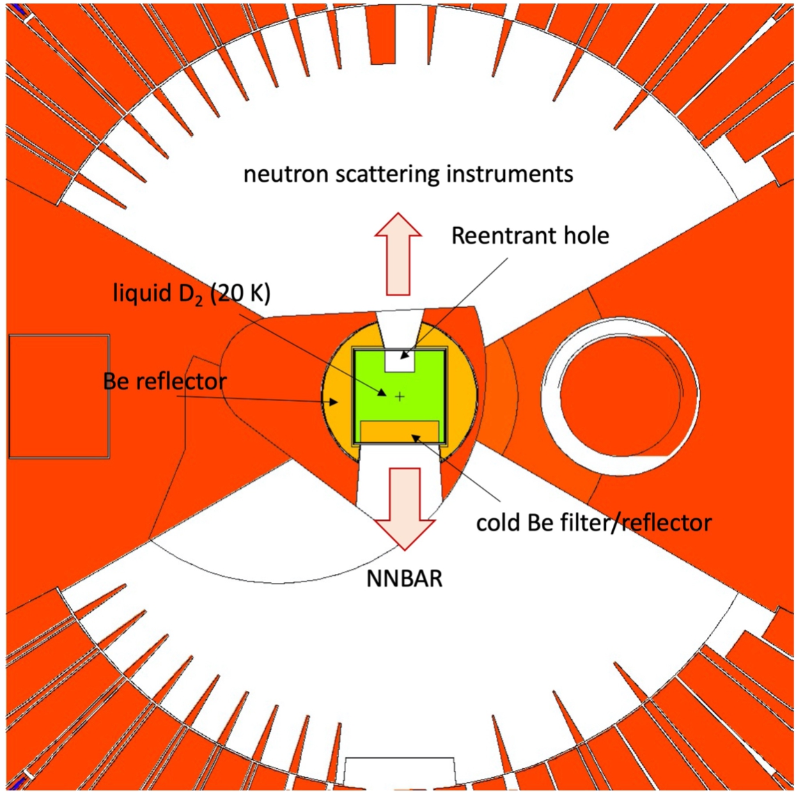
Table 1
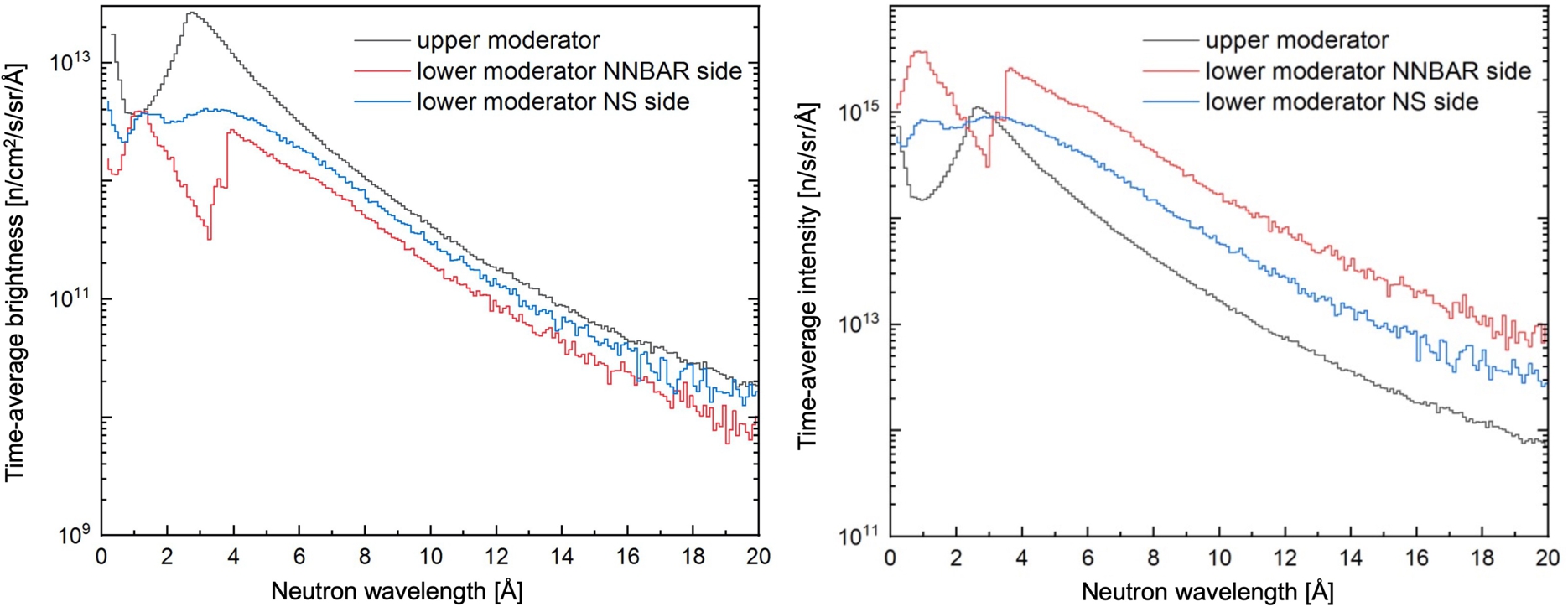
Calculated preliminary brightness and intensity at 5 MW average power, integrated over different wavelength ranges, for the lower moderator, for NNBAR and neutron scattering (NS) openings, compared with the upper moderator [63]. To calculate the intensity we considered the following size of emission windows for the lower moderator: NNBAR:
| BRIGHTNESS [n/cm2/s/sr] | |||
| NNBAR | |||
| NS | |||
| upper moderator | |||
| INTENSITY [n/s/sr] | |||
| NNBAR | |||
| NS | |||
| upper moderator | |||
Fig. 3.
Comparison of spectral brightness (left) and intensity (right) of upper and lower moderators, at 5 MW average power. The spectra for the upper moderator are the average over the 42 beamports. For the lower moderator, preliminary spectra are shown for two openings, i.e., for NNBAR and neutron scattering experiments. The calculated intensities refer to the emission windows with sizes specified in the caption of Table 1. Note the effect of the Be filter/reflector on the spectra for the NNBAR opening.
3.Basic concepts and possible locations of UCN sources
The most longstanding user facility for UCN physics, PF2 at the Institut Laue-Langevin, extracts the lowest-energy fraction of neutrons leaving a LD2 moderator [58]. More recently commissioned UCN sources and the majority of current source projects are based on “superthermal” UCN production [16], using either solid deuterium (SD2) or He-II as a material for CN conversion to UCNs in direct down-scattering events. The concepts under consideration for ESS are in line with these developments. In contrast to moderation, in a superthermal source, the neutrons stay out of thermal equilibrium with the colder medium, wherein Boltzmann suppression of UCN up-scattering enables buildup of a higher UCN density. To obtain the highest UCN production rates, the energy spectrum of the incident neutrons has to match the phonon spectrum of the medium. For SD2, existing LD2 CN sources are close to optimal, providing spectra that correspond to a neutron temperature,
Solid D2, prepared in the molecular rotational ground state and kept at temperatures below 10 K, is most effectively used “in-pile”, that is, near an intense primary neutron source, where it produces a high rate of UCNs (see Refs. [12,24,26,28–30,32,34,51,53,55] for operating, demonstrated and proposed SD2 sources). If the UCN source consists of only a small quantity of SD2, thus acting purely as a neutron converter, the incident neutrons need to be pre-moderated by an external CN source, typically of LD2. Alternatively, a large block of SD2 can serve simultaneously for both pre-moderation and final conversion to UCNs. This solution has been adopted at the Paul Scherrer Institute with its 30-L donut-shaped SD2 source in a dedicated target station at the SINQ neutron source [29]. Due to absorption and up-scattering, UCN storage lifetimes attainable in SD2 are at best on the order of several tens of milliseconds, requiring suppression of the (rotationally excited) para-deuterium content to a low percentage [31]. The short UCN survival time in SD2 requires a quick separation of the UCNs from the medium, which can be done using a direct extraction by a guide, or UCN storage in a large buffer volume containing a small converter, thus realizing the concept of a “thin-film” UCN source [14].
In contrast to deuterium, UCN storage lifetimes of several hundreds of seconds can be achieved in He-II, which is due to the unique property of 4He to not absorb neutrons at all. A necessary prerequisite is the technically feasible removal of the strongly absorbing isotope 3He from the superfluid [35,62,70], and a temperature of the converter below ≈0.6 K to suppress upscattering. Like SD2, He-II can be implemented in-pile, resulting in large UCN production rates [30,34,53]. However, the large heat load due to gamma radiation and neutrons near a strong primary neutron source prevents operation of the converter below 1 K, even if a very powerful cryogenic plant is available [53]. The UCN survival times in the warmer He-II are much shorter; however, being in a range of seconds to tens of seconds they are still typically two to three orders of magnitude larger than in SD2. The corresponding much longer mean free path, together with the outstanding UCN transparency of the perfectly homogeneous He-II [57], enables realization of UCN sources with large active volumes.
Complementary to in-pile locations, as first pointed out in Ref. [17], a He-II converter can also be placed in a CN beam far away from the primary source. Producing UCNs at a smaller rate due to the CN fluxes being lower than in-pile, the heat load at such remote positions can be kept low enough to operate the converter near 0.5 K. This enables the aforementioned long UCN storage lifetimes in the He-II, with an ultimate upper limit of ≈880 s due to neutron beta-decay. It is therefore possible to accumulate the UCNs in the converter, building up a large UCN density prior to extraction to an experiment [15]. A variant of this in-beam type of source employs a thermal beam feeding a He-II converter surrounded by a moderating cold reflector, which produces the required CN spectrum near the source [33].
Possible locations for UCN and VCN sources, identified so far in and around the ESS Target monolith, are shown in Fig. 4 and described in the subsections below. The monolith (shown in red) is a large shielding structure with an outer radius of 5.5 m, which contains the beamports as radial openings. A vertical cut view of a detailed MCNP model of the Target monolith is shown in Fig. 5. The target wheel and the upper and lower moderator assemblies are situated in its center (see Ref. [42] for more information on engineering aspects of the monolith). Any UCN and/or VCN source needs to fit in the existing ESS infrastructure and requires careful modeling and simulation of radiation fields with MCNP to assess UCN production rates but also heat loads and the necessary radiation shielding.
Fig. 4.
A horizontal cut through the target region, at the height of the LD2 moderator (shown in green) situated below the spallation target (not visible). The cylindrical region of radius 5.5 m around the center represents the shielding monolith (shown in red). The right figure is a zoom of the central part of the left figure. About half of its 42 standard beamports are visible in the cut plane. The possible locations of UCN sources, as studied within the HighNESS project are: (1) inside the “twister”; (2) inside the moderator cooling block; (3) in a standard beamport; (4) in the large beamport (shown as a white segment in the monolith); (5) outside the “bunker”, a heavy concrete shielding structure (shown in orange) placed around the monolith; the minimum distance of this location from the moderator is 15 m. See text for details and explanation of options for the various source positions.
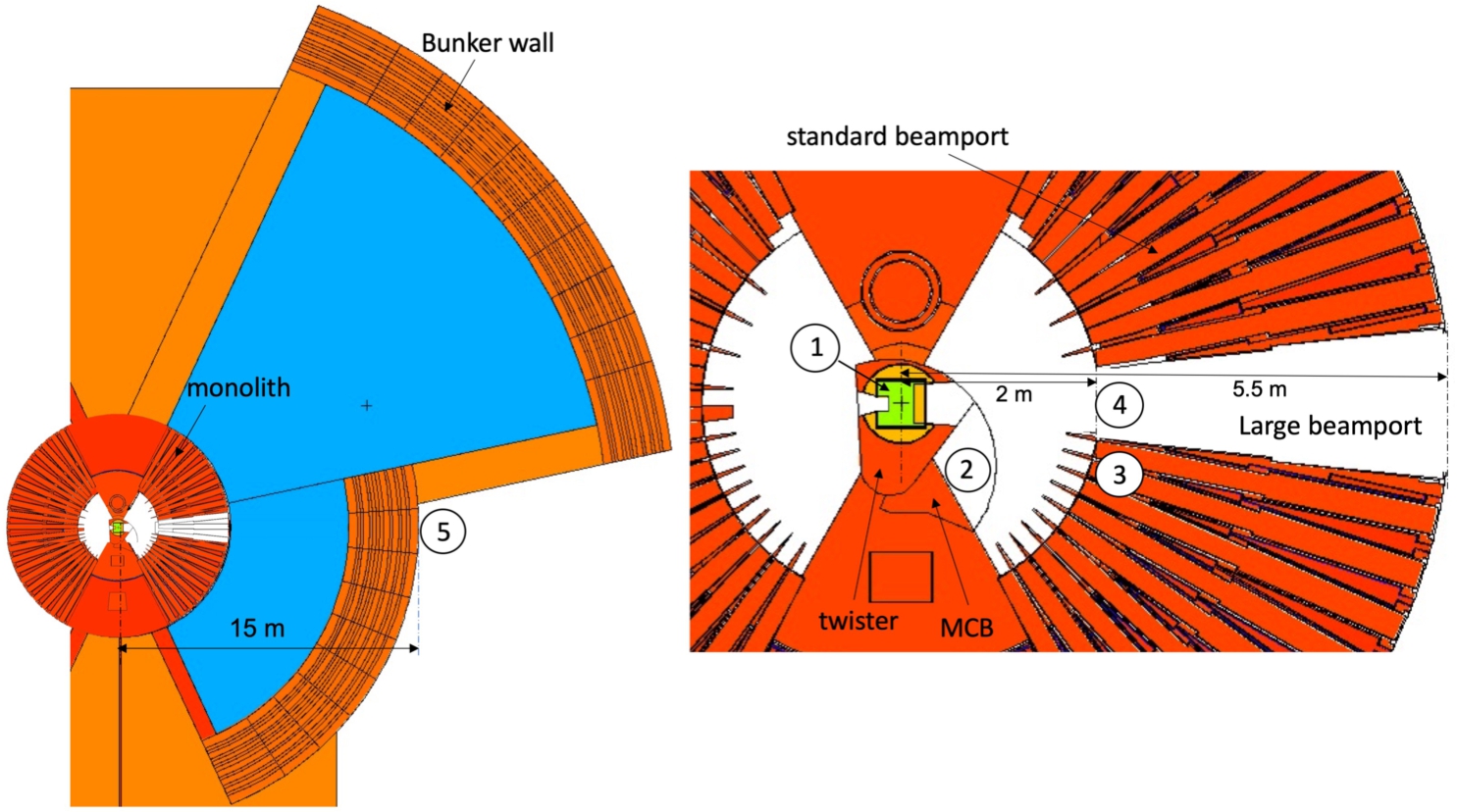
Fig. 5.
Vertical cut of the MCNP geometry of the Target monolith (11 m diameter). Openings in the shielding (in white) serve to extract neutrons from the upper and lower moderators. In this particular view the openings placed at 90° with respect to the proton beam are shown. Notice the shielding between the upper and lower moderator, obstructing the direct view onto the spallation target from the beamports.

The closer the UCN source is placed to the neutron production area, the larger is the UCN production rate, but the required cooling power also becomes larger. Locations beyond a minimal distance of 15 m are situated outside the “neutron bunker” [64]. This additional heavy-concrete shielding structure placed around the monolith contains beamline components such as choppers and shutters. It is accessible only while the spallation source is shut down, for example, for maintenance operations or installation of new instruments. In addition to this limitation, working in this area will be restricted due to activation of components. The more distant locations are therefore best suited if the UCN source requires frequent maintenance or changes of configuration, or if technically advanced equipment is involved, like a magnetic multipole UCN reflector around the converter [23,60]. Since the experiments fed by the source have to be placed outside the neutron bunker as well, provision of UCNs requires only a short UCN guide, which keeps UCN transport losses low. No transport losses at all occur in “in-situ” experiments [2,8,11,69], where the experimental setup is immersed in the bath of the He-II converter exposed to the CN beam.
3.1.Inside the twister (location 1)
The ESS upper and lower moderators are placed in a container called the twister, see Fig. 6. The expected lifetime of the twister plug is about 1 year when the facility operates at full power, corresponding to 5000 hours of operation per year at 5 MW. The lifetime is limited by radiation damage in the moderator vessel. To extract the plug for replacement, it must be rotated about the axis of its shaft, hence the name “twister”. For the first, and possibly second generation of the moderators, only the upper half of the twister contains a moderator and reflector, while the lower half is occupied by a steel structure acting as a shield and fast-neutron reflector. As discussed in Section 2, the high-intensity LD2 moderator to be implemented in the lower part of the twister will be of large volume. The perhaps only viable option for a UCN source integrated into the limited space left within the twister, seems to be a small-volume SD2 converter below or beside the moderator (location number 1 in Fig. 4). An alternative option would be to replace the LD2 moderator by a large block of SD2 (or another material) capable of producing high rates of both CNs and UCNs. However, this option would present the challenge of cooling a large volume of solid deuterium placed close to the spallation target, which might be not possible.
Fig. 6.
Left: a CAD drawing of the twister and moderator cooling block, with part of the inner shielding for display. Right: horizontal view at the height of the lower moderator (courtesy R. Holmberg). The LD2 moderator is placed inside the twister. A possible location of a secondary source inside the MCB is indicated by the dashed circle.
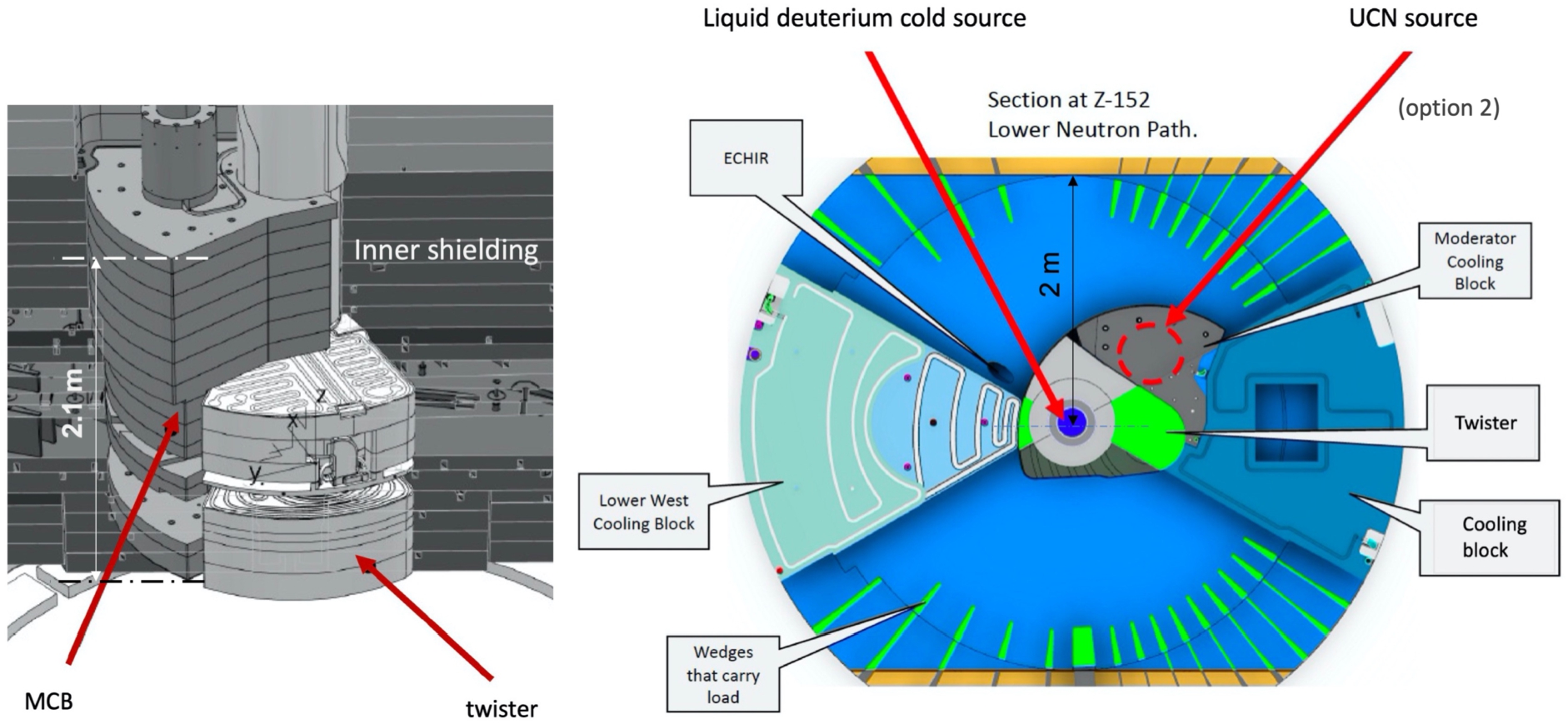
3.2.Inside the moderator cooling block (location 2)
As a second option within the monolith, we have identified a location inside the shielding block adjacent to the twister, called the Moderator Cooling Block (MCB) or Moderator Shielding Block (number 2 in Fig. 4, and Fig. 6). Despite the name, this block does not contain a moderator, its purpose being merely to provide shielding. The opportunity arises from the fact that the MCB is not a permanently installed component, as it needs to be extracted vertically during the operation of exchange of the twister and put back in place after a new twister plug is installed. While not currently foreseen, but verified with ESS engineers as being feasible, the MCB can be exchanged on this occasion by a modified version, accommodating an added converter for production of UCNs and/or VCNs. The previously installed MCB will then have to be transfered to a hot cell for a proper treatment and disposal of radioactive components. The MCB is actively cooled by water with pipes going through its shaft, and a modification of the cooling loop inserting a cryogenic system would be feasible. The location in the MCB offers the advantage of placing a source in a region of high flux, being close to the neutron-production region. The source could be a satellite source to the LD2 moderator placed inside the twister. This UCN source option is shown in Fig. 6 right.
Alternatively to implementing the UCN source together with the MCB as a pre-assembled unit, it could also be inserted horizontally through one of the beamports (which then cannot be used for other purposes). An advantage of this approach is that a change of configurations is possible independently of the exchange of the twister, and the source location can be adjusted in the radiation field to comply with the available cooling power. A disadvantage is that the source, together with its service pipes, have to fit through the beamport and need to be designed not to obstruct neighboring beamlines. As suggested in [48], to make optimal use of the available space, two adjacent beamports could be used, with one beamport housing the cooling channels of the source, and the other for source insertion and UCN extraction.
3.3.In a standard beamport in the monolith (location 3)
A third possibility is to implement a He-II based UCN source in a standard beamport in the monolith (number 3 in Fig. 4). The beamports start at 2 m from the moderator center, and when they are not used, they are plugged using elongated inserts which are 3.5 m long (Fig. 7, left). The channel limits the available space, but offers some flexibility in the choice of the distance of the source from the LD2 moderator. The difference with the second possibility, mentioned in Section 3.2, consists in filling the space of a beamport with the UCN converter, rather than using one beamport for the insertion of a converter (He-II or solid D2) in the MCB close to the target, and, if possible, a second beamport to extract neutrons. In this case, the beamport is filled with a He-II source. It is conceivable that the tip of this source can be placed at a distance from the LD2 moderator center closer than the 2-m distance at which the guides and beamport inserts begin (cf. Fig. 7, right). It is worth noting that, near the spallation target, a permanent radiation shield at the level of the target (cf. Fig. 5) reduces the height available for the source and its infrastructure, if the source is placed closer than 2 m from the moderator center. At larger distances, the full height of a standard beamport is available and would leave sufficient space to extract UCNs from the back end of the converter via a short section of vertical UCN guide followed by a bend and a horizontal guide towards an experiment. The viability of this technique has previously been demonstrated in He-II converter prototypes at TU Munich and at ILL [46,68,71], however, for much shorter distances of UCN transport than would be needed to deliver UCNs to an experiment out of the neutron bunker.
Fig. 7.
Left: a CAD drawing of a neutron beamport insert (NBPI), courtesy Bengt Jönsson. The dimensions of the tip of the insert are approximately
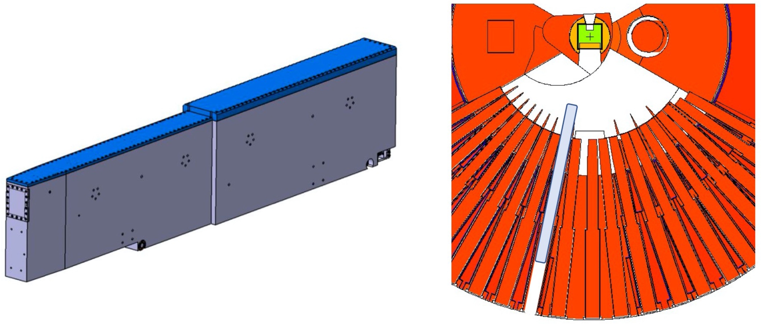
3.4.In the large beamport (location 4)
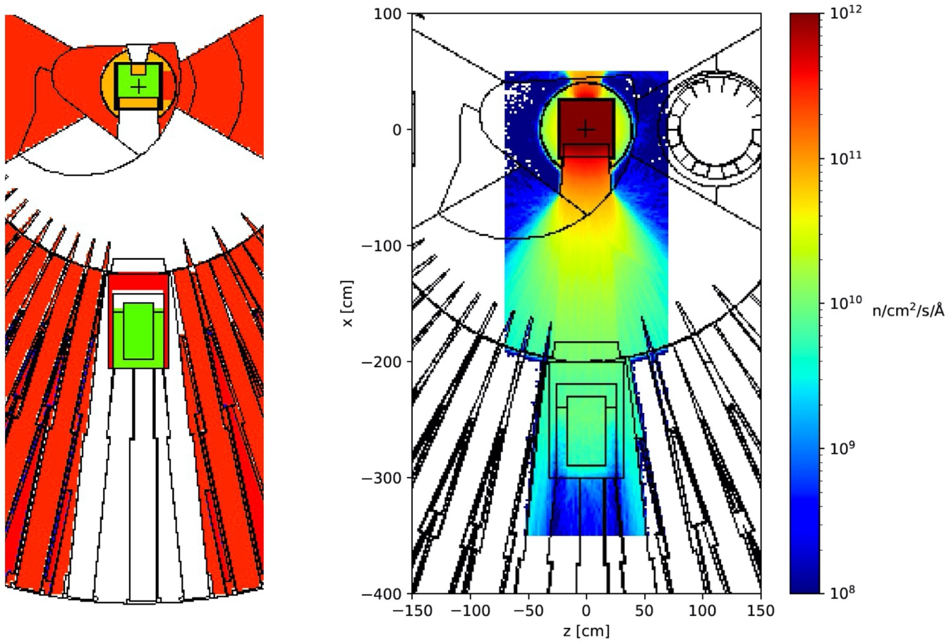
A fourth possibility (number 4 in Fig. 4) is to implement a UCN source in the Large Beamport (LBP), of which Fig. 8 shows two photos. This unique location provides free access for neutron extraction over a large angular range corresponding to three standard beamports. A steel frame holds three regular beamports for possible instruments. When both the frame and the three beamport inserts are removed, neutrons from the moderators can be extracted over a much larger solid angle than for a single beamport. The LBP is foreseen to first serve the NNBAR experiment, and could afterwards be exploited for the production of UCNs. A concrete proposal by Serebrov and Lyamkin foresees a vessel of 58 L filled with He-II, surrounded by a LD2 reflector and a lead shield [54]. Figure 9 shows results of preliminary MCNP simulations performed within HighNESS, providing a map of the unperturbed neutron flux at 8.9 Å, which induces the dominant one-phonon process of UCN production in He-II. The CN reflector is expected to increase this flux. The total heat load on the He-II converter at the indicated source location is about 8 W, which can be removed using existing cooling technology [54].
Fig. 8.
Left: View of the beamport tubes and the monolith vessel during installation (photograph taken in November 2021). The space above the beamport tubes is to be filled with permanent shielding blocks; the 2.7-m radius vessel will eventually host the target wheel, the twister and MCB and other components and shielding blocks. Right: front view of the large beamport frame during installation.
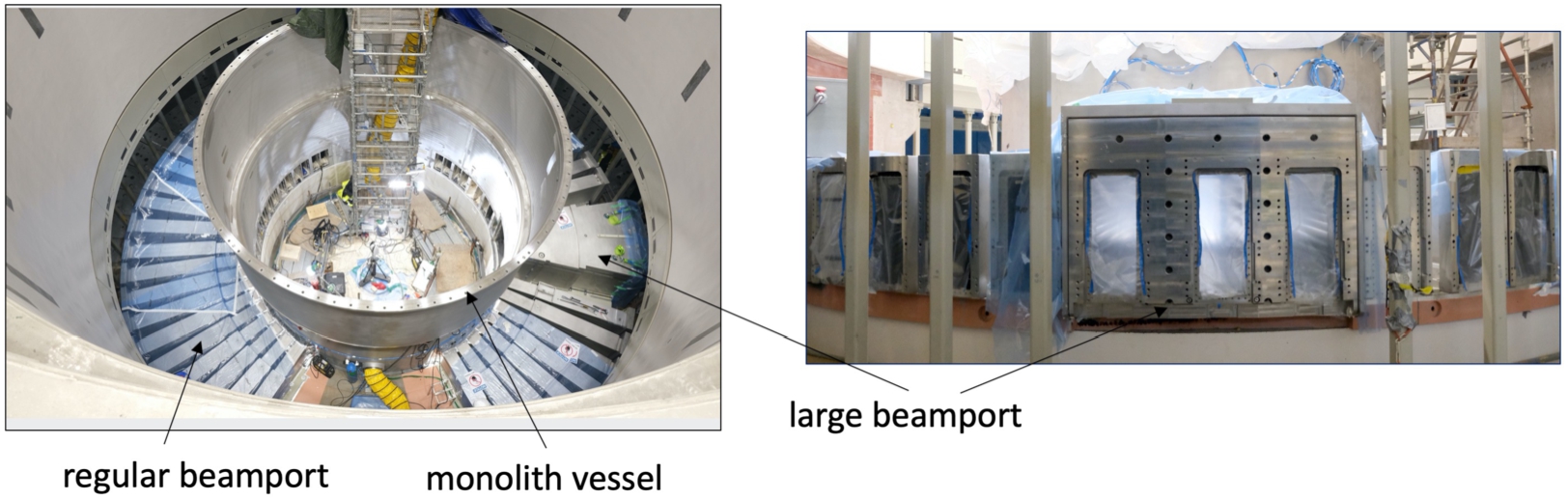
Fig. 9.
Left: MCNP geometry showing the He-II source backed by a LD2 reflector in the large beamport, concept of Serebrov and Lyamkin. Right: calculated flux map of 8.9 Å neutrons (unperturbed by the UCN source).
3.5.In-beam outside the monolith (location 5)
A final possibility places the UCN source in a cold neutron beam outside the monolith at distances
4.Basic concepts of VCN sources at ESS
Production of VCNs relies on the same neutron scattering processes as for UCNs, that is, either conversion of thermal or cold neutrons in single-step scattering events in a small-volume source, or by slowdown of neutrons by multiple scatterings in a sufficiently large moderator. The PF2 facility at ILL operates the only beamline presently available for VCN physics and thus sets a benchmark of performance. There, a strongly curved vertical neutron guide extracts the VCN beam from the long-wavelength tail of the spectrum of ILL’s large LD2 moderator (see Ref. [41] for spectra measured in various sections of the VCN beam. Note, however, that the facility is currently being upgraded, which is expected to change these spectra). It is one of the goals of the HighNESS project to explore both experimentally and theoretically possible improvements on VCN production and their extraction from a source.
In the original proposal of the HighNESS project, two approaches were considered for the design of such a source. One is based on a dedicated VCN source using a suitable material that would provide a high flux of VCNs, while another one, similarly to PF2, extracts VCNs directly from the cold source. At the workshop, an additional concept was suggested, that can be considered a merger of the two approaches. It is only discussed briefly here, as it is outlined in greater detail in Ref. [38].
4.1.Dedicated VCN source
Previous studies, using a set of candidate materials for which thermal scattering libraries were available, indicated that solid orthodeuterium and solid methane promise a higher VCN production performance than LD2 [13]. However, solid methane has the problem of radiolysis-induced radical formation followed by polymerization [22] and is therefore likely not suitable in a high-power spallation facility. Solid D2, on the other hand, is already well-established as an in-pile converter medium for UCN sources (see Section 3). Another class of candidate materials, whose suitability for moderation to the VCN energy range still needs to be demonstrated experimentally, are fully deuterated clathrate hydrates. In these inclusion compounds, guest molecules occupy cages formed by a rigid network of water molecules. Various local modes can be excited in incoherent inelastic scattering events, which provide a path for cascaded neutron cooling that is not kinematically restricted by a dispersion relation [65]. A strong candidate material investigated within HighNESS is the fully deuterated tetrahydrofuran (THF-d) clathrate hydrate (17D2O.C4D8O), which has a broad band of low-energy modes, as experimentally demonstrated for its undeuterated version [9]. The clathrate hydrate can be produced directly by freezing a stoichiometric THF-d/heavy-water mixture,11 allowing for simple preparation of a large-volume moderator. A necessary information to assess the suitability of a material for this purpose is the scattering function
For both materials, SD2 and THF-d clathrate hydrate, the highest VCN fluxes are to be expected at source locations near the spallation target. Although both materials are expected to deliver a higher VCN flux than the LD2 moderator, their use is justified only if they outperform the main source in the wavelength range of VCNs. This is very difficult to achieve, as shown in Ref. [13], and requires the highest possible incident flux, so that the best location for a VCN source would be below the spallation target, thus replacing the cold source. This solution would have to cope with the challenge of cooling the material to the needed temperature. Monte Carlo simulations for a source placed at various distances from the spallation target will be carried out, to determine not only the neutronic performance, but also the heat load on the moderator and hence the cooling requirements. While for SD2 a temperature of 5 K seems optimal [12], the THF-d clathrate hydrate would best be operated below 2 K. At such low temperatures, the local modes are predominantly populated in the ground state, which suppresses up-scattering. From a practical point of view, He-II can be used for effective cooling of the weakly thermal-conducting clathrate hydrate. As mentioned above, the material can be recrystallized in the clathrate structure by simply freezing the mixture of its constituents. Annealing in situ is therefore possible and could become an asset if the radiation hardness of the material is found to be an issue. It thus follows as a further criterion for the location of the source that the degradation of its performance has to be sufficiently slow, such that the time needed for annealing does not significantly deteriorate the duty cycle.
4.2.Use of advanced reflectors to increase the VCN flux
4.2.1.The role of conventional reflectors
In general, the output of slow neutrons from a CN or VCN source (moderator or converter) can be increased by a neutron reflector that covers a large solid angle around the source and reduces neutron losses from the source region. Ideally, both the primary neutron source and the secondary cold source would be contained in a reflector with a high albedo for all neutron energies, thus enhancing the flux in a quasi-trapped neutron field. The albedo is an important geometry-dependent parameter which characterizes the probability of a neutron escaping from the moderator to diffuse back into the moderator [7].
At ESS the CN moderators are mounted near the spallation target, each separated from this primary source by a thermal premoderator. The latter is made of a layer of water with thickness of 3 cm for the upper moderator, and 2.5 cm for the lower moderator. As water is a hydrogen-rich material, it is most effective for thermalization of the incident fast neutrons but also possesses a short diffusion length due to its strong incoherent scattering (and, compared to deuterium, much larger absorption). This layer therefore also plays the role of a reflector for neutrons from the CN moderator. The remaining side walls of the lower cold moderator are also covered by layers of water, however of smaller thickness (1 cm). It was found in the design of the LD2 moderator, that these lateral layers increase the CN output by about 20 %. They serve purely as reflectors of cold and thermal neutrons that escape the cold moderator.
An important role in the increase of the performance of the LD2 moderator is played by beryllium, which surrounds both the upper and lower moderators. The Be reflectors (at room temperature) are of cylindrical shape and occupy most of the space inside the twister envelope that is not taken by the moderators or by cooling pipes. Due to the much smaller size of the upper moderator, the effect of the Be reflector on the cold brightness, estimated to be about a factor 3, is much larger than for the lower moderator, for which the gain is reduced because of its large size, and the correspondingly reduced amount of beryllium. Still, the gain is of the order of 20 %, which justifies its use.
For thermal-neutron wavelengths below the Bragg cutoff at 3.94 Å, the neutron cross section of Be is dominated by coherent scattering off its crystallites. The material has a weak absorption and an almost vanishing incoherent scattering cross section. The inelastic scattering that remains beyond the Bragg cutoff can be suppressed by lowering the temperature, resulting in high transparency for long-wavelength neutrons. This feature is typically employed in Bragg filters to clean the spectrum of a neutron beam from unwanted short wavelengths. While for this reason a Be reflector works better at ambient temperature, a block of polycrystalline Be cooled below 80 K, implemented directly on the CN moderator in direction of the LBP is an asset. Such a block transmits the wanted long-wavelength neutrons but retro-diffuses a large fraction of the neutrons below the Bragg cutoff, which enhance the neutron flux in the moderator and thereby also the intensity of the extracted cold beam. This results in a CN flux increase in the direction of the LBP in the range of 20 %.
4.2.2.Use of advanced reflectors
To increase the VCN flux from a conventional cold source, we consider the use of different advanced reflector materials, of which the HighNESS project includes four classes, namely 1) nanodiamonds, 2) magnesium hydride, MgH2, 3) graphite intercalated compounds, and 4) deuterated clathrate hydrates.
- Diamond Nanoparticles (NDs) have been studied extensively in the last 15 years and exhibit a large albedo for VCNs [10,39,40]. They have large coherent scattering, which in the CN range gives “quasi-specular” reflections at small angles, while in the VCN range the scattering becomes almost isotropic. These properties suggest two possible applications of ND layers: i) around a VCN source to improve its performance, and ii) in the extraction channel of a cold source. The first application employs the reflector much in the same way as any other reflector around a moderator (see Section 4.2.1), with the only difference that NDs extend the capabilities of conventional materials, offering a particularly efficient option for VCNs. This makes it possible to set up a flux trap to reduce leakage of VCNs produced within the source, thus increasing its output to beamports. It is also conceivable to employ ND layers to form a cavity connecting a primary cold source with a secondary, colder VCN source placed in an environment of reduced heat load. The cavity enhances the probability of neutrons emitted from the cold source to arrive at the VCN source. This scenario could be realized with a secondary source placed in the MCB.
The second application can be seen as a solution similar to placing neutron optical mirrors at the moderator exit, which might be not possible in the strong radiation fields of ESS. We recall that the neutron guides viewing the upper moderator at ESS start at 2 m from the moderator center, a choice dictated by the large number of beamports, and their average angular spacing of 6°. However, as only few instruments shall exploit the lower moderator, and therefore their mutual constraints are much reduced, there is more freedom in the beam extraction design from the lower moderator. It could then be possible to get a significant increase in VCN flux by placing a channel coated with NDs, several tens of cm long, right at the moderator exit, followed by neutron optics to further transport neutrons, e.g. to a sample. While diluting the source brightness into a larger volume element of beam phase space, such a channel can increase the total neutron flux with respect to an uncoated extraction tube. A recent paper has indicated possible gains close to a factor of two in the flux of neutrons with divergence less than 2°, and an order-of-magnitude gain for neutrons with divergence more than 2° [25]. These gains extend over the CN and VCN range. Still, one needs to verify the effect for VCNs above about 30 Å, since for longer-wavelength neutrons the range of quasi-specular scattering angles increases. Also, the applicability of high-divergence neutrons at the end of the extraction channel is an open question. For various reasons, nested mirror optics (NMO) might be a more efficient solution. Firstly, such devices can prevent neutron losses due to under-illumination of a remotely placed guide (see discussion in Section 6.1 of Ref. [21]). Secondly, depending on the implementation and in contrast to long guides, NMO transport neutrons with only one or two reflections from a source to a target, which mitigates losses due to the imperfect mirror reflectivity. Due to the well-defined neutron reflection angles occurring in NMO, the spectrum of the extracted neutrons can be tailored by choice of the reflectivity profiles of the supermirrors that constitute the device, which includes a spectral cutoff at a short wavelength, and even the possibility of monochromatization by using bandpass supermirrors [66]. It is to be noted, however, that most of the ESS beamports do not provide sufficient access to the moderators for a direct extraction of a divergent VCN beam by NMO, so that a short in-pile neutron transport system (ND or mirror channel) would still be required. In this respect, the LBP offers the best conditions available at the ESS.
- Magnesium hydride (MgH2) is another promising material which has been proposed for diffuse reflection of CNs [18], providing an albedo of about 0.4–0.5 over the whole CN spectrum and a weak neutron up-scattering. This material therefore might increase the performance of a cold source and could, possibly in combination with another reflector such as the above-mentioned NDs, lead to an improved VCN output as well. Several design configurations are possible and will be tested.
- Graphite intercalated compounds (GICs). Directions for further investigation of CN reflectors include materials with larger-wavelength Bragg cutoff than Be, notably intercalated graphite compounds (>10 Å) which are also addressed in experimental work within HighNESS. Such materials would be capable of reflecting the majority of the CN spectrum from the LD2 source, so that the inelastic scattering off ambient Be might no longer be needed to prevent neutron leakage from the moderator. Cooling the reflector, which would increase the volume of the low-temperature neutron field [37], might then lead to an additional gain in CN flux.
- Deuterated clathrate hydrates have not only potential as VCN moderators but also as reflectors to cover the CN range from standard LD2 cold sources. Their large albedo for CN is due to their atypically weak neutron absorption and unusually large crystallographic unit cells, leading to Bragg scattering below large cut-off wavelengths of 20 Å and 24 Å for the most common hydrate structures CS-II and CS-I, respectively. Used as a reflector, the clathrates thus seem able to enhance the output of a standard LD2 moderator, notably when cooled to low temperature to avoid re-thermalization, while NDs are interesting for reflection of VCNs with
For reliable Monte Carlo particle transport calculations, thermal scattering libraries for these novel materials are needed. At the time of writing, such libraries were available for a particular type of NDs, generated from experimental results given in Ref. [59], and for MgH2 [18,47]. Additionally, a new library for SD2 at 5 K has been developed [19]. Libraries for further types of NDs, GICs and clathrate hydrates are under development and will be tested as soon as they become available. Several design options for advanced neutron reflector geometries are to be investigated within the HighNESS project as well. An experiment for testing advanced reflector concepts in prototype geometries is currently under design and is planned to be performed in 2023 at the moderator test station under construction at the Budapest Research Reactor.
4.3.Combined use of dedicated VCN moderator and advanced reflectors
Finally, the two different approaches described above for a VCN source can be combined in a more complex but potentially advantageous design. In view of the challenging cooling of a large amount of SD2 close to the spallation target, one could consider a smaller “slice” of SD2 placed next to the main LD2 moderator. Additionally, a judicious design of the geometry of ND reflectors, inserted in a hybrid liquid-solid D2 moderator, could enhance the VCN generation at the source and its transport towards the instruments. This concept proposed by Nesvizhevsky [38], will also be explored in the second half of the HighNESS project.
5.Conclusions
This article has outlined several options for implementation of UCN and VCN sources at ESS. Conceptual and engineering design of UCN sources can build on a broad experience gathered by various research groups around the globe during several decades. The main lines of recent developments, utilizing neutron conversion in SD2 and He-II, were presented at the workshop. This paper highlighted ideas and concepts for UCN sources discussed for ESS, and gave an overview of the various possible locations. More detailed descriptions can be found in other contributions to the workshop proceedings.
For VCN sources, the state of the art is rather different. At present, the only beamline for VCN exists at the instrument PF2 at ILL, which is fed from a strongly curved vertical neutron guide viewing a LD2 moderator. Given the potential scientific impact for several fundamental-physics projects, it has been considered as timely to include in the HighNESS project an exploration of possibilities for creation of a dedicated VCN source of high intensity at the ESS. The multifaceted works towards this goal start from basic experimental research, to determine macroscopic scattering cross sections and to study the suitability of advanced materials for neutron reflection and moderation of CNs to the VCN energy range. Materials investigated include nanodiamonds, magnesium hydride and intercalated graphite for neutron reflection, and deuterated clathrate hydrates for neutron moderation at temperatures below 2 K. The experimental data serve to benchmark physical models and also as direct input for Monte Carlo simulations of promising configurations of moderator/reflector assemblies. The project also includes an analysis of the extraction of neutrons in the long-wavelength tail of the spectrum from a LD2 moderator, using an ND reflector.
All source options discussed in these proceedings will be investigated in depth in the remainder of the HighNESS project. It is the hope of the authors that the community will continue to provide essential input for the design of intense UCN and VCN sources, thus preparing the field for future world-leading experiments at ESS.
Notes
1 This was demonstrated in recent experiments using ILL’s diffractometer D20 (experiment numbers 1–10–42 and 1–10–49); results to be published.
Acknowledgements
We acknowledge the very precious inputs from Anatolii Serebrov and his team on the identification and validation of the most promising locations of the in-beam UCN sources, and for providing first concepts for the configuration of such sources. We would like to thank our colleagues Ulf Odén and Carwyn Jones from the ESS Target division for analyzing the idea and confirming the possibility of using the moderator cooling block to place a secondary source.
This work was funded by the HighNESS project at the European Spallation Source. HighNESS is funded by the European Framework for Research and Innovation Horizon 2020, under grant agreement 951782.
References
[1] | A. Addazi et al., New high-sensitivity searches for neutrons converting into antineutrons and/or sterile neutrons at the HIBEAM/NNBAR experiment at the European Spallation Source, J. Phys. G: Nucl. Part. Phys. 48: ((2021) ), 070501. doi:10.1088/1361-6471/abf429. |
[2] | M. Ahmed, R. Alarcon, A. Aleksandrova, S. Baeßler, L. Barron-Palos, L. Bartoszek, D. Beck, M. Behzadipour, I. Berkutov and J. Bessuille, A new cryogenic apparatus to search for the neutron electric dipole moment, Journal of Instrumentation 14: (11) ((2019) ), 11017. doi:10.1088/1748-0221/14/11/P11017. |
[3] | K.H. Andersen et al., The instrument suite of the European Spallation Source, Nuclear Instruments and Methods in Physics Research Section A: Accelerators, Spectrometers, Detectors and Associated Equipment, 957: ((2020) ), 163402. |
[4] | K.H. Andersen, M. Bertelsen, L. Zanini, E.B. Klinkby, T. Schönfeldt, P.M. Bentley and J. Saroun, Optimization of moderators and beam extraction at the ESS, Journal of Applied Crystallography 51: (2) ((2018) ), 264. doi:10.1107/S1600576718002406. |
[5] | C.A. Baker, S.N. Balashov, J. Butterworth et al., Experimental measurement of ultracold neutron production in superfluid 4He, Phys. Lett. A 308: ((2003) ), 67. doi:10.1016/S0375-9601(02)01773-5. |
[6] | M. Baldo-Ceolin et al., A new experimental limit on neutron–antineutron oscillations, Phys. C 63: ((1994) ), 409. doi:10.1007/BF01580321. |
[7] | K.H. Beckurtz and K. Wirtz, Neutron Physics, Springer, Berlin Heidelberg, (1964) . |
[8] | E. Chanel et al., Concept and strategy of SuperSUN: A new ultracold neutron converter, these proceedings. |
[9] | H. Conrad, W. Kuhs, K. Nuenighoff, C. Pohl, M. Prager and W. Schweika, Inelastic scattering and spectral measurements of advanced cold moderator media, Physica B 350: ((2004) ), 647. doi:10.1016/j.physb.2004.03.173. |
[10] | R. Cubitt, E. Lychagin, A.Y. Muzychka, G. Nekhaev, V. Nesvizhevsky, G. Pignol, K. Protasov and A. Strelkov, Quasi-specular reflection of cold neutrons from nano-dispersed media at above-critical angles, Nuclear Instruments and Methods in Physics Research Section A: Accelerators, Spectrometers, Detectors and Associated Equipment 622: (1) ((2010) ), 182. doi:10.1016/j.nima.2010.07.049. |
[11] | S. Degenkolb, P. Fierlinger and O. Zimmer, Approaches to high-density storage experiments with in-situ production and detection of ultracold neutrons, these proceedings. |
[12] | A. Frei, The source for ultra-cold neutrons at the FRM II, these proceedings. |
[13] | F.X. Gallmeier, T. Hugely, E.B. Iverson, W. Lu and I. Remec, Options for a very cold neutron source for the second target station at SNS, Journal of Physics Conference Series 1021: (1) ((2018) ), 012083. |
[14] | R. Golub and K. Böning, New type of low temperature source of ultra-cold neutrons and production of continuous beams of UCN, Z. Phys. B 51: ((1983) ), 95. doi:10.1007/BF01308763. |
[15] | R. Golub, C. Jewell, P. Ageron, W. Mampe and B. Heckel, Operation of a superthermal ultra-cold neutron source and the storage of ultra-cold neutrons in superfluid helium-4, Z. Phys. B 51: ((1983) ), 187. doi:10.1007/BF01307673. |
[16] | R. Golub and J. Pendlebury, Super-thermal sources of ultra-cold neutrons, Phys. Lett. A 53: ((1975) ), 133. doi:10.1016/0375-9601(75)90500-9. |
[17] | R. Golub and J. Pendlebury, The interaction of ultra-cold neutrons (UCN) with liquid helium and a superthermal UCN source, Phys. Lett. A 82: ((1977) ), 337. doi:10.1016/0375-9601(77)90434-0. |
[18] | J.R. Granada, J.I. Márquez Damián and C. Helman, Studies on reflector materials for cold neutrons, in: Proceedings of the UCANS-VIII Conference, (2020) . doi:10.1051/epjconf/202023104002. |
[19] | R. Granada, 2021, private communication. |
[20] | E. Gutsmiedl, A. Frei, A.R. Mueller, S. Paul, M. Urban, H. Schober, C. Morkel and T. Unruh, Understanding UCN production in solid D2: The generalized density of states measured via inelastic neutron scattering, Nucl. Instr. Meth. A 611: ((2009) ), 256. doi:10.1016/j.nima.2009.07.082. |
[21] | C. Herb, O. Zimmer, R. Georgii and P. Böni, Nested mirror optics for neutron extraction, transport, and focusing, Nuclear Instrument and Methods in Physics Research A 1040: ((2022) ), 167154. doi:10.1016/j.nima.2022.167154. |
[22] | M. Huerta Parajon, E. Abad and F.J. Bermejo, A review of the cold neutron moderator materials: Neutronic performance and radiation effects, Physics Procedia 60: ((2014) ), 74. doi:10.1016/j.phpro.2014.11.012. |
[23] | P.R. Huffman, C.R. Brome, J.S. Butterworth et al., Magnetic trapping of neutrons, Nature 403: ((2000) ), 62. doi:10.1038/47444. |
[24] | T.M. Ito et al., Performance of the upgraded ultracold neutron source at Los Alamos National Laboratory and its implication for a possible neutron electric dipole moment experiment, Phys. Rev. C 97: ((2018) ), 012501. doi:10.1103/PhysRevC.97.012501. |
[25] | M. Jamalipour, L. Zanini, E.B. Klinkby, G. Gorini and P.K. Willendrup, Improved beam extraction at compact neutron sources using diamonds nanoparticles and supermirrors, Nucl. Instrum. Methods A 1033: ((2022) ), 166719. doi:10.1016/j.nima.2022.166719. |
[26] | J. Karch, Y. Sobolev, M. Beck et al., Performance of the solid deuterium ultra-cold neutron source at the pulsed reactor TRIGA Mainz, Eur. Phys. J. A 50: ((2014) ), 78. doi:10.1140/epja/i2014-14078-9. |
[27] | E.B. Klinkby et al., Voluminous D2 source for intense cold neutron beam production at the ESS, 2014, arXiv:1401.6003. |
[28] | E. Korobkina, G. Medlin, B. Wehring et al., Ultracold neutron source at the PULSTAR reactor: Engineering design and cryogenic testing, Nucl. Instrum. Meth. A 767: ((2014) ), 169. doi:10.1016/j.nima.2014.08.016. |
[29] | B. Lauss, Ultracold neutron production at the second spallation target of the Paul Scherrer Institute, Phys. Procedia 51: ((2014) ), 98. doi:10.1016/j.phpro.2013.12.022. |
[30] | K.K.H. Leung, G. Muhrer, T. Huegle, T.M. Ito, E.M. Lutz, M. Makela, C.L. Morris, R.W. Pattie Jr., A. Saunders and A.R. Young, A next-generation inverse geometry spallation-driven ultracold neutron source, 2019, arXiv:1905.09459. |
[31] | C.-Y. Liu, A.R. Young and S.K. Lamoreaux, Ultracold neutron upscattering rates in a molecular deuterium crystal, Phys. Rev. B 62: ((2000) ), 3581. doi:10.1103/PhysRevB.62.R3581. |
[32] | E.V. Lychagin, V.A. Mityukhlyaev, A.Y. Muzychka, G.V. Nekhaev, V.V. Nesvizhevsky, M.S. Onegin, E.I. Sharapov and A.V. Strelkov, UCN sources at external beams of thermal neutrons. An example of PIK reactor, 2015, arXiv:1511.07770. |
[33] | E.V. Lychagin, A.Y. Muzychka, G.V. Nekhaev, V.V. Nesvizhevsky, E.I. Sharapov and A.V. Strelkov, UCN source at an external beam of thermal neutrons, Adv. High Energy Phys. 2015: ((2015) ), Article ID 547620. |
[34] | Y. Masuda, K. Hatanaka, S.-C. Jeong et al., Spallation ultracold neutron source of superfluid helium below 1 K, Phys. Rev. Lett. 108: ((2012) ), 134801. doi:10.1103/PhysRevLett.108.134801. |
[35] | P.V.E. McClintock, An apparatus for preparing isotopically pure He4, Cryogenics 18: ((1978) ), 201. doi:10.1016/0011-2275(78)90002-4. |
[36] | F. Mezei, L. Zanini, A. Takibayev, K. Batkov, E.B. Klinkby, E.J. Pitcher and T. Schönfeldt, Low dimensional neutron moderators for enhanced source brightness, Journal of Neutron Research 17: ((2014) ), 101. doi:10.3233/JNR-140013. |
[37] | J.R. Moon and T.D. Beynon, Thermal neutron transport near a moderator discontinuity using the method of weighted residuals – II. Cold neutron sources, J. Phys. D: Appl. Phs. 6: ((1973) ), 427. doi:10.1088/0022-3727/6/4/309. |
[38] | V. Nesvizhevsky, Why very cold neutrons could be useful for neutron antineutron oscillation searches, these proceedings. |
[39] | V. Nesvizhevsky, M. Dubois, P. Gutfreund, E. Lychagin, A.Y. Nezvanov and K. Zhernenkov, Effect of nano-diamond fluorination on the efficiency of quasispecular reflection of cold neutrons, Physical Review A 97: (2) ((2018) ), 023629. doi:10.1103/PhysRevA.97.023629. |
[40] | V. Nesvizhevsky, E. Lychagin, A.Y. Muzychka, A. Strelkov, G. Pignol and K. Protasov, The reflection of very cold neutrons from diamond powder nanoparticles, Nuclear Instruments and Methods in Physics Research Section A: Accelerators, Spectrometers, Detectors and Associated Equipment 595: (3) ((2008) ), 631. doi:10.1016/j.nima.2008.07.149. |
[41] | T. Oda, M. Hino, M. Kitaguchi, H. Filter, P. Geltenbort and Y. Kawabata, Towards a high-resolution TOF-MIEZE spectrometer with very cold neutrons, Nuclear Instruments and Methods in Physics Research A 860: ((2017) ), 35. doi:10.1016/j.nima.2017.03.014. |
[42] | U. Odén, The ESS Monolith Vessel design vs possibilities to introduce a UCN/VCN moderator, these proceedings. |
[43] | S. Peggs et al., ESS technical design report, 2013. ISBN 978-91-980173-2-8. |
[44] | J.M. Pendlebury and G.L. Greene, Considerations for an intense source of ultracold neutrons at the European long pulse Spallation Source, Phys. Procedia 51: ((2014) ), 78. doi:10.1016/j.phpro.2013.12.018. |
[45] | F.M. Piegsa, New concept for a neutron electric dipole moment search using a pulsed beam, Phys. Rev. C 88: ((2013) ), 045502. doi:10.1103/PhysRevC.88.045502. |
[46] | F.M. Piegsa, M. Fertl, S.N. Ivanov, M. Kreuz, K.H. Leung, P. Schmidt-Wellenburg, T. Soldner and O. Zimmer, New source for ultracold neutrons at the Institut Laue Langevin, Phys. Rev. C 90: ((2014) ), 015501. doi:10.1103/PhysRevC.90.015501. |
[47] | K. Ramic et al., NJOY + NCrystal: An open-source tool for creating thermal neutron scattering libraries with mixed elastic support, Nuclear Instruments and Methods in Physics Research Section A: Accelerators, Spectrometers, Detectors and Associated Equipment 1027: ((2022) ), 166227. doi:10.1016/j.nima.2021.166227. |
[48] | D. Ries, 2022, private communication. |
[49] | V. Santoro et al., Development of a high intensity neutron source at the European Spallation Source: The HighNESS project, in: Proceedings of the 14th International Topical Meeting on Nuclear Applications of Accelerators, Washington DC, USA, (2021) . |
[50] | V. Santoro, K.H. Andersen, D.D. DiJulio, E.B. Klinkby, T.M. Miller, D. Milstead, G. Muhrer, M. Strobl, A. Takibayev, L. Zanini and O. Zimmer, Development of high intensity neutron source at the European Spallation Source, Journal of Neutron Research 22: (2–3) ((2020) ), 209. doi:10.3233/JNR-200159. |
[51] | A. Saunders, M. Makela, Y. Bagdasarova et al., Performance of the Los Alamos National Laboratory spallation-driven solid-deuterium ultra-cold neutron source, Rev. Sci. Instrum. 84: ((2013) ), 013304. doi:10.1063/1.4770063. |
[52] | P. Schmidt-Wellenburg, J. Bossy, E. Farhi, M. Fertl, A. Rahli, T. Soldner and O. Zimmer, Experimental study of ultracold neutron production in pressurized superfluid helium, Phys. Rev. C 92: ((2015) ), 024004. doi:10.1103/PhysRevC.92.024004. |
[53] | A. Serebrov, V. Liamkin, A. Fomin et al., Development of a powerful UCN source at PNPI’s WWR-M reactor, EPJ Web of Conferences 219: ((2019) ), 10002. doi:10.1051/epjconf/201921910002. |
[54] | A. Serebrov and V. Lyamkin, UCN sources development at PNPI, these proceedings. |
[55] | Y.C. Shin, W.M. Snow, D.V. Baxter, C.-Y. Liu, D. Kim, Y. Kim and Y.K. Semertzidis, Ultracold neutron production at compact neutron sources, 2018, arXiv:1810.08722v3. |
[56] | I.F. Silvera, The solid molecular hydrogens in the condensed phase: Fundamentals and static properties, Rev. Mod. Phys. 52: ((1980) ), 393. doi:10.1103/RevModPhys.52.393. |
[57] | H.S.J. Sommers, J.G. Dash and L. Goldstein, Transmission of slow neutrons by liquid helium, Phys. Rev. 97: ((1955) ), 855. doi:10.1103/PhysRev.97.855. |
[58] | A. Steyerl, H. Nagel, F.X. Schreiber, K.A. Steinhauser, R. Gaehler, W. Glaeser, P. Ageron, J. Astruc, W. Drexel, G. Gervais et al., A new source of cold and ultracold neutrons, Phys. Lett. A 116: ((1986) ), 347. doi:10.1016/0375-9601(86)90587-6. |
[59] | M. Teshigawara et al., Measurement of neutron scattering cross section of nano-diamond with particle diameter of approximately 5 nm in energy range of 0.2 meV to 100 meV, Nuclear Instruments and Methods in Physics Research Section A: Accelerators, Spectrometers, Detectors and Associated Equipment 929: ((2019) ), 113. doi:10.1016/j.nima.2019.03.038. |
[60] | M.G.D. van der Grinten, CryoEDM: A cryogenic experiment to measure the neutron electric dipole moment, Nucl. Instr. Meth. A 611: ((2009) ), 129. doi:10.1016/j.nima.2009.07.040. |
[61] | C.J.E. Werner, MCNP users manual – code version 6.2, Los Alamos National Laboratory, report LA-UR-17-29981, 2017. |
[62] | H. Yoshiki, H. Nakai and E. Gutsmiedl, A new superleak to remove He3 for UCN experiments, Cryogenics 45: ((2005) ), 399. doi:10.1016/j.cryogenics.2005.01.007. |
[63] | L. Zanini, K.H. Andersen, K. Batkov, E.B. Klinkby, F. Mezei, T. Schönfeldt and A. Takibayev, Design of the cold and thermal neutron moderators for the European Spallation Source, Nuclear Instruments and Methods in Physics Research Section A: Accelerators, Spectrometers, Detectors and Associated Equipment 925: ((2019) ), 33. doi:10.1016/j.nima.2019.01.003. |
[64] | L. Zanini, D. DiJulio, S. Kennedy, E.B. Klinkby and V. Santoro, Neutronic design of the bunker shielding for the European Spallation Source, Journal of Surface Investigation: X-ray, Synchrotron and Neutron Techniques 14: ((2020) ), 251. doi:10.1134/S1027451020070538. |
[65] | O. Zimmer, Neutron conversion and cascaded cooling in paramagnetic systems for a high-flux source of very cold neutrons, Phys. Rev. C 93: ((2016) ), 035503. doi:10.1103/PhysRevC.93.035503. |
[66] | O. Zimmer, Imaging nested-mirror assemblies – a new generation of neutron delivery systems?, J. Neutron Res. 20: ((2018) ), 91. doi:10.3233/JNR-190101. |
[67] | O. Zimmer et al., In-beam superfluid-helium ultracold-neutron source for the ESS, these proceedings. |
[68] | O. Zimmer, K. Baumann, M. Fertl, B. Franke, S. Mironov, C. Plonka, D. Rich, P. Schmidt-Wellenburg, H.-F. Wirth and B. van den Brandt, Superfluid helium converter for accumulation and extraction of ultracold neutrons, Phys. Rev. Lett. 99: ((2007) ), 104801. doi:10.1103/PhysRevLett.99.104801. |
[69] | O. Zimmer and R. Golub, Ultracold neutron accumulation in a superfluid-helium converter with magnetic multipole reflector, Phys. Rev. C 92: ((2015) ), 015501. doi:10.1103/PhysRevC.92.015501. |
[70] | O. Zimmer, P. Schmidt-Wellenburg, M. Assmann, M. Fertl, J. Klenke, H.-F. Wirth and B. van den Brandt, Ultracold neutrons extracted from a superfluid-helium converter coated with fluorinated grease, Eur. Phys. J. C 67: ((2010) ), 589. doi:10.1140/epjc/s10052-010-1327-1. |
[71] | O. Zimmer, F.M. Piegsa and S.N. Ivanov, Superthermal source of ultracold neutrons for fundamental physics experiments, Phys. Rev. Lett. 107: ((2011) ), 134801. doi:10.1103/PhysRevLett.107.134801. |


