
Advances in the use of Paris-Edinburgh presses for high pressure neutron scattering
Abstract
Paris-Edinburgh (PE) presses are nowadays the dominant high pressure devices for neutron scattering in the 10 GPa range and above. Here, we present developments of gasket-anvil assemblies with 30% improved pressure performance and considerably increased lifetime compared to the currently used “single-toroidal” anvils, and giving nevertheless a similar signal-to-background ratio. We also present an improved Bridgman seal package which makes the low-temperature operation of the PE press significantly more reliable. A systematic investigation of background sources in the “equatorial” scattering geometry is reported.
1.Introduction and context
Since its development in the early 1990s, the Paris-Edinburgh press (“cell”) has become the main workhorse for neutron scattering in the 10 GPa range, both at continuous and pulsed neutron sources [1,7]. The PE press is a compact hydraulic press with a mass of typically 30 kg (for a VX5 type as used in the context of this study) and high capacity of some 100 t [7]. It uses an opposed anvil technique first applied by Bridgman. For neutron scattering, the most widely used anvil geometry is a toroidal profile [6,13] with a central deepening to increase the sample volume (Fig. 1). Over the past two decades, a “single-toroidal” profile and encapsulating TiZr gasket [11] with a sample volume of 50 mm3 [12] has become a standard in many neutron sources. Such a sample volume is sufficient to obtain refineable diffraction patterns even on low-intensity sources such as SINQ (Paul Scherrer Institute, Villigen, Switzerland), if the sample is a reasonable neutron scatterer.
A complication arises in a scattering geometry where both the incident and diffracted beams pass through the gasket. This is the case in constant wavelength diffraction, for example, but also in inelastic neutron scattering on triple axes spectrometers. In this case, a significant amount of gasket and anvil material is in the direct beam, typically equivalent to the sample volume, and cannot be shielded properly. It generates a significant level of neutron background – incoherent background from the TiZr gasket, reflections from the anvils, scattering from the pressure transmitting medium. These contributions ‘drown’ small Bragg reflections of the samples and hence present a major limit for the data analysis. One aim of this study is to get a better understanding of the sources and composition of the background generated by the immediate sample environment. Another aim is an improvement of the pressure-load efficiency: The current single-toroidal anvils profile is able to generate 8–9 GPa at a load of 100 t which is not far from the upper limit of the VX5 PE press (max. load 130 t) and its ancillary hydraulic equipment. At such loads, the life-time of cubic boron nitride (cBN) anvils is very short, typically 3 loadings, depending on the type of sample. cBN is a hard sinter material which produces no Bragg reflections due to the strong neutron absorption cross section of boron. Whereas this material is relatively robust to loadings of solid powders in standard pressure transmitting fluids like methanol-ethanol mixtures or NaCl, cBN anvils rarely survive loadings with gases. Also, the commercial availability of such anvils depends on a single company located in eastern Europe and alternative anvil material sources would therefore be highly desirable. Finally, the low-temperature operation of the PE cell is currently not optimal. The current design [7,9] of the Bridgman seal for the compressed He gas as the pneumatic fluid to drive the piston often starts to leak below 120 K which terminates frequently measurements at low load.
This paper reports significant improvements concerning these three issues. They grew out of a development program supported by ILL through 5 days of beam time at the D20 high intensity diffractometer over the period 2016–2019, as well as financial support from the SINE2020 Sample Environment work package.
2.Experimental setup
All diffraction data shown here were obtained at D20 using a VX5 PE press in air (without cryostat). Figure 1 shows schematically the general setup of the D20 diffractometer. Most important features are (a) a vertically focusing monochromator (not shown), (b) a microstrip detector which covers 160 degrees in 2-theta, and (c) an oscillating radial collimator (ROC) which removes unwanted background in the immediate environment of the sample. More specific details can be found in [5]. Horizontal and vertical collimation of the beam is achieved by diaphragms in the evacuated beam tube and by 2 mm thick Cd slits at the front of the “nose” whose distance to the sample position can be adapted to the experiment. In all tests reported here, the position of the nose was set to 160 mm (corresponding an operation of the PE cell in its cryostat), the vertical slit size to 20 mm, and the horizontal slit size to 6 and 8 mm, which is adapted to a sample of 4 and 6 mm, respectively. The vertical slit size is adapted to the vertically focusing monochromator which has a height of 300 mm and is located 3200 mm from the sample position.
In many cases we used α-Fe2O3 (hematite) as test sample. Hematite is a crystal with typical scattering power. It shows several magnetic reflections at low scattering angles and a spin-flop transition at 2 GPa (Morin transition) which can be used as a sensor for non-hydrostatic conditions [10]. Its equation of state is well known [3] and it can hence be used as a pressure marker.
Fig. 1.
Schematic setup of the flightpath at D20 between monochromator (left, not shown) and the sample. Numbers give distances in mm with respect to the sample position. The vertically focusing monochromator (height of 300 mm) is located at 3200 mm distance from the sample.
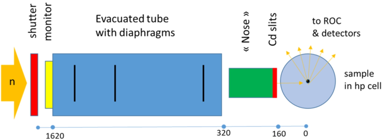
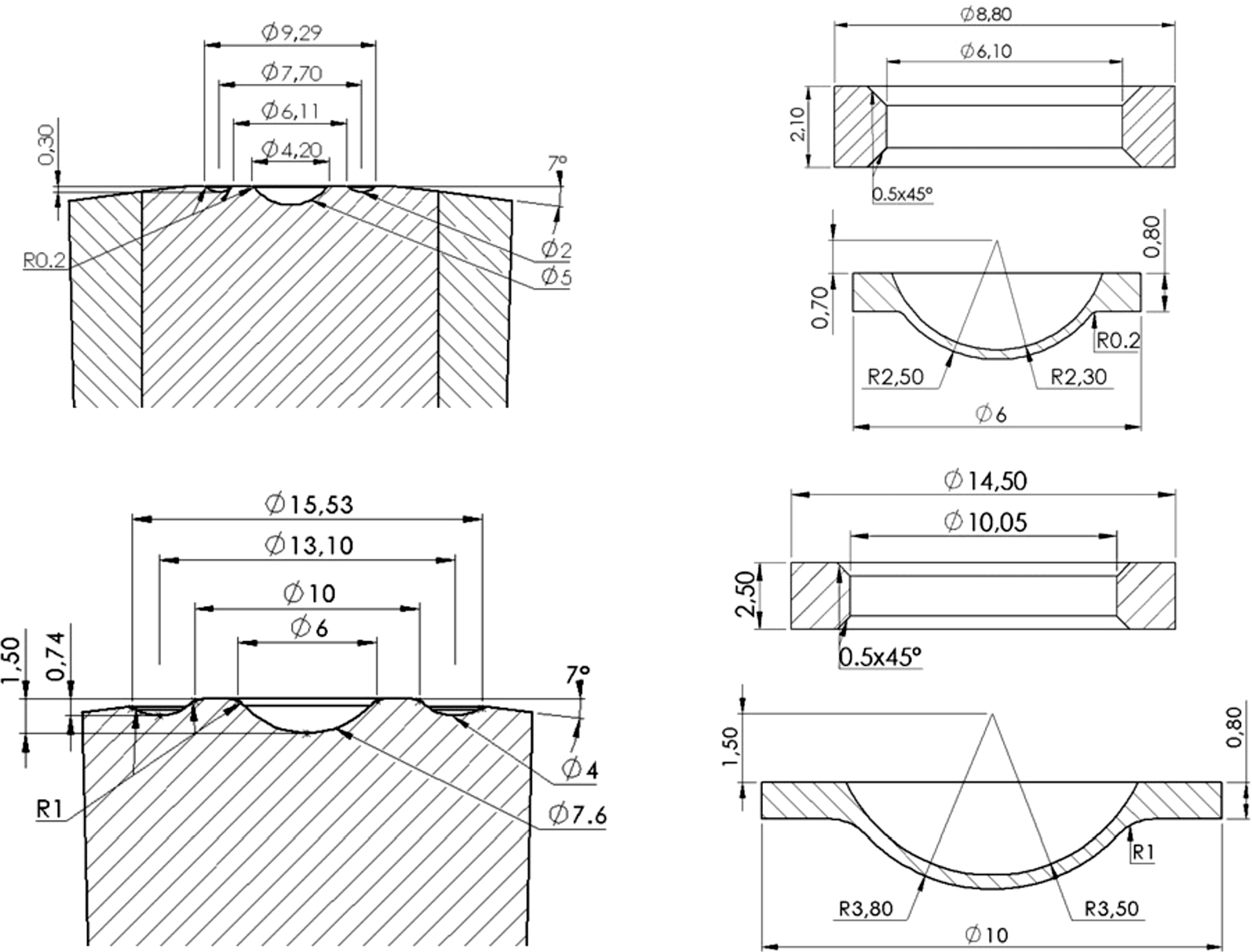
Figure 2 shows drawings of the anvil profile and corresponding encapsulating gaskets [11] which are a result of the SINE2020 development program and to which we refer in this paper. The profile resembles closely to what is known as “double-toroidal” profile (which has been used for neutron scattering to 25 GPa [8]) where the outer toroid has been removed. The starting material of such anvils are wire-drawing sintered diamond dies of type WD960C from Sumitomo. These are smaller than the currently used COMPAX5913 sintered diamond dies from Sandvik Hard Materials and consequently less expensive. Due to the smaller grain size, their hardness and toughness is also superior.
Fig. 2.
Top row: anvil profile (left) and corresponding gaskets (right) for sintered diamond anvils presented in this work (“SD SINE anvils”). Bottom row: standard single-toroidal profile & gaskets for comparison.
3.Identification of background sources
To investigate the sources and composition of background, SINE anvils were used with TiZr gaskets and a mixture of MgO and NaCl as sample. Figure 3 shows patterns obtained with (a) shutter closed, (b) shutter open but beam blocked at r = 320 mm by 15 mm B4C plates plus a 2 mm Cd sheet, (c) beam on anvils (no gaskets), (d) beam on anvils + gasket, and (e) beam on anvils + gasket + sample + pressure transmitting medium (PTM, 4:1 deuterated methanol-ethanol mixture). Note the three strong reflections produced by diamond of the sintered diamond anvils. The anvil gap was in each case 1.6 mm (measured with a gauge or given by the gasket dimensions) which is the situation at 0 GPa, and the conical faces of the anvils were covered by 0.3 mm thick Cd sheets up to the interface between WC and sintered diamond (diam. 16 mm).
Fig. 3.
Diffraction patterns accumulated for 15 minutes each, at different configurations. From bottom to top: shutter closed, shutter open but beam blocked at r = 320 mm (Fig. 1), only anvils, anvils + empty gasket, anvils + gasket + sample + PTM.
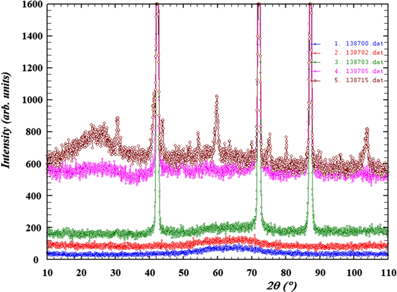
From these data, it becomes clear that the instrumental background (i.e; beam on up to r = 320 mm) represents approximately 15% of the total background. It is similar in size to the contribution of the anvils and the PTM. The major source of background is clearly the TiZr gasket which produces more than half (60%) of the observed neutron background.
In an attempt to reduce the background of the gasket, various tests with improved horizontal collimation close to the sample were conducted (the vertical collimation is guaranteed by the Cd shield on the conical surface of the anvils). The most efficient horizontal collimation was a Cd collimation of 4.5 mm width at a distance of 10 mm from the sample position which reduced the background by approximately 10%, i.e. only insignificantly. The conclusion of these tests was that the collimation implemented on D20 (diaphragms + collimation nose) is already rather efficient and can only be marginally improved. Additional horizontal collimation would necessarily be located as close as possible to the sample and hence be attached to the anvils or the load frame. Such a device would however reduce flexibility since it would exclude a change of rotation angle of the pressure cell with respect to the incident beam. Future improvements could include the development a ROC with smaller gauge volume or some collimation on the diffracted beam side, close to the sample.
4.Data quality: Standard versus SINE anvils
The SINE anvils allow only a ∼50% smaller sample volume compared to the standard single-toroidal anvil profile, i.e. 30 versus 50 mm3. But since the amount of TiZr is also reduced as well as the absorption of the neutron beam due to the reduced gasket dimensions, the signal-to-background ratio was expected to remain approximately equal.
Fig. 4.
Comparison of a diffraction pattern of Fe2O3 collected with cBN anvils with standard geometry (50 mm3 sample volume, blue) and with SINE anvils (30 mm3, red), at low (0–1 GPa, upper panel) and high pressure (∼6.4 GPa, lower panel). The lines through the data (dots) are Rietveld fits. Note that 3 Bragg reflections from diamond were excluded in the red patterns. Accumulation time is 20 minutes in each case.
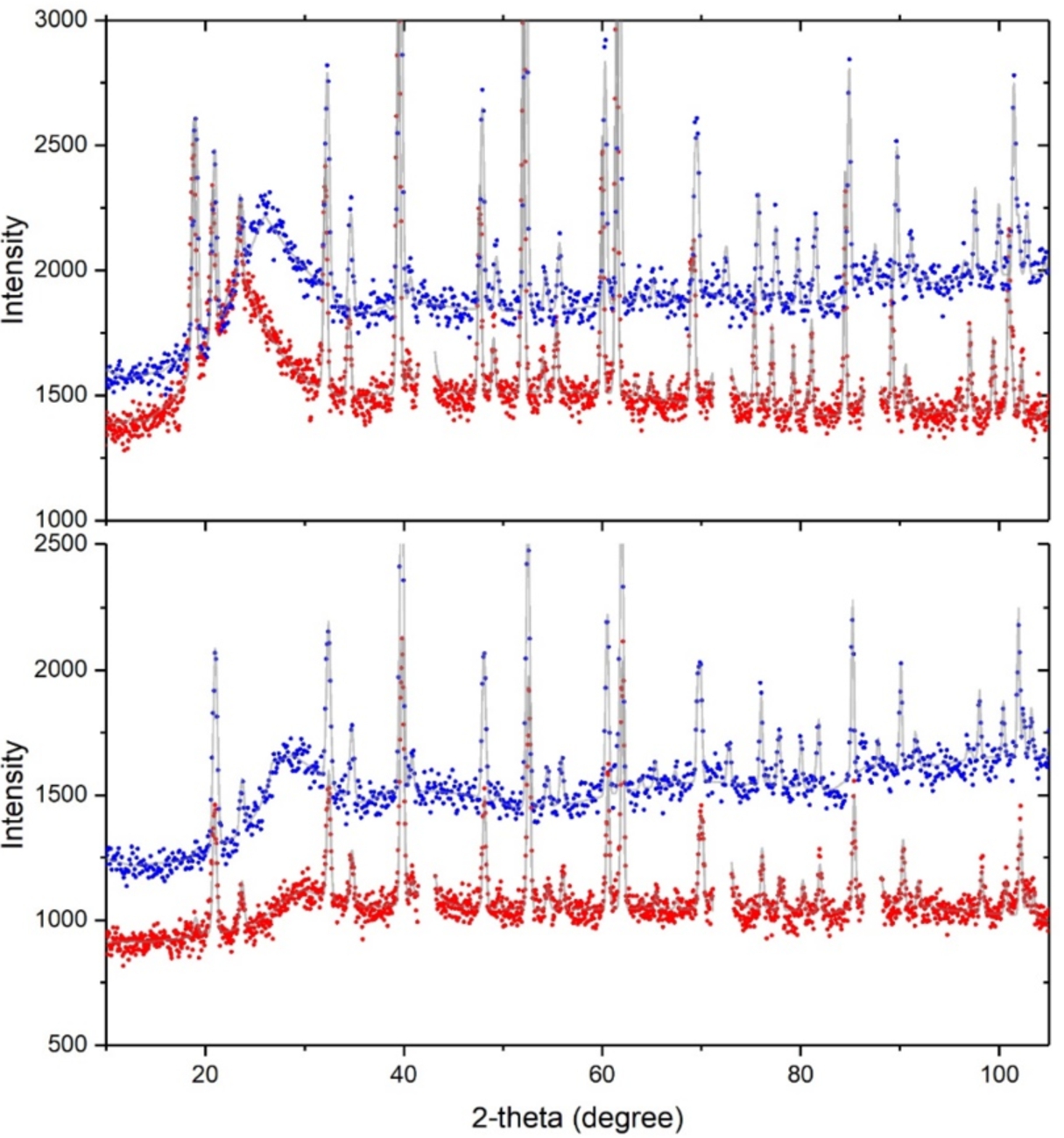
This is demonstrated in Fig. 4 which shows diffraction patterns of Fe2O3 at low pressure ∼1 GPa, in cBN anvils with 50 mm3 sample volume, and SD SINE anvils with 30 mm3 sample volume. The signal-to-background ratio (averaged over all reflections) is very similar for both cases, independent of the pressure (compare upper and lower panel), and might be even more favorable for the latter setup. The only disadvantage appears to be the presence of three strong Bragg reflections of diamond from the anvils. A Rietveld analysis of the pattern where the 3 diamond reflections were excluded show very similar statistical errors on the refined structural parameters. Table 1 gives the refined crystallographic parameters including estimated standard errors (in brackets) which confirm that the precision obtained in the two type of anvils are very similar.
It should be noted that anvils made of SD are obviously more transparent to neutrons than cBN anvils. For the WD960 dies used to machine the SINE anvils, the absorption length for λ = 2.0 Å neutrons is approximately 8 mm [7], whereas for cBN it is 0.1 mm at most. For a given anvil geometry and a given gap between the anvils it means a slightly larger neutron window for SD anvils and hence an increased signal. The gain will be larger for SD anvils with SiC instead of Co binder for which the absorption length is about 50% larger [7]. Since SiC-SD dies are not easily available, expensive to machine, and with mechanical properties likely to be inferior, Co-containing WD960 were used to machine the SINE anvils reported here.
Table 1
Refined structural parameters of α-Fe2O3 (hematite) in single-toroidal anvils cBN and SINE anvils, at low and high pressure (hexagonal setting; θ is the angle of the spin with respect to the c-axis, m is the magnitude of the magnetic moment)
| cBN low p | cBN high p | SINE low p | SINE high p | |
| a (Å) | 5.02638(7) | 5.0101(1) | 5.04325(10) | 5.0017(2) |
| c (Å) | 13.7183(4) | 13.6622(5) | 13.7728(4) | 13.6240(5) |
| z (Fe) | 0.3550(2) | 0.3550(3) | 0.3541(2) | 0.3558(3) |
| x (O) | 0.3059(8) | 0.308(1) | 0.3043(8) | 0.304(1) |
| m ( | 3.92(5) | 4.01(6) | 3.65(5) | 4.00(1) |
| θ (°) | 66(2) | 11(4) | 77(5) | 10(4) |
5.Pressure-load characteristic of SD SINE anvils
This was measured in two runs using a mixture of MgO and NaCl in the first loading and Fe2O3 in the second loading, both with 4:1 methanol-ethanol PTM. The pressure was determined from the known equations of state of NaCl [2], MgO (Birch-Murnaghan equation with B0 = 160 GPa and B′ = 4.2 [4]), Fe2O3 (BM equation with B0 = 201 GPa, B′ = 4.3 [3]). In the run with MgO+NaCl, the quality of the diffraction patterns above 9 GPa degraded, most likely due to the freezing of the PTM. As a result of this, the pressure reading (by Rietveld refinement) from the MgO became less reliable, and the pressure values derived from NaCl appeared to increase more rapidly with load. The plot of Fig. 5 shows also a comparison with standard single-toroidal anvils made of cBN (dashed line). There is a 30% increase in pressure efficiency which is obviously an effect of smaller gasket dimensions.
Fig. 5.
Pressure-load characteristics of SD SINE anvils derived from two loadings with (NaCl+MgO) and Fe2O3, both with 4:1 methanol-ethanol PTM. The dashed line is the typical behavior for standard single-toroid anvils [7].
![Pressure-load characteristics of SD SINE anvils derived from two loadings with (NaCl+MgO) and Fe2O3, both with 4:1 methanol-ethanol PTM. The dashed line is the typical behavior for standard single-toroid anvils [7].](https://content.iospress.com:443/media/jnr/2019/21-3-4/jnr-21-3-4-jnr190120/jnr-21-jnr190120-g005.jpg)
6.Life time of SD SINE anvils
There is some limited information on life time of SD SINE anvils. From a total of 8 loadings, all of them to pressures above 8 GPa, three suffered a violent blow-out. One of them occurred in the upstroke and was a result of overloading the sample space, or a gasket which was too thick. The two others occurred during decompression of the samples shown in Fig. 5 at a load of 28 t. All of the anvils survived without any visible damage. We attribute this robustness against blow-outs to the superior hardness of SD compared to cBN, combined with the fact that the forces on the anvils are generally smaller with the SINE anvils. If this trend is confirmed, routine operation with SD SINE anvils may be less expensive than with cBN anvils, despite their considerably higher initial costs (approximately 2000 € versus 1000 € per anvil).
7.Improved low-temperature Bridgman seal
The ILL low-temperature PE press uses compressed helium as a pneumatic fluid which needs a special seal between the gliding piston and the cylinder. This is a well-known technical challenge given the very low viscosity of helium. In the PE press, it is so far achieved by a Bridgman unsupported seal using a Teflon-Pb-Teflon sandwich with 0.5–2–0.5 mm thickness [9]. Experience over the last 10 years of user operation show that such as seal is perfectly leak tight from ambient temperature to approximately 130 K. But below, small leaks occur frequently at low load (pressure) which often cannot be compensated by the compressor. To improve its reliability, an additional layer of indium was inserted between two separated Pb seals to give a Teflon-Pb-In-Pb-Teflon sandwich with thickness 0.5–1.0–1.8–1.0–0.5 mm as shown in Fig. 6.
Fig. 6.
Low temperature piston (left) of PE VX5 press with its improved Bridgman seal (middle and right). The picture shows the seal after repeated compression to 80 t at 300 K. The layers of Pb and In are not distinguishable.
Initial laboratory tests of this seal in the range 77–300 K showed perfect leak tightness at ambient temperature and no leak down to 90 K if the gas pressure remains above ∼80 bar (∼6 t load, approximately 0 GPa for use with SINE anvils). An increase in load to 200 bar at this temperature did not result in leaks, as expected. A subsequent decrease in load at 95 K led systematically to a leak at ∼100 bar. Such a behavior is typical for Bridgman seals, i.e. leak tightness in the upstroke and occurrence of leaks on pressure release. Further tests were then carried out with the ILL VX5 and its associated cryogenic equipment. With an initial He gas pressure of 200 bar applied at 300 K, no leaks were detected down to 5.3 K.
8.Conclusion and outlook
The results of this work can be concluded as follows:
– Background: The major source of background in neutron scattering in the equatorial plane of the anvils is from the incoherent scattering of the TiZr gaskets. Our data show that there is limited means for improving this, at least at D20. Abandoning null-scattering TiZr as gasket material would be an interesting possibility to explore, in particular for measurements using relatively long wavelengths (2–3 Å), where there are no Bragg reflections at small scattering angles (large d-spacings).
– Anvils: The anvil set up presented here (‘SINE anvils’) has clear advantages compared to the currently used single-toroidal cBN anvils: (a) ∼ 30% higher pressure-load efficiency at comparable signal-to-background level, (b) availability of raw dies, (c) increased life-time and possibly lower costs in long-term use. The additional scattering from diamond seems to be a minor problem. The availability of such anvils would allow the use of smaller PE load frames, for example the 10 kg (mass) VX1 press. With its 50 t capacity it would allow pressures of ∼8 GPa with the same anvils (Fig. 5).
– Bridgman seal: The addition of an indium layer is a major improvement of reliability in the low temperature operation of the PE cell compared to its previous design [7,9].
Acknowledgements
 The work described was performed as part of the world class Science and Innovation with Neutrons in Europe 2020 (“SINE2020”) project, which was funded from the European Union’s Horizon 2020 research and innovation programme under grant agreement No.°654000.
References
[1] | J.M. Besson, R.J. Nelmes, G. Hamel, J.S. Loveday, G. Weill and S. Hull, Physica B 180&181: ((1992) ), 907. doi:10.1016/0921-4526(92)90505-M. |
[2] | M. Brown, J. Appl. Phys. 86: ((1999) ), 5801–5808. doi:10.1063/1.371596. |
[3] | E. Bykova, M. Bykov, V. Prakapenka, Z. Konopkova, H.-P. Liermann, N. Dubrovinskaia and L. Dubrovinsky, High Press. Res. 33: ((2013) ), 534–545. doi:10.1080/08957959.2013.833613. |
[4] | P.I. Dorogokupets and A. Dewaele, High Press. Res. ((2007) ), 431–446. doi:10.1080/08957950701659700. |
[5] | Th. Hansen, P.F. Henry, H.E. Fischer, J. Torregrossa and P. Convert, Meas. Sci. Technol. 19: ((2008) ), 034001, 6 pp. doi:10.1088/0957-0233/19/3/034001. |
[6] | L.G. Khvostantsev, L.F. Vereshchagin and A.P. Novikov, High Temp.-High Pressures 9: ((1977) ), 637–639. |
[7] | S. Klotz, Techniques in High Pressure Neutron Scattering, CRC Press, Boca Raton, (2013) . |
[8] | S. Klotz, J.M. Besson, G. Hamel, R.J. Nelmes, J.S. Loveday and R.M. Wilson, Appl. Phys. Lett. 66: ((1995) ), 1735–1737. doi:10.1063/1.113350. |
[9] | S. Klotz, B. Padmanabhan, J. Philippe and Th. Strässle, High Press. Res. 28: ((2008) ), 621–625. doi:10.1080/08957950802526774. |
[10] | S. Klotz, Th. Strässle and Th. Hansen, Europhys. Lett. 104: ((2013) ), 16001, 5 pp. doi:10.1209/0295-5075/104/16001. |
[11] | W.G. Marshall and D. Francis, J. Appl. Cryst. 35: ((2002) ), 122–125. doi:10.1107/S0021889801018350. |
[12] | “Sample volume” cited throughout the text corresponds to the space enclosed by the encapsulating gasket, i.e. the volume available to the sample plus the pressure transmitting fluid. |
[13] | A.A. Semerchan, N.N. Kuzin, T.N. Davidova and K.Kh. Bibaev, Sov. Phys. Dokl. 28: ((1983) ), 64–65. |


