
High-pressure cell for in situ neutron studies of hydrogen storage materials
Abstract
A high-pressure cell for neutron experiments was developed at Helmholtz-Zentrum Geesthacht (HZG). This cell is designed for the investigation of hydrogen storage materials at pressures up to 700 bar and temperatures up to 500°C. The idea is to have a prototype cell for different neutron scattering methods (diffraction, time-of-flight spectroscopy and small-angle neutron scattering). In this work, we discuss the development and the current state of the high-pressure cell. Furthermore, the deployment of the cell for in situ small-angle neutron scattering measurements on 6Mg(NH2)2 + 9LiH + LiBH4 (6:9:1) at the instrument SANS-1 at Heinz Maier-Leibnitz Zentrum (MLZ) is demonstrated.
1.Introduction
The world economy is facing increasing challenges connected to the transition from fossil fuel energy sources to renewable energy sources. In order to ensure a future of continuous economic growth, it is necessary to search for energy carriers, which allow a synergetic and effective exploitation of renewable energy sources. Hydrogen has the potential to be a sustainable energy carrier [2,7], provided that for its production only carbon free energy sources are used [17,32]. The European Union identified in the “hydrogen economy” a concrete possibility to minimize the CO2 emission in its territory [10,19].
For mobile applications the possibility to store large quantities of energy, and in this context the energy stored in the chemical bonds of hydrogen molecules in a safe and efficient manner, is an essential issue that needs still to be addressed. In this regard, the US Department of Energy (DOE) set the ultimate target of 6.5 wt.% hydrogen capacity for the entire system, including tank and storage material, to ensure a driving range of more than 300 miles (480 km) [24–26]. For solid-state hydrogen storage materials, such as metal hydrides [11,23] and complex hydrides [9,16,27,31], important features are high hydrogen storage capacities (i.e. volumetric and gravimetric), fast loading/unloading kinetics and low operating temperature (<100°C, depending on the heat production of the fuel cell) [11,23].
The challenge that the scientific community must tackle is to design material systems, which possess all these properties at once. For this purpose, the development of tools for the analysis of hydrogen storage materials with X-ray and neutron scattering is of high importance. In fact, such techniques allow acquiring key information on the material microstructural and chemical evolution as well as on the material thermodynamic properties in situ. Ideally, the devices to be developed for investigating hydrogen storage should allow the possibility to perform measurements in a broad range of temperatures and pressures. E.g. onboard hydrogen storage tanks and storage systems used in industry are designed for 700 bar. On this account and considering the application of hydrogen storage materials, the materials characterization up to 700 bar is interesting.
Based on the work carried out by B.S. Clausen et al. [8], Torben R. Jensen et al. designed a cell for in situ solid-gas investigations with X-rays [14,20]. A further development of this X-ray cell, including the gas handling system, is already in use at synchrotron beamlines [4,5,29]. Besides X-rays, neutron scattering is a very powerful technique to probe hydrogen and deuterium, respectively, due to the sensitivity of neutrons towards especially these isotopes [21,33]. The properties of neutrons also include deep penetration of heavy elements, which X-rays cannot facilitate. This makes neutron scattering unique for the analysis of hydrogen storage materials. Therefore, a high-pressure neutron cell was developed based on the model of the X-ray cell. Ex situ SANS measurements with the prototype of this neutron cell were already published by K. Pranzas et al. [30]
In the last decades, complex metal hydrides have been extensively investigated as potential hydrogen storage systems [9,16,23,27,31]. This material class comprises alanates (AlH4−) [3,13], borohydrides (BH4−) [13,28] and amides (NH2−) [12] among others. These compounds possess high hydrogen storage capacities (for compounds containing Na+, Li+, Mg2+ or Ca2+) [35] but their dehydrogenation is hardly reversible. In many cases, full reversibility can be achieved by the combination of complex metal hydrides with metal hydrides and/or additional complex metal hydrides. This approach is the so-called reactive hydride composite (RHC). Among others, the recently developed system Mg(NH2)2–2LiH–LiBH4 has outstanding properties for reversibility and fast kinetics. Depending on the ratio between reactants this ternary system can reversibly store an amount of hydrogen up to 5 wt.% at moderate temperatures [6,12,18,34]. For storage purpose, the system ratio 6:9:1 appears particularly promising given a reaction enthalpy of −36 kJ/molH2 and a gravimetric hydrogen capacity of 4.2 wt% associated to the following reversible reaction path [6,12]:
In the following, we report on the design and development of a high-pressure hydrogen cell suitable for in situ neutron experiments on solid-state hydrogen storage materials. The sample environment has been designed for maximum temperatures and pressures of 500°C and 700 bar respectively. In this work the possibility to perform in situ SANS measurements with the high-pressure cell is demonstrated. The sample 6Mg(NH2)2 + 9LiH + LiBH4 (6:9:1) was measured at SANS-1 at MLZ.
2.Experimental details
The starting chemical compounds used in this work are all commercially available and were purchased in powder form from the following suppliers: MgH2 (95% purity, Rockwood Lithium), LiH (97% purity, AlfaAesar) and LiBH4 (95% purity, Sigma Aldrich). Material handling was carried out in a glove box under a continuously purified argon atmosphere (O2 and H2O levels lower than 1 ppm).
Firstly, Mg(NH2)2 was synthesized by ball milling for 12 h. MgH2 (ball-to-product (BTP) ratio 10:1, 300 rpm) was milled in an atmosphere of 7 bar of NH3 in a gas tight stainless steel vial using a Pulverisette 6 planetary mill (Fritsch, Germany). The Mg(NH2)2–LiH–LiBH4 sample (called henceforth: 6:9:1) was prepared by ball milling the components in the ratio Mg(NH2)2:LiH:LiBH4 = 6:9:1 for 20 h in a stainless steel vial with a BTP ratio of 20:1 at 400 rpm.
The hydrogen content of the material was determined via differential pressure measurements using an in house custom-made Sievert-type apparatus. The differential pressure measurement yielded a hydrogen content of 2.7 wt-%. (Fig. 9a) Although the expected hydrogen capacity was higher [6], after a careful consideration and examination of the material chemistry we decided to proceed further with the material characterization as we did not spot any material alteration with FTIR or of the decomposition temperature measured with DSC.
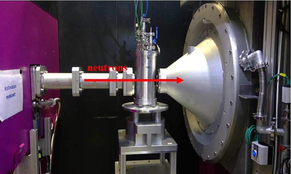
The setup of the high-pressure cell at the SANS-1 instrument at MLZ is shown in Fig. 1. SANS-1 is a neutron instrument that measures neutrons scattered at small scattering angles 2θ or rather at small momentum transfers
For the measurement at 12 Å and 20 m detector distance the background was too high and no sample signal could be detected. Therefore, only the data obtained at 4.5 Å were analyzed. In addition, the reaction kinetics was measured in situ at 20 m detector distance and 4.5 Å neutron wavelength.
Fig. 1.
High-pressure cell setup at the sample position at SANS-1.
3.Design of the high-pressure neutron cell
For the investigation of hydrogen storage materials, a concept design for a high-pressure cell for in situ neutron scattering studies at pressures up to 700 bar and temperatures up to 500°C was developed at Helmholtz-Zentrum Geesthacht (HZG) (Fig. 2).
The basic principle of the neutron cell geometry is a sapphire capillary (Fig. 3) with an outer diameter of 3 mm (1 mm inner diameter) as sample holder. It can be loaded with 4–8 mm3 sample powder. Sapphire is chosen due to pressure and temperature stability as well as to its transparency to neutrons and because it is inert to hydrogen.
Fig. 2.
Setup of the cell for in situ neutron studies of hydrogen storage materials at high temperatures and pressures. The length unit for the dimensions is mm.
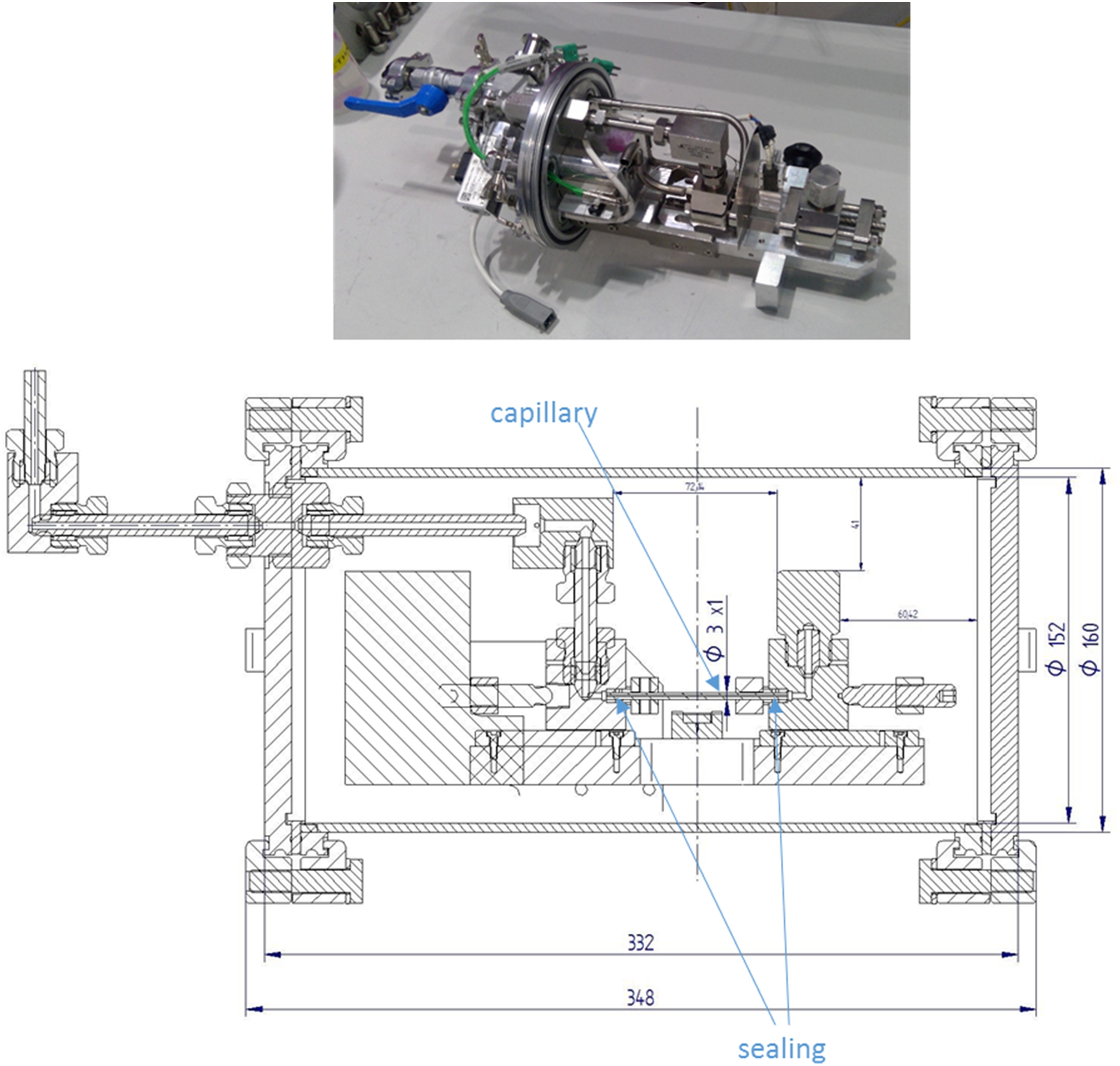
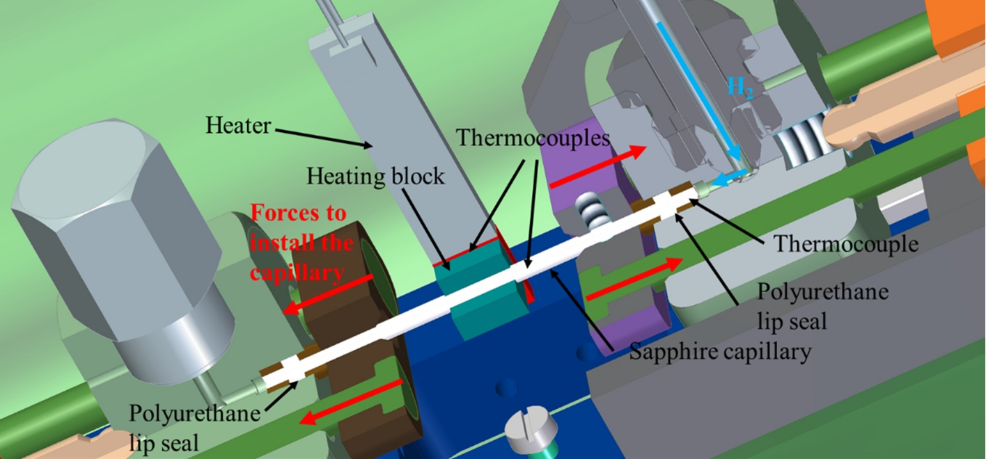
For sealing the capillary, polyurethane lip seals with a maximum operating temperature of 80°C are used. With a metal cone and a supporting ring in-between, the seal is pressed into the housing with forces parallel to the capillary. In this way, the capillary is not exposed to torsion forces, thus reducing the probability of the capillary breakage (Fig. 3). In the narrow housing the polyurethane seal is precompacted and with applied gas pressure the capillary is properly sealed.
Fig. 3.
Sapphire capillary with 3 mm outer diameter and 1 mm inner diameter. The capillary is installed into the housing by pressing the seals with forces parallel to the capillary so that there are no torsion forces on the capillary.
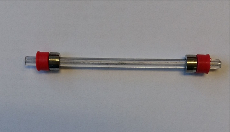
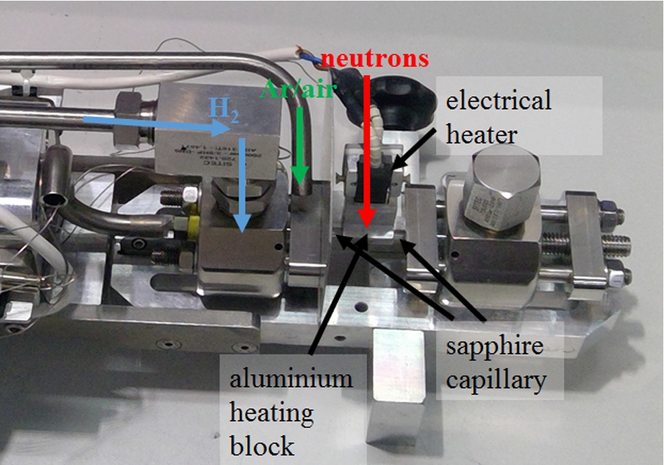
Fig. 4.
Setup of the high-pressure cell. The sapphire capillary is passed through an aluminum heating block to have a better heating transfer from the heater. The neutrons hit the sample parallel to the heater. The cell is flushed with inert gas to prevent explosive hydrogen/oxygen mixture in case of leakage.
Due to a large temperature gradient from the sample position to the seals, the sealing properties of polyurethane seals are maintained at high sample temperatures and pressures up to 700 bar for several hours. In order to ensure sealing stability over long periods of time the use of Kalrez® seals is foreseen.
Because of the high sensitivity of metal hydride-based materials toward moisture and oxygen, the cell was designed to allow the loading of the sample capillary under inert gas atmosphere. Therefore, the cell dimensions (radius: 11 cm, height: 52 cm) have been designed to fit the load lock of a standard laboratory glove box.
For sample heating an electric heating block is used. To obtain a good heating efficiency the capillary is passed through an aluminum block, which has thermal contact to the heater (Fig. 4). Three thermocouples (Type K (NiCr–Ni)) detect the temperatures at different positions: one at the electric heating block for the temperature control, one inside the capillary to measure the sample temperature and one near to the capillary sealing to monitor the temperature of the seals (Fig. 5).
The capillary is fixed at both ends with the polyurethane seals pressed into the metal housings. In the upper housing (right housing in Fig. 5) a thermocouple wire is fixed to be positioned in the middle of the capillary with a feed-through, which is tight against the hydrogen pressure. The thermocouple wire is pushed into the capillary with contact to the sample.
Fig. 5.
The schematic 3D drawing of the high-pressure cell shows the thermocouples measuring the temperature in the capillary, at the heater and at the polyurethane seal. In addition, the concept of the capillary mounting into the housing is indicated with forces parallel to the capillary.
Several devices enhance the safety precautions of the neutron cell. A standardized concept and procedure for handling the setup including an initial leakage testing of the components was developed. During the design process, special attention was paid to minimizing the internal volume of the cell and supply tubes. In addition, the valve to the hydrogen bottle should be closed during the experiment, so that only a small amount of hydrogen is contained in the system. The hydrogen loading station, consisting of a hand-operated pressure generator (SITEC) with additional valves and safety equipment, allows an accurate pressure setting as well as a slow and controlled pressure increase. Permanent hydrogen leakage detection with automatic shutdown of heating in case of leakage/cell damage is used. Instead of this loading station, available gas-handling devices can be utilized as well. Furthermore, the seal temperature is controlled with automatic shut-down if the temperature at the seal exceeds the maximum temperature, which is in the case of the polyurethane seals 80°C. The cell is surrounded by a protection tube made of aluminum (Fig. 2), which is permanently flushed with argon to prevent formation of explosive hydrogen/oxygen mixture in case of a hydrogen leakage. The aluminum tube acts also as a shield against the release of (possibly activated) material/fragments into the environment in case the capillary breaks.
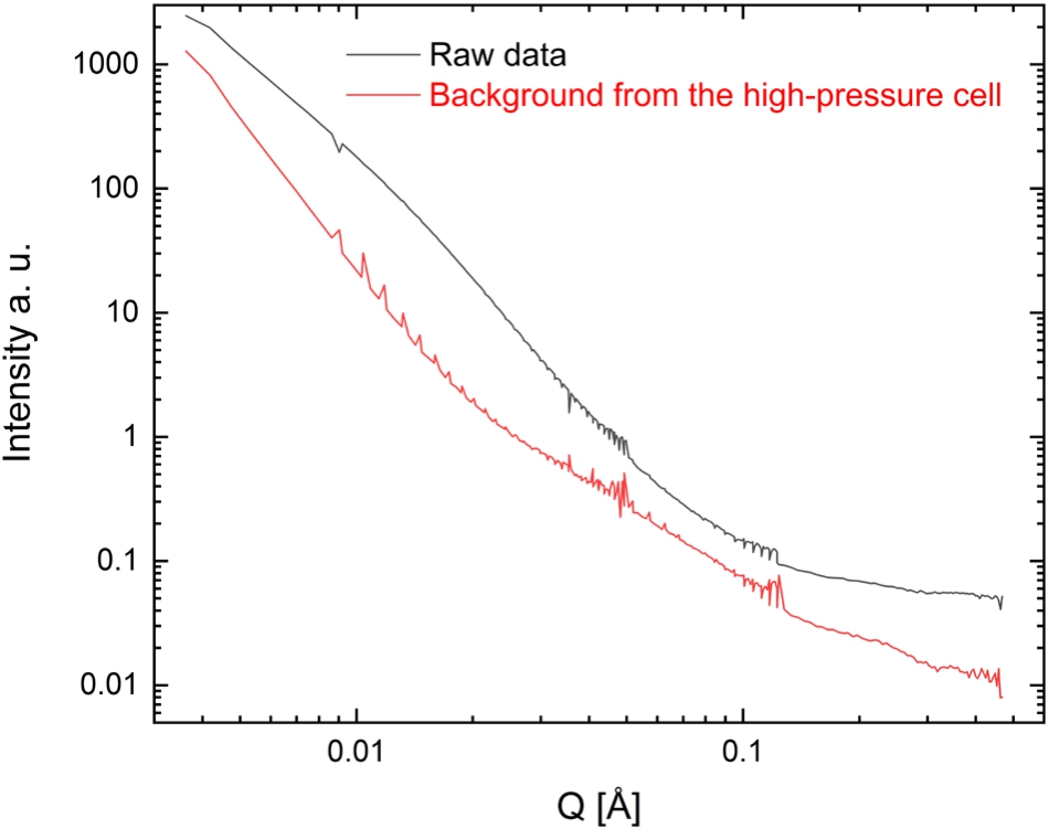
Using the high-pressure cell with the 3 mm-capillaries for small-angle neutron scattering investigations at the instrument SANS-1 at MLZ, the resulting scattering patterns showed a good signal-to-noise ratio even with the surrounding aluminum protection tube. (Fig. 6) At 4.5 Å neutron wavelength 80% transmission was observed.
In Fig. 6 the background of the cell at 170°C and atmospheric pressure is plotted. Because of the low density of hydrogen gas the incoherent cross section from the gas phase is much smaller than that of the sample. Therefore, the incoherent background of hydrogen can be neglected, also at elevated pressures.
Fig. 6.
Small-angle neutron scattering measured with the high-pressure cell at different sample-to-detector distances. The raw data of the sample 6Mg(NH2)2 + 9LiH + LiBH4 and the background signal of the high-pressure cell without the sample are plotted. The raw data was measured at 30°C and 50 bar H2. To obtain the background of the high-pressure cell, the cell was also measured without sample and without capillary at 170°C and atmospheric pressure.
4.Data analysis and results of SANS measurement
The sample 6:9:1 was studied at different experimental settings. The as-prepared sample was in situ measured during stepwise heating to 30°C, 125°C and 170°C at 50 bar H2. At each temperature the whole Q-range of 0.005–0.4 Å−1 was investigated after equilibration. (Fig. 7) In situ SANS measurements were performed during desorption (170°C and 1 bar H2) and absorption reactions (170°C and 70 bar H2) and afterwards the desorbed and absorbed sample was measured in the whole Q-range, respectively. After one cycle, hydrogen was replaced by deuterium and the sample, previously reacted with hydrogen, was cycled with D2. The data reduction and radial averaging were performed with the program BerSANS [22]. Data reduction included normalization to water and background subtraction.
Fig. 7.
(a) The small-angle neutron scattering signal was measured using the high-pressure cell. The data is normalized to water and the background is subtracted. The scattering curves of the sample 6:9:1 are shown at different states of desorption and absorption with hydrogen or deuterium. The incoherent background of the curves (shown in Fig. 7b) is dominated by the high incoherent scattering of 1H and, thus, includes information on the hydrogen content of the sample. The marked area at small Q values, dominated by coherent scattering, was used to measure the in situ scattering signal during each reaction.
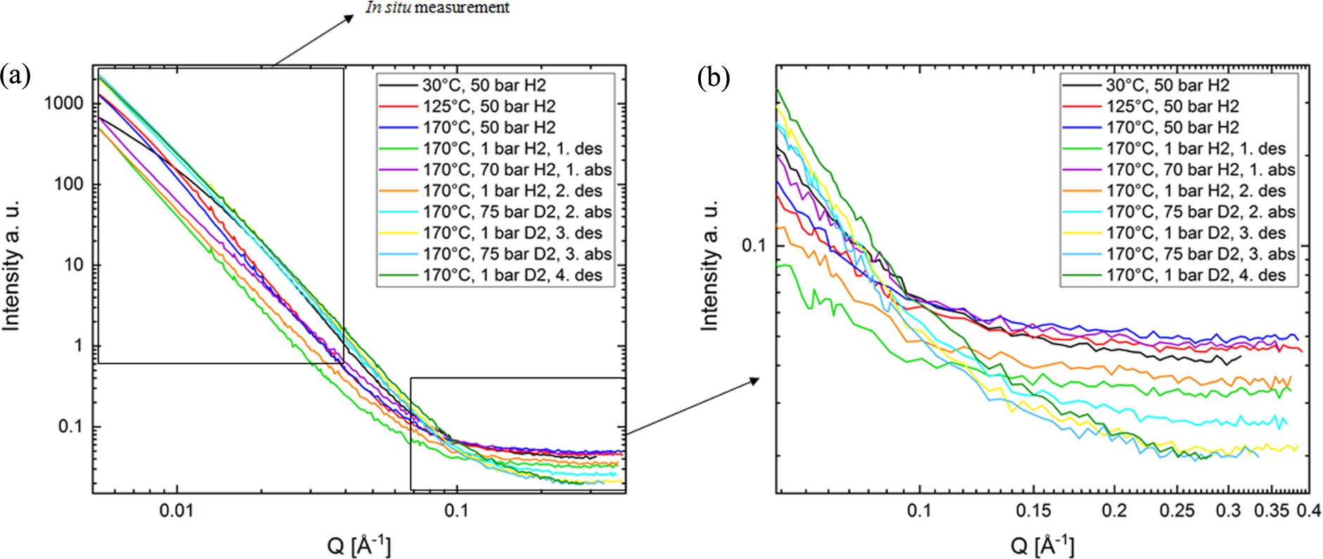
In Fig. 7a the SANS curves at full Q-range of the equilibrated sample are plotted. The plot of the as- prepared sample at 30°C shows the most significant change after heating to 125°C. Upon further heating and even with further cycling the shape and the slope of the curves show only small changes.
The background at high Q of the curves in Fig. 7b is very interesting in terms of hydrogen content of the sample. Because 1H has the highest incoherent scattering cross section at all, the main contribution to the incoherent scattering originates from 1H. The incoherent background in SANS is always not dependent on Q and is constant in the whole Q range. It dominates the signal at large Q. Therefore the incoherent background essentially gives information about the 1H-content in the sample. The intensity of the measured background qualitatively matches well with the experimental sample conditions. The 1H loaded samples have the highest incoherent background. Replacing hydrogen with deuterium, there is an explicit decrease of the background.
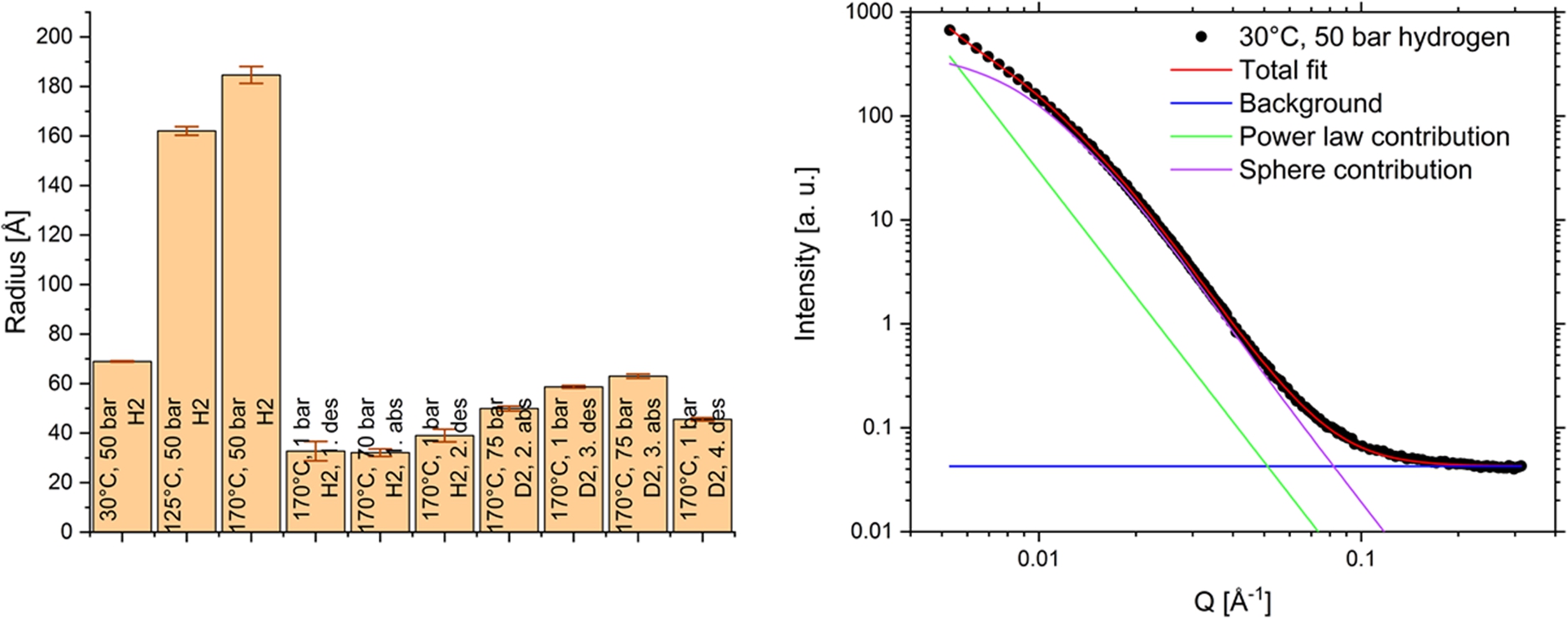
For data analysis of the equilibrium measurements SasView-4.2.0 [1] was used. The particle shape was assumed to be spherical as a first approximation. The data were fitted with the combination of a power law function and a function for spherical structures. (Fig. 8) For further evaluation, a sphere model was used to describe the structural inhomogeneities. Although this model of spheres does not necessarily represent the reality, this first approximation is suitable to follow the changes in the nanostructure of the sample during the reactions and observe the changes of the inhomogeneities depending on the sample condition. The slope of the power law function was fixed to −4 in this first demonstration of the capabilities of the pressure cell to concentrate on the structural inhomogeneities.
As result of the fitting procedure, the structures with a mean “sphere” radius of 75 Å in the as-prepared sample grow to almost triple size during heating from 30°C up to 170°C (Fig. 8) which hints to a coarsening effect. After the first desorption the radius decreases again to very small values and with further cycling it stays constant at small sizes around 30–60 Å. This stable nanostructure is important for a large surface area, which is the basis of a good kinetics in a reversible hydrogen storage system.
Fig. 8.
The small-angle scattering data over the Q-range of 0.005–0.4 Å−1 were fitted with power law and a function for a sphere model. On the right the fit is shown as example for the 30°C and 50 bar H2 condition. The slope of power law is fixed to −4. The fitted sphere radius is for the given example 69.0+/−0.3 Å. The fitting results of the spheres radii for the sample after heating, hydrogen absorption and desorption are shown in the diagram with error bars.
5.Results of the in situ SANS measurement
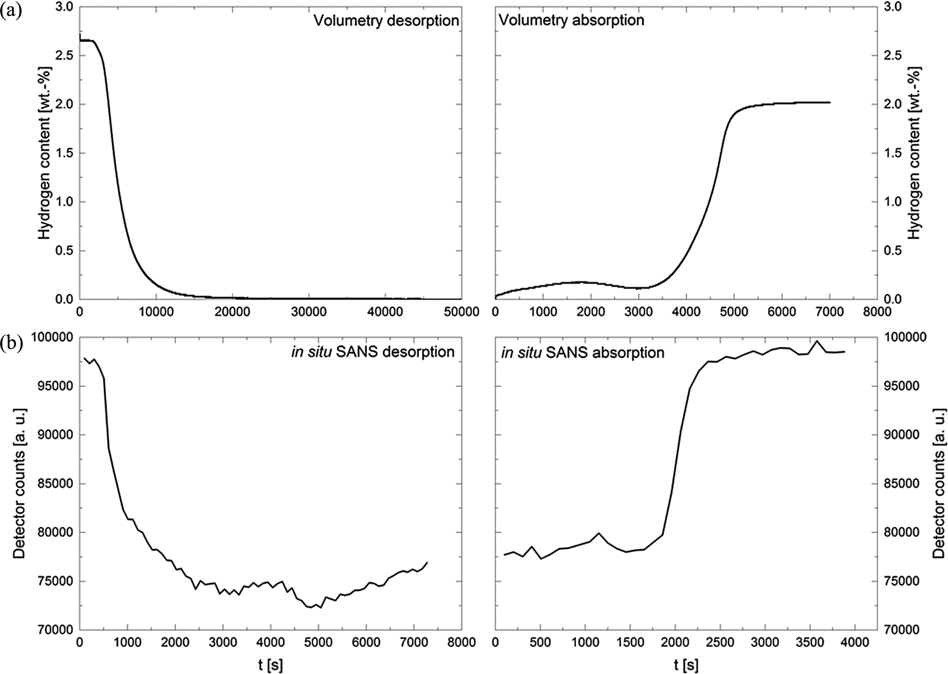
The in situ scattering signal was measured in the Q-range 0.004–0.04 Å−1 (Fig. 7a) during desorption and absorption with a time resolution of 100 s to follow the reaction kinetics. (Fig. 9b) The measurement for 100 s has good statistics and it can also be used for fitting, however, the narrow Q-range of 0.004–0.04 Å−1 restricts the range of the analyzed structures.
The loading experiments with H2 was followed to compare it with the volumetric measurements (Fig. 9a). The reaction kinetics observed with SANS seems faster than the kinetics of the volumetric measurement. (SANS: 64 min desorption and 20 min absorption, volumetry: 257 min desorption and 46 min absorption) The desorption measured with SANS was even 4 times faster than in the volumetric measurement. This observation will be studied in more detail in future. One reason for the discrepancy could be that in both measurements different parts of the sample are probed: In the volumetric measurement more than 100 mg sample were used and hydrogen release and absorption of the whole sample was measured. For SANS less than 100 μg sample were used and the in situ measurement only probed the Q-range 0.004–0.04 Å−1, i.e. only particles with sizes around 16–160 nm contribute to the scattering signal. Assuming that there are bigger particles, which are not probed in the in situ measurement, the reaction kinetics measured with SANS seem faster than the total reaction measured by the volumetric measurement.
Fig. 9.
Comparing reaction kinetics of volumetric investigation with SANS measurement Fig. 9a: volumetric measurement to follow the hydrogen release during desorption reaction and the hydrogen absorption during hydrogenation. Figure 9b: in situ small-angle neutron scattering signal (total counts on detector) of the sample 9:6:1. SANS experiments were performed with the high-pressure cell to follow hydrogen desorption and absorption reaction.
6.Conclusion
The application of the high-pressure cell for in situ small-angle neutron scattering measurements of the 6Mg(NH2)2/9LiH/LiBH4 sample during cycling with hydrogen was successfully demonstrated. The signal-to-noise ratio was excellent. At 4.5 Å neutron wavelength the transmission was 80% and the measurable Q-range was 0.005–0.4 Å−1.
Considering the engineering of the neutron cell, the in situ measurement was performed successfully at the used pressures and temperatures including the safety features. The settings and control of pressure and temperature were easy to handle.
The polyurethane lip seals with maximum temperature of 80°C could be used for several hours at high temperatures and pressures. Nevertheless, to be able to perform long-term experiments at sample temperatures of about 500°C, these seals are planned to be exchanged by Kalrez® seals (Perfluorelastomer (FFKM/FFPM)) with maximum temperatures higher than 200°C.
In addition, with the electric heater and using an aluminum heating block, the maximum temperature is limited to 500°C, therefore other materials for the heating block are tested. Instead of the electric heater, the usage of a laser, a heating lamp with mirror oven geometry or a heat blower are under discussion to reach higher temperatures.
Test measurements showed that the sample volume of the capillaries with 3 mm outer diameter is too small for diffraction experiments at STRESS-SPEC and for quasielastic neutron scattering at TOFTOF. For these kind of investigations sapphire capillaries with 13 mm outer diameter are planned to be tested.
Last but not least, the background of the high-pressure cell hinders SANS measurements with high wavelengths at long detector distances. Therefore, another upgrade is to use a protection tube with a thinner aluminum layer.
Concerning the mentioned issues, the high-pressure cell and the corresponding setup will be further optimized and employed for investigations with different neutron scattering methods (diffraction, quasielastic scattering and small-angle neutron scattering). This cell can be used for the investigation of hydrogen storage materials as well as for other (solid-gas) processes.
Acknowledgements
 This project has received funding from the European Union’s Horizon 2020 research and innovation programme under grant agreement n°654000. We thank the experts in the SINE2020 project from CSEC, IMPMC, ISIS/STFC and LLB for their helpful and constructive advices, and for the discussions concerning the use of high pressure components. The technical support of the colleagues from the technical department at HZG is also gratefully acknowledged. Thanks to André Heinemann (MLZ) for the detailed discussion during the construction process.
This work is based upon experiments performed at the SANS-1 instrument operated by HZG and TUM at the Heinz Maier-Leibnitz-Zentrum (MLZ), Garching, Germany.
This work benefited from the use of the SasView application, originally developed under NSF award DMR-0520547. SasView contains code developed with funding from the European Union’s Horizon 2020 research and innovation programme under the SINE2020 project, grant agreement No 654000.
References
[1] | |
[2] | K. Agbossou, M. Kolhe, J. Hamelin and T.K. Bose, Performance of a stand-alone renewable energy system based on energy storage as hydrogen, IEEE Transactions on Energy Conversion 19: ((2004) ), 633–640. doi:10.1109/TEC.2004.827719. |
[3] | B. Bogdanović and M. Schwickardi, Ti-doped alkali metal aluminium hydrides as potential novel reversible hydrogen storage materials, J. of Alloys and Comp. 253–254: ((1997) ), 1–9. doi:10.1016/S0925-8388(96)03049-6. |
[4] | U. Bösenberg, S. Doppiu, l. Mosegaard, G. Barkhordarian, N. Eigen, A. Borgschulte, T.R. Jensen, Y. Cerenius, O. Gutfleisch, T. Klassen, M. Dornheim and R. Bormann, Hydrogen sorption properties of MgH2–LiBH4 composites, Acta Mater. 55: ((2007) ), 3951–3958. doi:10.1016/j.actamat.2007.03.010. |
[5] | U. Bösenberg, C. Pistidda, M. Tolkiehn, N. Busch, I. Saldan, K. Suarez-Alcantara, A. Arendarska, T. Klassen and M. Dornheim, Characterization of metal hydrides by in-situ XRD, Int. J. of Hydrogen Energy 39: ((2014) ), 9899–9903. doi:10.1016/j.ijhydene.2014.02.068. |
[6] | H. Cao, G. Wu, Y. Zhang, Z. Xiong, J. Qiu and P. Chen, Effective thermodynamic alteration to Mg(NH2)2–LiH system: Achieving near ambient-temperature hydrogen storage, J. Mater. Chem. A 2: ((2014) ), 15816–15822. doi:10.1039/C4TA03505D. |
[7] | H. Chen, T.N. Cong, W. Yang, C. Tan, Y. Li and Y. Ding, Progress in electrical energy storage system: A critical review, Progress in Natural Science 19: ((2009) ), 291–312. doi:10.1016/j.pnsc.2008.07.014. |
[8] | B.S. Clausen, G. Steffensen, B. Fabius, J. Villadsen, R. Feidenhans’l and H. Topsøe, In situ cell for combined XRD and on-line catalysis tests: Studies of Cu-based water gas shift and methanol catalysts, Journal of Catalysis 132: ((1991) ), 524–535. doi:10.1016/0021-9517(91)90168-4. |
[9] | J. Eckert and W. Lohstroh, Hydrogen storage materials, in: Neutron Applications in Materials for Energy, G.J. Kearley and V.K. Peterson, eds, Springer, Switzerland, (1996) , pp. 205–239. |
[10] | P.P. Edwards, V.L. Kuznetsov, W.I.F. David and N.P. Brandon, Hydrogen and fuel cells: Towards a sustainable energy future, Energy Policy 36: ((2008) ), 4356–4362. doi:10.1016/j.enpol.2008.09.036. |
[11] | European Commission (2018). Hydrogen Storage in Hydrides for Safe Energy Systems. Retrieved from https://ec.europa.eu/research/energy/pdf/efchp_hydrogen3.pdf. |
[12] | S. Garroni, A. Santoru, H. Cao, M. Dornheim, T. Klassen, C. Milanese, F. Gennari and C. Pistidda, Recent progress and new perspectives on metal amide and imide systems for solid-state hydrogen storage, Energies 11: ((2018) ), 1027. doi:10.3390/en11051027. |
[13] | L. George and S.K. Saxena, Structural stability of metal hydrides, alanates and borohydrides of alkali and alkali- Earth elements: A review, Int. J. of Hydrogen Energy 35: ((2010) ), 5454–5470. doi:10.1016/j.ijhydene.2010.03.078. |
[14] | B.R.S. Hansen, K.T. Móller, M. Paskevicius, A.-C. Dippel, P. Walter, C.J. Webb, C. Pistidda, N. Bergemann, M. Dornheim, T. Klassen, J.-E. Jørgensen and T.R. Jensen, In situ X-ray diffraction environments for high-pressure reactions, J. Appl. Cryst. 48: ((2015) ), 1234–1241. doi:10.1107/S1600576715011735. |
[15] | Heinz Maier-Leibnitz Zentrum, SANS-1: Small angle neutron scattering, Journal of Large-Scale Research Facilities 1: ((2015) ), A10. doi:10.17815/jlsrf-1-32. |
[16] | M. Hirscher, Handbook of Hydrogen Storage, Wiley-VCH, Weinheim, (2010) . |
[17] | J.D. Holladay, J. Hu, D.L. King and Y. Wang, An overview of hydrogen production technologies, Catalysis Today 139: ((2009) ), 244–260. doi:10.1016/j.cattod.2008.08.039. |
[18] | J. Hu, Y. Liu, G. Wu, Z. Xiong, Y.S. Chua and P. Chen, Improvement of hydrogen storage properties of the Li–Mg–N–H system by addition of LiBH4, Chem. Mater. 20: ((2008) ), 4398–4402. doi:10.1021/cm800584x. |
[19] | Hydrogen Europe. Hydrogen storage. 2019, April 18 retrieved from https://hydrogeneurope.eu/hydrogen-storage. |
[20] | T.R. Jensen, T.K. Nielsen, Y. Filinchuk, J.-E. Jørgensen, Y. Cerenius, E.M. Gray and C.J. Webb, Versatile in situ powder X-ray diffraction cells for solid-gas investigations, J. Appl. Cryst. 43: ((2010) ), 1456–1463. doi:10.1107/S0021889810038148. |
[21] | G.J. Kearley and V.K. Peterson, Neutron Applications in Materials for Energy, Springer, Switzerland, (1996) . |
[22] | U. Keiderling, The new ‘BerSANS-PC’ software for reduction and treatment of small angle neutron scattering data, Appl. Phys. A 74: ((2002) ), 1455–1457. doi:10.1007/s003390201561. |
[23] | Q. Lai, M. Paskevicius, D.A. Sheppard, C.E. Buckley, A.W. Thornton, M.R. Hill, Q. Gu, J. Mao, Z. Huang, H.K. Liu, Z. Guo, A. Banerjee, S. Chakraborty, R. Ahuja and K.-F. Aguey-Zinsou, Hydrogen storage materials for mobile and stationary applications: Current state of the art, ChemSusChem 8: ((2015) ), 2789–2825. doi:10.1002/cssc.201500231. |
[24] | Office of Energy Efficiency & Renewable Energy. Materials-Based Hydrogen Storage. 2019, April 18 retrieved from https://www.energy.gov/eere/fuelcells/materials-based-hydrogen-storage. |
[25] | Office of Energy Efficiency & Renewable Energy, Hydrogen Storage. 2019, April 18 retrieved from https://www.energy.gov/eere/fuelcells/hydrogen-storage. |
[26] | Office of Energy Efficiency & Renewable Energy, DOE technical targets for onboard hydrogen storage for light-duty vehicles. 2019, April 18 retrieved from https://www.energy.gov/eere/fuelcells/doe-technical-targets-onboard-hydrogen-storage-light-duty-vehicles. |
[27] | S. Orimo, Y. Nakamori, J.R. Eliseo, A. Züttel and C.M. Jensen, Complex hydrides for hydrogen storage, Chem. Rev. 107: ((2007) ), 4111–4132. doi:10.1021/cr0501846. |
[28] | M. Paskevicius, L.H. Jepsen, P. Schouwink, R. Černý, D.B. Ravnsbæk, Y. Filinchuk, M. Dornheim, F. Besenbacher and T.R. Jensen, Metal borohydrides and derivatives – synthesis, structure and properties, Chem. Soc. Rev. 46: ((2017) ), 1565–1634. doi:10.1039/C6CS00705H. |
[29] | C. Pistidda, S. Garroni, C.B. Minella, F. Dolci, T.R. Jensen, P. Nolis, U. Bösenberg, Y. Cerenius, W. Lohstroh, M. Fichtner, M.D. Baró, R. Bormann and M. Dornheim, Pressure effect on the 2NaH + MB2 hydrogen absorption reaction, J. Phys. Chem. C 114: ((2010) ), 21816–21823. doi:10.1021/jp107363q. |
[30] | P.K. Pranzas, U. Bösenberg, F. Karimi, M. Münning, O. Metz, C.B. Minella, H.-W. Schmitz, F. Beckmann, U. Vainio, D. Zajac, E. Welter, T.R. Jensen, Y. Cerenius, R. Bormann, T. Klassen, M. Dornheim and A. Schreyer, Characterization of hydrogen storage materials and systems with photons and neutrons, Adv. Eng. Mat. 13: ((2011) ), 730–736. doi:10.1002/adem.201000298. |
[31] | B. Sakintuna, F. Lamari-Darkrim and M. Hirscher, Metal hydride materials for solid hydrogen storage: A review, Int. J. of Hydrogen Energy 32: ((2007) ), 1121–1140. doi:10.1016/j.ijhydene.2006.11.022. |
[32] | J.A. Turner, Sustainable hydrogen production, Science 305: ((2004) ), 972–974. doi:10.1126/science.1103197. |
[33] | G. Walker, Solid-State Hydrogen Storage: Materials and Chemistry, Woodhead Publishing, Cambridge, (2008) . |
[34] | J. Yang, A. Sudik, D.J. Siegel, D. Halliday, A. Drews, R.O. Carter III, C. Wolverton, G.J. Lewis, J.W.A. Sachtler, J.J. Low, S.A. Faheem, D.A. Lesch and V. Ozolins, Hydrogen storage properties of 2LiNH2 + LiBH4 + MgH2, J. of Alloys and Comp. 446–447: ((2007) ), 345–349. doi:10.1016/j.jallcom.2007.03.145. |
[35] | A. Züttel, Materials for hydrogen storage, Materials Today 6: ((2003) ), 24–33. doi:10.1016/S1369-7021(03)00922-2. |

