
Parametric study and design improvements for the target of NOVA ERA
Abstract
The results of a parametric study are presented which was conducted in the framework of the High Brilliance Neutron Source Project (HBS), in order to optimise the target dimensions for a Compact Accelerator driven Neutron Source (CANS). A thin disc shaped target cooled by a water jet was taken as design reference, which was recently published in the Conceptual Design Report for NOVA ERA (Neutrons Obtained Via Accelerator for Education and Research Activities).
For a given target thickness, limited by the ion range in the target material, the cooling fluid pressure and the heat deposition of the ion beam, an optimal diameter of the target disc can be found, for which the occurring stresses are minimised. With the accelerator parameters of NOVA ERA (10 MeV protons with an average power of 400 W on the Target) and with the results of the parametric study, it was possible to design a target, where the occurring stresses are by a factor 3 smaller than the yield strength of the employed beryllium alloy, S-65C VHP.
1.Introduction
Today’s neutron supply for research is mainly provided by fission and spallation sources. While the European Spallation Source (ESS) is currently being built in Sweden, many European research reactors are approaching the end of their life cycle and will be shut down in the near future [2]. This development will dramatically influence neutron provision in Europe and strongly favour major, high impact science topics. The aim of High Brilliance Neutron Sources (HBS) [7] is to complement the scarce high flux facilities by a network of highly scalable low to medium flux sources and to allow for user recruitment, training, education, method development and industrial research and development. The neutron sources conceived in the HBS framework will consist of highly adopted components to suit the requirements of the neutron instruments. The neutrons will be produced by accelerated ions impinging on a suitable target, where they undergo neutron producing nuclear reactions. In contrast to spallation sources, where protons with initial energies ranging from some 100 MeV to several 1000 MeV, HBS will use ions (protons or deuterons) one or two orders of magnitude lower. While the efficiency of ion to neutron conversion in the target is lower than for spallation sources, the aim is to deliver neutrons to the instruments with minimized losses.
For the large range of HBS sources optimized for different fluxes and power levels, adjusted target concepts are required. In this article, we will focus on the target system for a laboratory scale, low flux HBS concept, which was named NOVA ERA (Neutrons Obtained Via Accelerator for Education and Research Activities) [4]. NOVA ERA is a Compact Accelerator driven Neutron Source (CANS) [4,5,7,8], which will produce neutrons by nuclear reactions induced by 10 MeV protons with a suitable target material. A detailed description of the source was recently published in a conceptual design report (CDR) [4]. The design requirements will be studied and described in detail for a 400 W beryllium target, with an expected neutron yield of
2.Basic design considerations
2.1.Target material
For NOVA ERA the first choice for the target material is beryllium. It is one of the most employed materials in CANS today and a lot of experience has been gained with it e.g. at the RANS source in Riken, Japan [8] and at the LENS-facility at Indiana University, USA [6].
Beryllium is known to have a high neutron yield at low ion energies. Some of the beryllium alloys also show good mechanical and thermal properties, e.g. the alloy S-65C VHP, which is refereed to in the structural design guidelines for the future nuclear fusion reactor ITER [3]. Its high thermal conductivity of 200 W m−1 K−1, which is the half of pure copper (401 W m−1 K−1) at 20°C [3] and its high melting point near 1300°C make it suitable for high beam power depositions. Drawbacks of beryllium are its availability and the need of special equipment for machining due to toxic dusts and fumes. Its mechanical strength is acceptable but is quite sensible to the production process and the purchased material grade.
2.2.Target thickness
After choosing the material, the geometry of the target needs to be defined. From LENS [6] we learned, that blistering of the target is a severe problem and already occurs after short operation times. It is mainly caused by primary ions accumulated inside the solid target material. Since a large fraction of the ions which impinge on the target do not react during their path and most of them are stopped in a region which is well known as Bragg-Peak, an effective way to strongly reduce blistering by primary ions is to make the target thinner than the ion range. In Table 1(a) the ranges calculated with the SRIM software [9] for protons and deuterons of different initial energies impinging on beryllium are given. It can be observed that the range is increasing with increasing energy and that deuterons have a much shorter range than protons. In Table 1(b) suitable ion energies for target thicknesses of 0.7 mm, 1.0 mm and 2.0 mm are proposed. These exemplary thicknesses refer to the thicknesses which will be discussed later in the frame of a parametric study.
Table 1
(a) Ranges of protons and deuterons in beryllium and (b) selection of beryllium thicknesses with appropriate suitable energy ranges
| (a) | ||
| Ion | energy | range |
| p | 10 MeV | 0.80 mm |
| p | 20 MeV | 2.78 mm |
| p | 30 MeV | 5.80 mm |
| p | 40 MeV | 9.77 mm |
| d | 10 MeV | 0.67 mm |
| d | 20 MeV | 1.60 mm |
| d | 30 MeV | 3.31 mm |
| d | 40 MeV | 5.57 mm |
| (b) | ||
| Be thickness | p energy | d energy |
| 0.7 mm | 10 …11 MeV | 13 …14 MeV |
| 1.0 mm | 12 …13 MeV | 16 …17 MeV |
| 2.0 mm | 18 …19 MeV | 25 …26 MeV |
2.3.Target cooling
An effective cooling is needed to dissipate the heat generated mainly by the ionization processes in the target. From RANS [8] and LENS [6] two possible solutions are known. While at RANS, a thin layer of beryllium is bonded to a heat-sink, made from vanadium, at LENS a beryllium disc is directly cooled by water. In both cases, the beryllium layer is adjusted to the ion range to avoid blistering, but at RANS, the ions are dumped in the vanadium, which has a higher diffusion coefficient for hydrogen than beryllium. At the LENS facility, the proton beam is dumped into the cooling water.
For NOVA ERA, a simple beryllium disc directly cooled by an impinging water jet from the backside was chosen. In Fig. 1, the basic design of the target assembly is shown. It consists of an elastomer sealed assembly, where the beryllium disc is held in between two flanges. In the picture, the protons from the accelerator are coming from the left side and are impinging on the beryllium target. In the target some of the protons undergo nuclear reactions and neutrons are produced, while the majority of the beam energy is transformed into heat. This requires cooling of the target disc, which is realized by a water jet hitting the target from the right side with a velocity of 3 m/s and is subsequently forced to spread over the target surface through a 1 mm gap. The heated water leaves the target area through a number of concentrically aligned holes. The beryllium disc thickness is chosen in dependence of the ion range and selected according to Table 1(b).
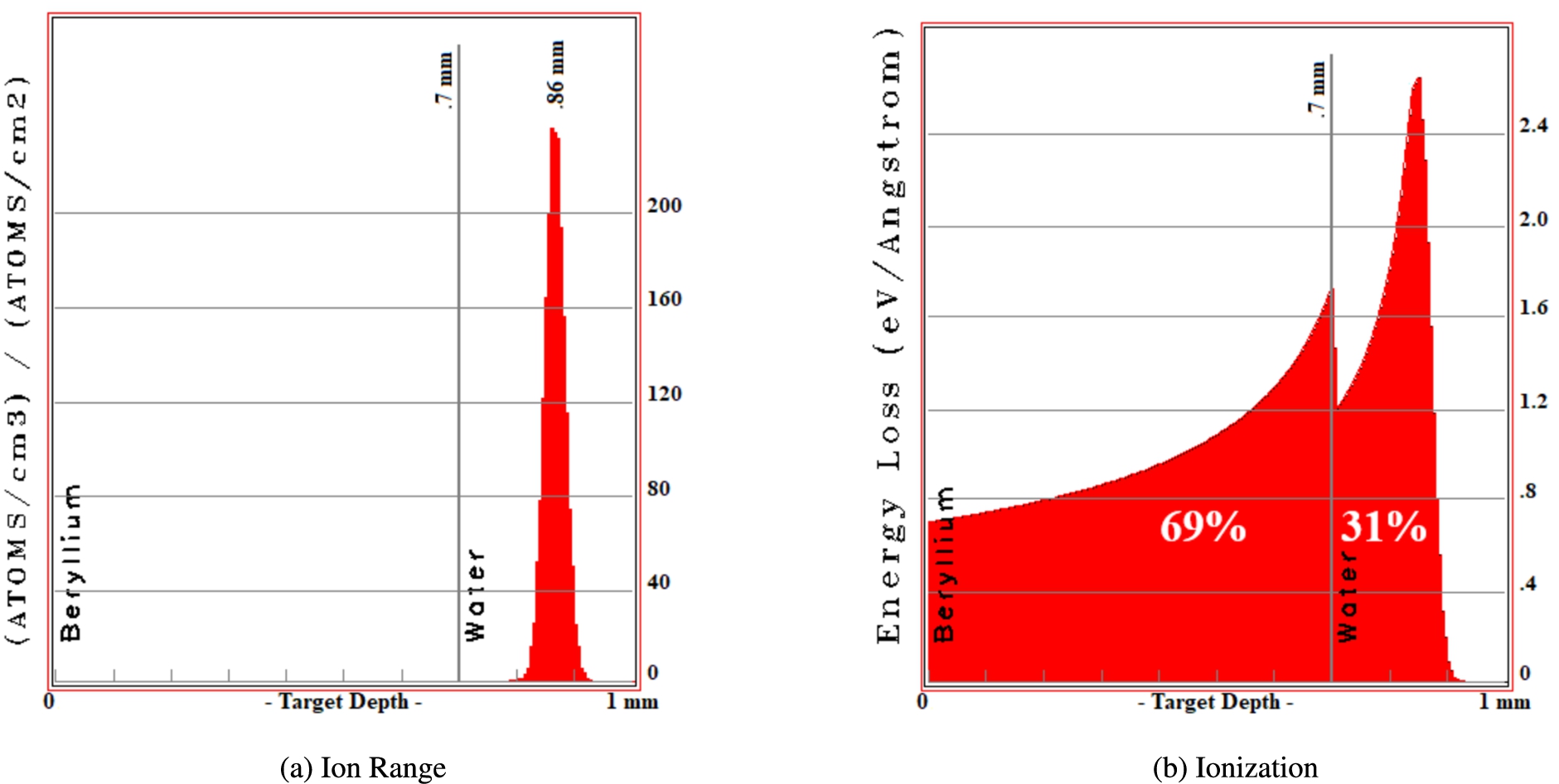
The ion stopping can be investigated in more detail with the help of the Monte Carlo simulation software TRIM [9]. In Fig. 2 the range of the particles and their energy loss
Fig. 1.
Explosion view of the CAD model of the NOVA ERA Design.
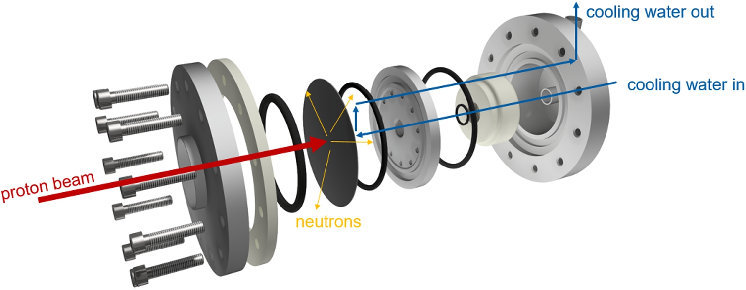
Fig. 2.
TRIM plots of the 10 MeV protons slowed down in 0.7 mm beryllium and stopped in water. 69% of the particle energy is deposited in the beryllium and 31% of the energy are deposited in the cooling water.
2.4.NOVA ERA – concept
With the assumptions made above, a target concept was presented in the conceptual design report for NOVA ERA [4]. The target was conceived for an accelerator system with 400 W beam power and 10 MeV protons. A detailed listing of the accelerator parameters for NOVA ERA can be found in Table 2. A target disc thickness of 0.7 mm and a disc diameter of 80 mm was selected. The flange system requires a peripheral area of the disc in order for it to be held in place. This means that only a smaller concentric area is subjected to the pressure difference of the cooling water and the accelerator vacuum. This unsupported area has a diameter of 40 mm, which is at the same time the diameter of the proton beam tube. The safety margin of the beam spot to the beam tube wall is 5 mm, so that the beam spot has a diameter of 30 mm. These dimensions were selected employing similarly the pressure vessel guidelines AD-2000 for flat ends [1].
Table 2
Parameters of the NOVA ERA accelerator system
| accelerator type: | electrostatic tandem |
| accelerating voltage: | 5 MV |
| proton energy: | 10 MeV |
| peak current: | 1 mA |
| pulse frequency: | 48 Hz to 288 Hz |
| duty cycle: | 4% |
| pulse length: | 139 μs to 833 μs |
| peak power: | 10 kW |
| average power: | 400 W |
ANSYS CFX calculation performed for the above mentioned dimensions resulted in maximum temperatures below 60°C on the vacuum side of the target. The pressure drop and the kinetic pressure on the beryllium were less then 10 kPa for 3 m/s feed water velocity at 22°C.
The thermo-mechanical stress was then calculated using ANSYS mechanical with simplified but conservative input parameters in a stationary case. The 400 W average power were assumed to be homogeneously deposited in the beam spot area and to 100% inside the beryllium layer. The pressure gradient between accelerator vacuum and cooling water was assumed to be 200 kPa. The maximum equivalent stress calculated for the above mentioned dimensions was 197 MPa [4], which is below the yield strength of beryllium S-65C VHP (>236 MPa bellow 100°C) [3].
3.Parametric study
NOVA ERA requires a reliable target system for a likewise reliable day to day user operation. It was therefore decided to study the influence of the disc size on the target stability in more detail and to perform a parametric study. The aim of the study was to find out the dimensions for which the stresses are reduced to a minimum.
Mainly two contributions are affecting the target stability: first, the induced stress due to the pressure difference between vacuum and the cooling water at ambient pressure and second the stress caused by the temperature gradient between the cooled and uncooled target side. The diameter of the target disc is a trade-off. On the one hand a large area allows to increase the area of the beam spot and to reduce the heat density, on the other hand, a larger area means that the forces acting on the surface by the pressure gradient of cooling water and vacuum are larger.
Fig. 3.
Simplified target for the parameter study of a NOVA ERA style target. For the simulations the ratio of the disc diameters, supporting radius and beam radius, was held constant.
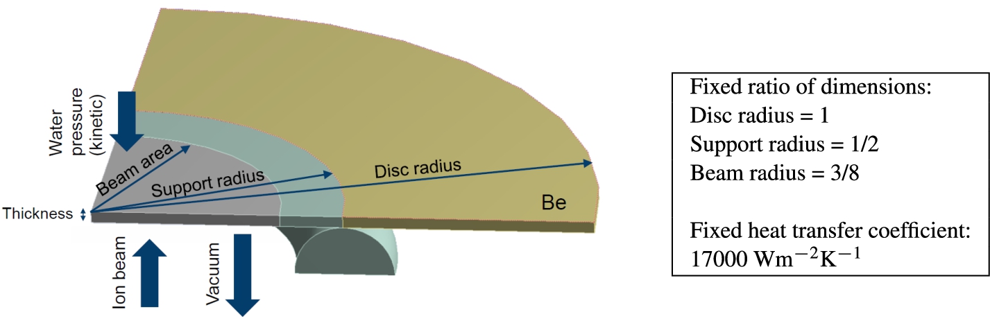
In order to allow for a large number of design points and to limit computer time, the design was abstracted. The study was conducted with a fixed ratio of beam radius, support radius and disc radius where the support radius was 1/2 the disc radius and the beam radius 3/8 the disc radius (see Fig. 3). A heat transfer coefficient of 1.7 · 105 W m−2 K−1 on the cooled target surface was assumed, which was previously calculated with ANSYS CFX and be found to be a realistic value. The temperature of the feed water was assumed to be 22°C.
3.1.Results
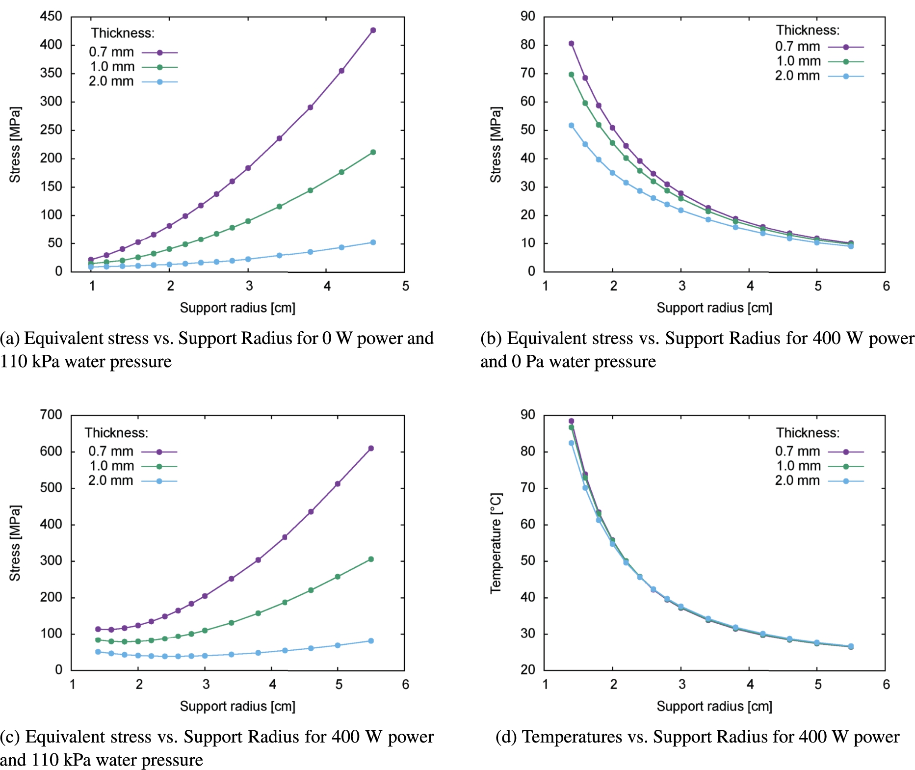
Different load cases were calculated, in order to study the different contributions to the mechanical stress. When subjecting the target to a differential pressure without any heat deposition (Fig. 4(a)), one can observe a rise of the stress for increasing support radius diameters. This is due to the subjected area increasing quadratically with the support radius. For increasing thicknesses the strength of the target increases, allowing larger radii.
In the case shown in Fig. 4(b) the target is subjected to the beam. A heat source of 400 W is introduced, but pressure differences are neglected. Here the stress is decreasing with increasing radius because for constant beam power, the heat density is reduced. This leads to lower temperature gradients and thereby to lower stress.
Figure 4(c) shows the case when the target is subjected to the pressure difference as well as the heat source by heat deposition from a 400 W ion beam. In this case, the resulting stress is a combination of the previously mentioned effects. For a specific parameter set, consisting of contributions from beam power deposition, target layer thickness defined by the ion range and pressure difference, an optimum support radius exists. This minimum is shifted to larger radii for increasing thicknesses. This behaviour can be explained by the influence of the thickness on the pressure-induced stress as well as the stress induced by the temperate gradient. For the shown thicknesses and beam power, the stress induced by the pressure gradient has a stronger impact than the stress induced by the temperature gradient. This can be explained as the maximum temperature occurring in the target disc (Fig. 4(d)) is quickly decreasing with the support radius, while the thickness only has little influence on the maximum temperature.
The results show that for the thin disc shaped target design, an optimum diameter for a given particle energy (target thickness) can be found, and that the stress can be reduced if higher energies are used. With increasing beam power and particle energy, the contribution of the temperature gradient will get more important. Thereby the optimized dimensions are shifted to larger radii, allowing smaller heat deposition densities but causing a larger area subjected to the pressure gradient, increasing its contribution to the stress.
Fig. 4.
Maximum equivalent stress on the target for (a) 0 W beam power and 110 kPa water pressure, (b) 400 W beam power and 110 kPa water pressure, (c) 400 W beam power and 0 Pa water pressure and (d) the temperature for 400 W beam power, for disc thicknesses of 0.7 mm, 1.0 mm and 2.0 mm, respectively.
4.Design optimization
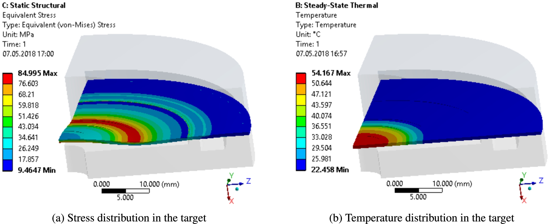
For the conception of NOVA ERA the accelerator parameters were fixed to 400 W average power and a proton beam energy of 10 MeV (see Table 2). From the parametric study we learned that the dimensions presented in [4] can be optimized in order to reduce the stress in the target disc by reducing the area which is subjected to the pressure difference. Therefore simulations were performed assuming realistic model parameters for the NOVA ERA flange type target system with 400 W beam power and 10 MeV protons impinging on a beryllium target. The diameter of the area subjected to the pressure gradient was reduced to 32 mm, according to the results obtained in the parametric study for 0.7 mm target thickness. The corresponding beam spot was then 24 mm in diameter. This time we were using the 69% of the 400 W depositing in the target to get a better picture of the real conditions.
With this input data, the calculation results show that the occurring maximum stresses can be reduced to 85 MPa which is 1/3 of the yield strength of beryllium S-65C VHP [3]. This maximum stress is found at the region of highest bending moment, which is around the support radius where the pressure gradient is the highest. The temperature difference
Fig. 5.
The optimized target concept.
5.Conclusion and outlook
In the first concept, the occurring stresses were kept in the elastic zone. However, with the conducted parametric study we showed that the design for a 10 MeV source with 400 W beam power could be improved. The updated target has now a safety factor of 3 under operation conditions, which is a much better choice, especially for a non structural material like beryllium.
The parametric study also shows that the thin targets required for low energetic ions, are limiting the allowable beam power. With only slightly higher beam energies, the target thickness can be increased and consequently the beam power can be increased likewise. Further more, for each particle energy and beam power combination an optimum target dimension exists. However, further investigations are necessary. In the studies performed, steady state conditions were assumed, whereas in reality, a pulsed source will be employed. But due to the high beam pulse frequency of at least 48 Hz, this is a good first order approximation. However, the peak-powers of single pulses are much higher depending on the duty-factor employed. Furthermore, a realistic beam profile and a energy deposition following precisely the ionization curve should be considered. Fatigue analysis and possible exceptional load cases also need to be investigated.
The results of the parametric study are only valid for the mentioned parameter space and geometry. Towards high power HBS, the influence of the dimensions for a broader range of particle energies and beam powers have to be investigated in more detail if one wants to find the limit of this design. Additional parameters might be relevant. For increasing thicknesses, higher pressure levels will be possible, allowing also higher water pressures and an improved heat transfer to the cooling water. Certainly for higher powers and energies totally different cooling concepts may be the better option e.g with cooling channels inside the target, which will become manufacturable with increasing target thicknesses.
References
[1] | AD 2000-Regelwerk, VdTÜV, 2014. |
[2] | C. Carlile and C. Petrillo, eds, Neutron scattering facilities in Europe: Present status and future perspectives, ESFRI Scripta I (2016). |
[3] | ITER Structural Design Criteria for In-vessel Components (SDC-IC) Appendix A Materials Design Limit Data, Technical report, ITER, 2013. |
[4] | E. Mauerhofer et al., Conceptual Design Report, NOVA ERA (Neutrons Obtained Via Accelerator for Education and Research Activities), A Jülich High Brilliance Neutron Source Project, (2017) . |
[5] | A. Menelle, F. Ott, B. Homatter, B. Annighöfer, F. Porcher, C. Alba-Simionesco, N. Chauvin, J. Schwindling, N.H. Tran, A. Letourneau and A. Marchix, Neutrons Production on the IPHI Accelerator for the Validation of the Design of the Compact Neutron Source SONATE, 2016, arXiv:1612.00237. |
[6] | T. Rinckel et al., Target Performance at the Low Energy Neutron Source, Phys Proc 26: ((2012) ), 168–177. doi:10.1016/j.phpro.2012.03.022. |
[7] | U. Rücker, T. Cronert, J. Voigt, J.P. Dabruck, P.E. Doege, J. Ulrich, R. Nabbi, Y. Beßler, M. Butzek, M. Büscher, C. Lange, M. Klaus, T. Gutberlet and T. Brückel, The Jülich High-Brilliance Neutron Source Project, Eur. Phys. J. Plus 131: (1) ((2016) ), 19. |
[8] | Y. Yamagata, K. Hirota, J. Ju, S. Wang, S. Morita, J. Kato, Y. Otake, A. Taketani, Y. Seki, M. Yamada, H. Ota, Q. Jia and U. Bautista, Development of a neutron generating target for compact neutron sources using low energy proton beams, J. Radioanal. Nucl. Chem. 305: (3) ((2015) ), 787–794. doi:10.1007/s10967-015-4059-8. |
[9] | J.F. Ziegler et al., The Stopping and Range of Ions in Matter, www.srim.org, (2008) . |


