
Improved monochromator concrete shielding for the cold neutron triple-axis spectrometer at HANARO
Abstract
The cold-neutron triple-axis spectrometer (Cold-TAS) installed at CG5, high-flux advanced neutron application reactor (HANARO) has undergone an optimization process in the segmented shield and sample table owing to a slight deformation in 2013. A rapid deformation of the Cold-TAS guide shield was recognized when the reactor was shut down for a long time, and other deformations were confirmed in several monochromator concrete shields in 2015. To ensure safety of the experimental environment, it was decided to redesign the monochromator concrete shield. In the redesigning process, the structure of the segmented and borated polyethylene shield, beam dump, and the shield around the monochromator was changed to improve shielding performance. To improve the load-supporting structure, the outer shape of the monochromator concrete shield was changed from vertical to horizontal. When the mechanical design changed, the proper material, thickness, and density were determined based on the shielding performance results. The improved monochromator concrete shield, Cold-TAS Mark III, was installed at CG5 again. The inspections of the mechanical installation and operations of the sample table and analyzer were completed in the end of 2016.
1.Introduction
The segmented shield structure of the cold-neutron triple-axis spectrometer (Cold-TAS) was improved, and the sample table and analyzer were simplified in 2013 [2,3]. The concrete shield was transformed downward because of the weight of the segmented lead shield. To reduce the total weight of the segmented shield, the height of polyethylene in the top shield was increased to several centimeters, instead of the height of the segmented shield. In addition, an “H” beam was installed under the concrete shield to reinforce load support. The deformation seemed to stop, and the experiment was restarted using the standard sample in 2014. However, the concrete shield deformed again in 2015. The area where the biggest deformation occurred was located in the guide concrete shield. The distance between two guide shield blocks was 45 mm on April 22, but it was 53 mm on August 20. A similar symptom was observed in several areas, and we assumed that this was caused by the following three reasons. The first cause was concrete expansion. The stainless-steel case was fully filled with the concrete mixture, which was mixed with B4C powder and lead ball. The concrete gradually expanded in all directions with time, and the stainless-steel cases was subjected to a tensile force. The second cause was insufficient enforcement to prevent case deformation, and the third cause was the use of spot welding to join the stainless-steel plates, instead of line welding. The stainless-steel case could not keep its original shape owing to the tensile force and broken spot welds. Finally, we judged that stable operation and experimentation would not be possible owing to the deformation of Cold-TAS Mark II. A new monochromator concrete shield (Mark III) was designed and fabricated after disassembling monochromator shield Mark II.
2.Redesign of entire monochromator concrete shield
The Mark III monochromator shield is comprised of two bottom shields, a box shield, left and right shields, a rear shield, top shield, segmented shield set, and beam dump, as shown in Fig. 1. To reuse the dance floor and the guide shield, there were limited changes made to the interface with the monochromator shield. We had tried to improve some aspects in the design process of the Mark III.
![Entire monochromator shield of Cold-TAS: Mark II(Left) and Mark III (Right) [1].](https://content.iospress.com:443/media/jnr/2018/20-3/jnr-20-3-jnr061/jnr-20-jnr061-g001.jpg)
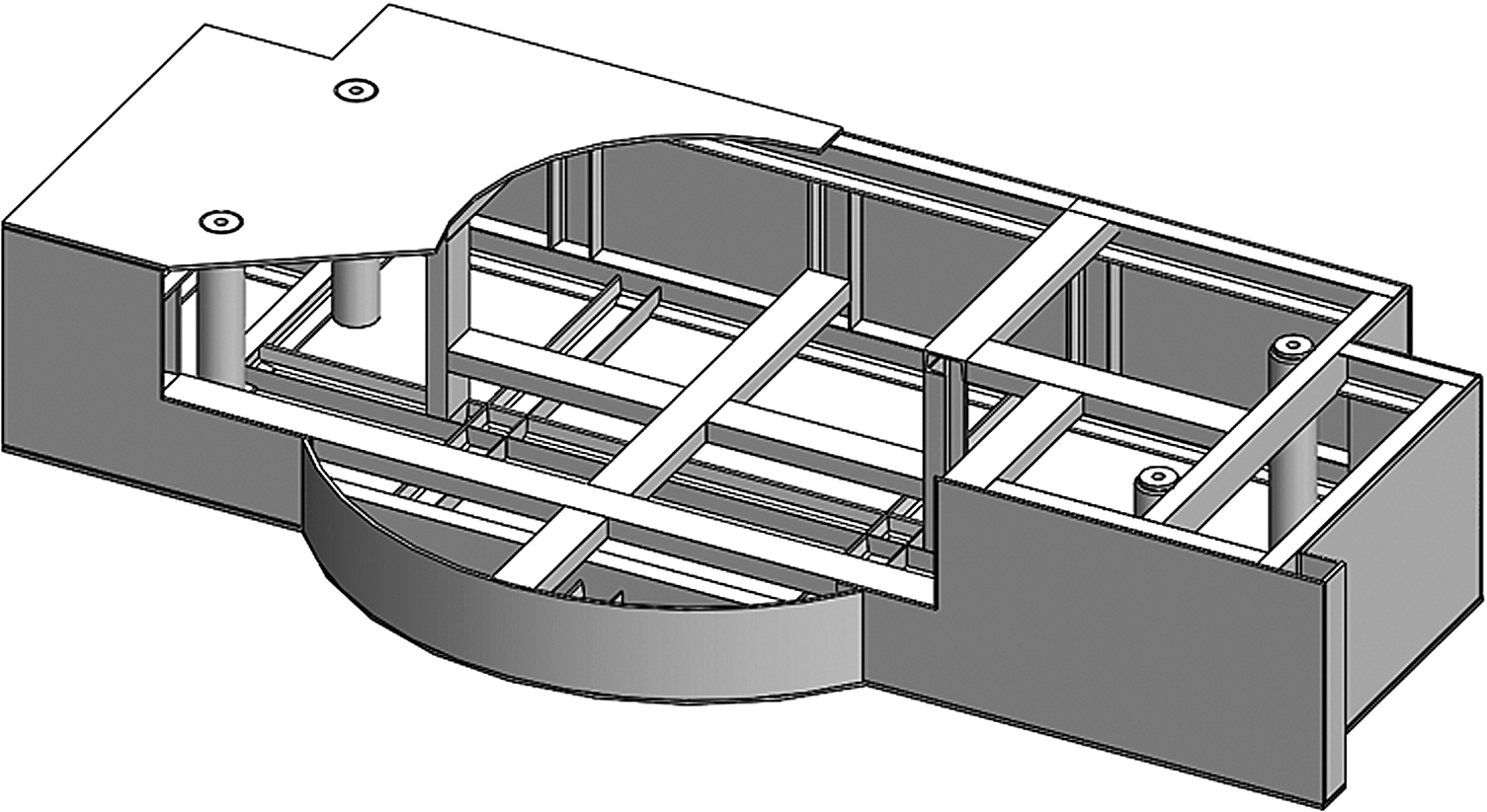
First, the load support and concrete expansion, which caused problems, were considered. The vertical shield of Mark II was unsuitable to support high loads from the segmented lead shields. To improve the supporting structure, the two bottom shields of Mark III were horizontally designed up to the height of the segmented shield set. The bottom shield installed on the floor used the entire floor area and the rotator for the sample table was installed on it. The sample table angle was changed from 25°–125° to 35°–125° to increase the load-bearing area. The part connected to the eye bolts contacted the bottom plate of the shield so that entire load could be borne. To prevent expansion of the concrete, sufficiently strong stiffeners were designed inside the shield, as shown in Fig. 2.
Fig. 2.
Stiffener design in the bottom shield.
Second, the shielding performance was reviewed each time the design changed. The shielding performance was compared with the existing performance in terms of the structure and density using a Monte Carlo simulation (MCNP) [4]. The densities of the top and rear shields were set relatively low owing to sufficient shielding space. As the thickness of the bottom shield where the monochromator is installed was designed to less, the density was set higher than before.
The shapes of the left, right, top, and rear shields were designed similar to Mark II, but not their densities. The entire height of the monochromator shield decreased by approximately 20 cm that is unnecessary volume both shielding and structurally.
3.Part redesign
The part shields were redesigned together when the entire monochromator shield was redesigned. The limitations we had already identified were preferentially improved, and shielding performances were continuously evaluated with the design changes. It was observed that the gamma rays could affect the test results in the previous experimental environment. The design of some parts was changed to solve this problem.
Fig. 3.
Box shield.
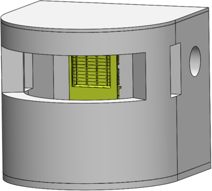
First, the box shield was newly designed in Mark III to block neutron and gamma rays around the monochromator, as shown in Fig. 3. There are four holes that are neutron paths for the guide, beam dump, cables for the moving monochromator, and for the scattered neutrons at the monochromator. The inside of the box shield was covered with borated rubber. Stainless-steel plates were installed on the top and bottom of the box shield. The concrete part of the box shield consists of B4C powder and lead balls with a high density. It is installed close to the monochromator that generates gamma rays owing to interactions with neutrons; hence, high shielding effects can be expected. Owing to the addition of the box shield in Mark III, the thickness of the segmented and borated polyethylene shield was reduced.
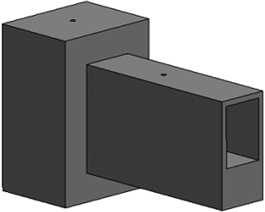
Second, the beam dump that shields the non-scattered neutrons at the monochromator and gamma rays in the direction of neutrons was redesigned as shown in Fig. 4. The elongated nose shown in the figure is simply a beam path fabricated for installation. The larger part constituting the left section in Fig. 4 is high-density mortar containing B4C powder and lead balls. The effect of gamma rays will be decreased because the new beam dump is installed more than 80 cm away from the existing beam dump position.
Fig. 4.
Beam dump.
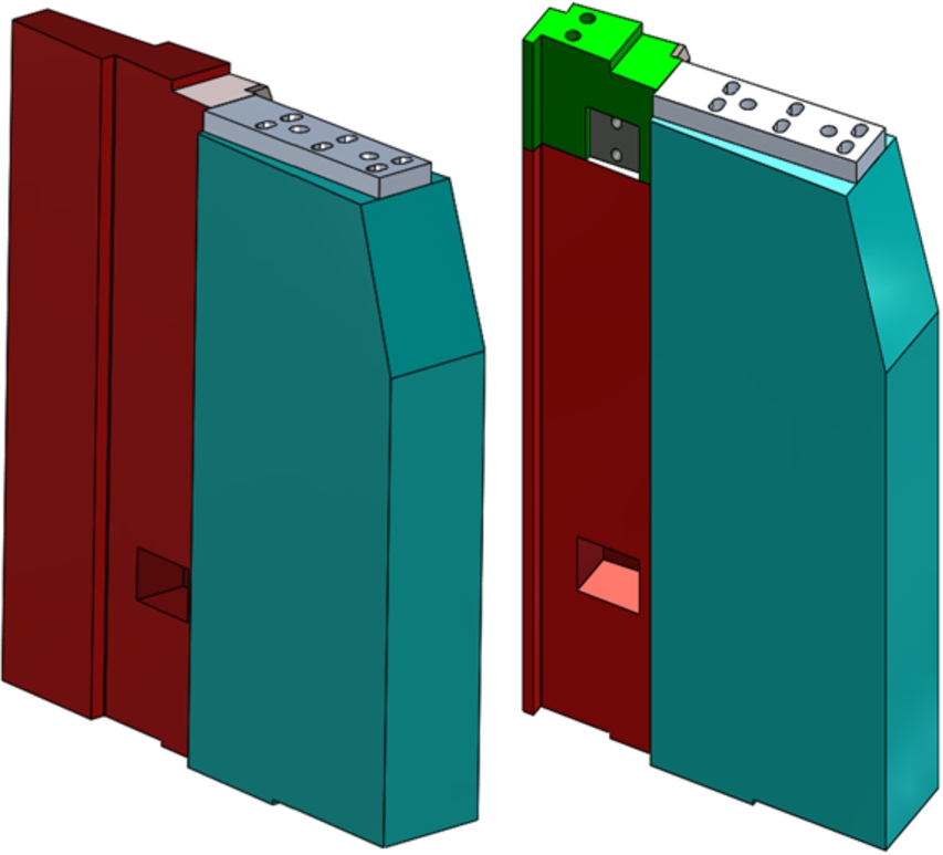
Third, to shield gamma rays leaked to the top of the segmented and borated polyethylene shield, the top 10-cm polyethylene was replaced by stainless-steel. Lead is an effective material for shielding gamma rays, but stainless-steel was chosen for its ease of connection with polyethylene and the air cylinder. The empty space for bolting was filled with the lead block, as shown in Fig. 5.
Fig. 5.
Segmented shield of Mark II (Left) and Mark III (Right).
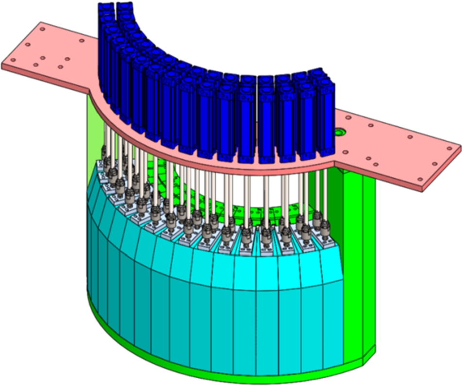
The enhancements in shield design were mentioned so far. We additionally improved one more aspect for easing the installation work. Sixteen segmented shields were individually assembled and dismantled in Mark II and it took a lot of time. To help address this problem, an assembled case was designed to hold the 16 segmented shields together, as shown in Fig. 6. These segmented shields were installed between the newly designed left/right concrete shields and on the stainless-steel plate below. Two rods inside the left and right concrete shields can be connected to the eye bolts to lift the entire segmented shield set. The top stainless-steel plate was connected to air cylinders that could move the segmented shields. The bottom stainless-steel plate of the segmented shield set and its contact surface at the bottom concrete shield were uniquely machined for effective surface contact.
Fig. 6.
Segmented shield set.
![Structure of entire monochromator shield: YZ plane(Left) and XY plane(Right) in MCNP [7].](https://content.iospress.com:443/media/jnr/2018/20-3/jnr-20-3-jnr061/jnr-20-jnr061-g007.jpg)
4.Shielding performance
Figure 7 shows the YZ and XY plane in MCNP viewed from the center of the monochromator in the redesigned structure described above. Although not mentioned above, because it is not included in this redesign, the shielding performances of the small borated polyethylene and lead shield are evaluated together. The small shield set is installed on the sample table and located outside of the segmented shield set. It blocks neutron and gamma rays that are not blocked by the segmented shield without scattered neutrons from the monochromator.
The same density is displayed at the same color. The energy and intensity of neutron source at the monochromator were calculated using a Monte Carlo simulation of triple-axis spectrometers (McStas). The condition without the neutron velocity selector was set for conservative calculations. To check the leakage of neutron and gamma rays, the position of the neutron source was at center of the monochromator and the source was isotropic. For the case study, the distribution of the neutron and gamma flux was confirmed by changing the material (borated polyethylene, stainless-steel, lead, and so on) and structure [4]. The distributions of the neutron and gamma flux on the YZ and XY planes are as shown in Figs 8 and 9. The neutron and gamma flux legend of the graph increases logarithmically.
![Distribution of neutron(Left) and gamma(Right) flux on YZ plane [7].](https://content.iospress.com:443/media/jnr/2018/20-3/jnr-20-3-jnr061/jnr-20-jnr061-g008.jpg)
![Distribution of neutron (Left) and gamma (Right) flux on XY plane [7].](https://content.iospress.com:443/media/jnr/2018/20-3/jnr-20-3-jnr061/jnr-20-jnr061-g009.jpg)
The box shield blocked neutron rays owing to the borated rubber and neutrons distributed only in the neutron path, as shown in Fig. 8. Gamma rays were mostly shielded in the Y direction owing to high density of the box shield. They were distributed in the top and bottom concrete shields past top and bottom stainless-steel plates in the Z direction. The gamma distribution distance on the top shield was longer than the bottom shield because the top shield has a lower density than the bottom shield and is located closer to the source. Gamma rays were blocked at the top of the segmented shield by replacing borated polyethylene with stainless-steel. Neutron and gamma rays did not leak from the shield in the YZ plane.
Most of the neutron and gamma rays were shielded by the box shield in the XY plane as shown in Fig. 9. The neutrons are distributed in the path of neutron scattering from the guide to the beam dump and from the monochromator to the sample. Some neutrons were distributed in the segmented lead shield shown in Fig. 8, but they did not leak out of the shield. The distance of the gamma distribution in the shield is not long owing to the high density of the box shield. The gamma rays in the segmented and borated polyethylene shield were perfectly shielded by the segmented lead shield. Therefore, the new structure and density of the monochromator shield were confirmed to be sufficient for shielding when the neutron source is isotropic.
Performance evaluation of the small shield set indicated that gamma rays leaked through the borated polyethylene of the small shield set because the polyethylene and lead mustache shield was designed in direction of the neutron and gamma paths, as shown in Fig. 7. Even if the neutron source was considered isotropic in this simulation, the neutron beam scattered from the monochromator and the gamma rays generated by the neutron beam moved toward the sample table. The mustache shield will be further improved if the gamma rays are high and affect the experimental result.
5.Shield fabrication and installation
As Cold-TAS will be used for magnetic research, stainless-steel should be used instead of iron-steel in the shield. There are several factors to consider when fabricating the stainless-steel case for the concrete shield. Heat strain occurs during welding between stainless-steel plates and it causes assembly problems. Deformation should be minimized while supporting static and dynamic loads for long periods. Hence, we spent considerable time in welding to avoid surface processing owing to heat strain and deformation. All stainless-steel plates used in the case and stiffener were welded via line welding instead of spot welding. Prior to filling concrete in the case, all cases were assembled and conformed for installation.
The density of concrete was decided according to the location. The density of pure mortar is approximately 2 g/cc, and the density of the mortar mixture having lead and stainless-steel balls is as high as 3–7 g/cc [1]. To prevent a ball from sinking by gravity before hardening, the diameter of the stainless- steel and lead balls was 1–2 mm and mortar mixture was intentionally filled several times.
Five stainless-steel plates were installed on the floor to connect to the bottom shield via bolting. To ensure the flatness of the floor, the floor was coated with epoxy. Two bottom shields and the left/right shields were fastened with bolts and nuts using the holes made during designing. The bolt-connecting part of the rear shield was installed outside of the shield after installing the entire monochromator shield.
The neutron guide, which was removed when the Mark II monochromator shield was removed, was reinstalled in the same position. A part of the neutron guide was installed inside the monochromator shield again. To smoothly move the sample table and analyzer using an air pad, the surface of dance floor of dozens of marbles was polished. The sample table was connected to the rotator installed on the bottom shield, and the analyzer was connected to the rotator on the sample table. A laser tracker was used for mechanical alignment of the sample table and analyzer [5,6].
6.Conclusion
The monochromator shield, which is newly designed eliminating the defects in the existing structure, was installed stably. Mechanical installation and moving inspection of the rotator was completed in the end of 2016. Now, Cold-TAS is under stress testing to check the condition of its components. As HANARO’s operation is unexpectedly delayed, further improvements are planned such as slits, safety devices, and so on. Once the reactor resumes operation, the shielding performance of the redesigned monochromator shield will be measured using a thermos-luminescence dosimeter (TLD). Cold-TAS will be opened to users after the beam test as soon as possible.
References
[1] | J.M. Ryu, Modification of monochromator shielding for cold-neutron triple-axis spectrometer at HANARO, 2017 HANARO Newsletter 8: , 4–5. |
[2] | J.M. Ryu, K.P. Hong, J.M. Sungil Park, Y.H. Choi and K.H. Lee, Shield design of cold neutron triple-axis spectrometer using MCNP6, in: Transactions of the Korean Nuclear Society Spring Meeting, (2014) . |
[3] | J.M. Ryu, K.P. Hong, J.M. Sungil Park, Y.H. Choi and K.H. Lee, Shield design optimization of the HANARO cold neutron triple-axis spectrometer and radiation dose measurement, Journal of Radiation Protection and Research 39: (1), 21–29. doi:10.14407/jrp.2014.39.1.021. |
[4] | J.M. Ryu, J.M. Sungil Park and B.S. Seong, Study of the monochromator shielding block redesign of the HANARO cold neutron triple axis spectrometer, in: Transactions of the Korean Nuclear Society Spring Meeting, (2016) . |
[5] | J.M. Ryu, J.M. Sungil Park and B.S. Seong, Redesign and fabrication of the monochromator shielding of the cold neutron triple-axis spectrometer at HANARO, in: International Conference of Neutron Scattering, (2017) . |
[6] | J.M. Ryu, J.M. Sungil Park and B.S. Seong, Redesign of monochromator shielding of cold neutron triple-axis spectrometer at HANARO, in: Design and Engineering of Neutron Instruments Meeting, (2017) . |
[7] | J.M. Ryu, J.M. Sungil Park, B.S. Seong, S.W. Kim and H.H. Kang, Modification of the monochromator shielding of the cold neutron triple axis spectrometer Mark III, Technical Report, KAERI/TR-6777/2016. |


