
Fuzzy control and wavelet transform-based energy management strategy design of a hybrid tracked bulldozer
Abstract
A new hybrid system of a tracked bulldozer is designed, which primarily consists of an engine-generator set, a battery pack, and a supercapacitor. According to the power requirements of typical working conditions and the output feature of three power sources, a fuzzy control and wavelet transform-based energy management strategy is proposed. Models of the hybrid system are built in Matlab/Simulink and are then transformed into C codes, which are sent to dSPACE. The energy management strategy is verified through HILS (hardware in loop simulation), which demonstrates that the designed strategy is good for increasing the fuel efficiency of the engine and prolonging the working life of the battery pack, which can be used in the real-time control of the hybrid tracked bulldozer.
1Introduction
Along with the deepening of the global energy crisis [7], exhaustion of oil resources, and aggravation of global warming problems [4], electric driving has been widely used in numerous areas, such as the automobile industry, engineering machinery, ships, and harbor hoisting machinery. Thus, the relevant energy management strategy as the core content of vehicle control has also been extensively investigated, including: (1) Rule-based Logic threshold control strategy. Based on the static torque characteristics of engines, threshold parameters are obtained, and logic control rules are built [3]. (2) Fuzzy logic control strategy. Accurate variables are transformed into fuzzy variables, and the fuzzy rules are built in this strategy. Control system outputs are achieved through a series of algorithms, such as fuzzification, fuzzy reasoning, and defuzzification [13]. (3) Local instantaneous optimization strategy. The power consumption of a battery is converted to the fuel consumption of the battery charged by the engine, and the minimum of the equivalent fuel consumption per hour is taken as the objective function to control the output torque of the hybrid system [5]. (4) Global static optimization strategy, such as the Bellman dynamic programming and minimum (or called maximum) principle [6, 15]. The strategy relies on a given driving cycle and has a large amount of calculation, which can not be used in real automobile control and is usually used for providing reference and evaluating other control strategies.
The strategies mentioned above only took the fuel efficiency, emissions, and SOC (state of charge) of the battery and the capacitor into consideration, and they neglected the frequent changes in current and required power, which impose a huge shock on batteries and the engine-generator set.
Aimed at a hybrid system that has three energy sources (an engine-generator set, a battery pack, and a supercapacitor), the energy management strategy is designed using fuzzy control and wavelet transform theory.
2Structure of the hybrid tracked bulldozer
The series electric drive system with two motors driving sprockets on both sides of the tracked dozer was adopted, as shown in Fig. 1.
The system primarily consists of a general controller, an engine-generator set, a rectifier, a battery pack, a supercapacitor, two bidirectional DC/DC converters, and two driving motors and their controllers. The engine-generator set, battery pack, and supercapacitor make up the front power chain, which provides energy for the whole system. The driving motors, motors’ controllers, and sprockets compose the back power chain. There is not a mechanical joint between the front and back power chain, so the electric drive structure is simple and can be easily arranged in the limited space of a bulldozer.
3Energy management strategy design
A tracked dozer usually works in complicated conditions, and its loads change rapidly at a large scale. Using a typical operating condition as an example, the target speed, the working resistance, and the power requirement are shown in Fig. 2.
Among the three power sources of the front power chain, the engine-generator set’s response is slow, and the battery pack is not suitable to charge and discharge in a high frequency or with too heavy of a current [1]; therefore, neither can conveniently handle the instantaneous energy requirement. In contrast, the power density and charge-discharge cycles of the supercapacitor are much higher than those of the battery, which is good for responding quickly to instantaneous energy requirements [9, 10].
Based on the energy requirements of the back power chain and the characteristics of each power source, the energy control strategy is designed by combining fuzzy control with wavelet transform theory, as shown in Fig. 3. The low frequency part of the target power requirement (P com_LF ) was obtained by wavelet transform. If P com_LF < 0, the bulldozer was in the braking state, and the feedback energy would be used to charge the battery packs. If P com_LF > 0, it was delivered to the fuzzy controller where the outputs of the engine-generator set and the battery packs were determined. The total power requirement minus the outputs of the engine-generator set and the battery pack would be the target output of the supercapacitor.
3.1Fuzzy control
A double-inputs and single-output fuzzy control strategy is proposed in the thesis, as is shown in Fig. 4 [2]. The inputs of the fuzzy controller are the engine load f p and the battery SOC, and the output is the power distribution coefficient x f :
(1)
The target outputs of the engine-generator set and the battery packs are:
(2)
(3)
The guidelines for making the fuzzy rules are:
Reduce x f when f p is high and let the battery output power for supplement in time.
Raise x f when f p is low so as to ensure the engine works in an efficient load zone.
Maintain SOC at a value of 0.7 by regulating r f in order to achieve a high charge/discharge efficiency. The membership functions of the engine load f p and the battery SOC after fuzzification are shown in Fig. 5, which are defined as follows:
f p : {S, M, B}, range [0 ∼1] that presents the engine load and varies from 0 to P gen_max.
SOC : {CS, CM, CB, FS, FM, FB}, range [0.6 ∼ 0.8] presents the battery SOC and varies from 0.6 to 0.8.
The definition of the distribution coefficient x f is shown in Table 1, and eighteen rules based on the Mamdani fuzzy control algorithm were designed, as shown in Table 2.
The membership functions of fuzzy controllers greatly affect the efficiency and fuel consumption of electric drive systems. If the power management is regarded as a high dimension nonlinear optimization problem, the membership functions, which are determined by experts’ knowledge, can be seen as the optimization variables [11, 14]. Therefore, in order to further improve the fuel economy, a differential evolution-based hybrid particle swarm optimization algorithm (DEHPSO) is adopted to optimize the fuzzy controller.
PSO (particle swarm optimization) is an effective evolutionary algorithm that comes in two forms: global PSO and local PSO. The velocity and position updating formulas of the global PSO can be expressed as follows [8, 12]:
(4)
(5)
(6)
(7)
Research shows that global PSO has advantages in calculation speed but disadvantages in premature convergence; in contrast, local PSO converges slowly, but the calculation time is too long. Based on this, a hybrid PSO that combines the two algorithms is proposed to improve optimization efficiency. The updated expressions of the hybrid PSO are shown as follows:
(8)
(9)
To increase the population diversity and guarantee global convergence, the particles should have an ability to mutate and crossover in a certain probability. Based on this, this paper introduces the method of differential evolution (DE) to obtain new particles by crossover and recombination between original particles. The process is described in the following:
The method of judging local convergence: The variance of particles’ fitness is selected as the reference for judgment. The variance of fitness in k iteration can be defined as:
(10)
The mutation method: Particles are mutated based on the DE theory, and the position of the new particle in the D dimension can be expressed as follows:
(11)
The crossover method: The mutated particle and its original particle are chosen as the crossover objects, and the cross operation is completed by exchanging position coordinates in random dimensions. The particle position in D dimension after crossover is:
(12)
The elimination method: After the mutation and crossover operations, the newly created particles are compared to the original particles in order to eliminate those that have a worse fitness; this process can be described as follows:
(13)
The specific flow of DEHPSO is described in Fig. 6.
The optimization target in this paper is to minimize the fuel consumption after a certain working time, and SOC is also an important factor that influences the fuel consumption (when the fuel consumption is forcibly reduced, the battery undertakes more tasks, and the SOC of which will decrease); therefore, variance of SOC (ΔSOC) should be limited in a short interval to ensure the optimization effect. The optimization function (or fitness value) can be expressed as follows:
(14)
The optimized membership functions are shown in Table 3 and Fig. 7.
3.2Wavelet transform
As the power requirement signal is discrete in one dimension, the discrete wavelet transform (DWT) is used to decompose it in different levels. The DWT and IDWT (inverse discrete wavelet transform) are:
(15)
(16)
Compared to other common wavelets, the generating function of the Haar wavelet has the shortest filter length in the time domain, and the transformation and the inverse transformation are the same. Thus, the decomposition process of the Haar wavelet is much simpler than those of other wavelets, which makes it feasible to extract transient signals in real-time control of the electric drive bulldozer. The expression of the Haar wavelet is:
(17)
A two-channel filter bank based on the Haar wavelet was adopted. The original signal x (t) is decomposed into reference signals and detail signals by a low-pass filter H 0 (z) and a high-pass filter H 1 (z), and the signal is rebuilt by a reconstruction filter bank [G 1 (z) , G 0 (z)] T . The decomposition and reconstruction processes of the 3-order DWT based on the Haar wavelet are shown in Fig. 8. Only eight sampling points of power requirement (which is composed of one point in current time and the previous seven points) are necessary for the 3-order DWT. There is no need to know the whole working condition in advance, which is superior to Fourier transform. The DWT could also be used for processing signals in unknown working conditions.
4Modeling and simulation
4.1HILS platform
The simulation platform of the hybrid system was built in MATLAB/Simulink, which primarily consists of a control strategy model, an engine-generator set model, a battery pack model and its DC/DC model, and a supercapacitor model and its DC/DC model, as shown in Fig. 9.
4.1.1Engine-generator set model
The engine and generator are modeled as a whole according to the rotation speed relationship between them. The generator is connected to the DC bus through a three-phase bridge uncontrolled rectifier with a filter capacitor, and the equivalent circuit of PMSM (permanent magnet synchronous motor) with a bridge rectifier is shown in Fig. 10.
The internal resistance and torque losses of the generator are neglected, and the voltage of the DC bus and the electromagnetic torque are:
(18)
where K e ω g is the induced electromotive force, K x ω g is the equivalent resistance, and I D C is the current of the DC bus.
4.1.2Battery pack model
As the electric energy storage unit of the electric drive system, the main functions of the battery pack are supplying power when the engine is unable to respond to the power requirement and recycling the braking energy of the driving motors. The battery pack provides or accepts energy according to the control signals from the general controller, and it sends signals of SOC in current time and the maximum charge-discharge power limit to the general controller. The battery pack is connected to the DC bus through a DC/DC converter. The equivalent resistance model is adopted, as is shown in Fig. 11. The battery pack is equivalent to an ideal voltage source with a series resistance:
(19)
Both the open-circuit voltage V bat and the equivalent resistance R s vary by changes in the SOC and the temperature; however, the effect of temperature is small and can be neglected when modeling. V bat and R s are obtained through lookup tables by inputting the SOC, and the SOC of the battery pack is calculated by the ampere-hour integration approach:
(20)
4.1.3Supercapacitor model
The equivalent RC model is adopted and is shown in Fig. 12. Based on the equivalent circuit, the output current is:
(21)
The series resistance of the supercapacitor changes little when charging and discharging and is usually taken as a constant. The parallel resistance is small, which has less of an effect on the circuit and is usually ignored. The SOC of the supercapacitor is:
(22)
By choosing driver input equipment and testing the controller as hardware, the HILS platform is established based on dSPACE Micro-AutoBox 1401/1504, and the structure of which is shown in Fig. 13. Models of the engine-generator set, the battery, and the supercapacitor built in host computer are compiled and downloaded into dSPACE by the Matlab/RTW interface. The control strategy model is first compiled by Matlab/Stateflow and then transcoded by TargetLink and downloaded into the tested controller.
After processing of A/D conversion, the controller receives the signals and communicates with dSPACE by USB CAN. The hardware components of the HILS platform are shown in Fig. 14. To obtain the driving states of the dozer, a monitor interface is built in a monitor terminal based on Controldesk, which is shown in Fig. 15.
4.2Simulation results
The power distribution result of the front power chain is shown in Fig. 16. As the main power source, the engine-generator set is expected to provide most of the power requirement. As the auxiliary power unit, the battery pack affords power when the engine-generator’s output is not sufficient and recycles energy when braking, which plays a role in peak shaving and valley filling. The supercapacitor, which has the advantage of fast charging and discharging, is required to respond to the instantaneous power requirement.
The SOC curves of the battery pack and the supercapacitor are shown in Fig. 17. It is observed that the battery SOC changes little and essentially stabilizes around 0.7, and the supercapacitor SOC changes in a wide range from 0.4 to 0.75. The supercapacitor’s advantages of fast discharging and deep discharging are exhibited. The charge-discharge voltage and current of the battery and the supercapacitor are shown in Figs. 18 and 19, respectively. The charge-discharge current of the battery varies from –100 A to 250 A, which is more stable than that of the supercapacitor that varies from –200 A to 400 A.
5Conclusions
The fuzzy control and wavelet transform-based energy management strategy of the hybrid tracked bulldozer is proposed, which realizes the energy distribution among the engine-generator set, battery pack, and supercapacitor according to the changing frequency of the required power and thus improves the system performance and prolongs the service life of the components. Modeling and HILS are conducted, and the results show that the designed strategy can properly distribute power and is suitable for the real-time control of a hybrid dozer.
References
1 | Jossen A (2006) Fundamentals of battery dynamics Journal of Power Sources 154: 2 530 538 |
2 | Mamdani EH, Assilian S (1975) An experiment in linguistic synthesis with a fuzzy logic controller International Journal of Man-Machine Studies 7: 1 1 13 |
3 | Banvait H, Anwar S, Chen Y (2009) A rule-based energy management strategy for plug in hybrid electric vehicle Proc Am Control Conf, St Louis 3938 3943 MO, United States |
4 | Ren JW, Xiao CD, Hou SG (2009) New focuses of polar ice-core study: Neem and dome A Chinese Science Bulletin 54: 6 1009 1011 |
5 | Wu J, Zhang Ch, Cui N (2008) Real-time energy management of parallel hybrid electric vehicle based on BP neural network Electric Machines and Control 12: 5 610 614 |
6 | Perez LV, Bossio GR, Moitre D (2006) Optimization of power management in an hybrid electric vehicle using dynam-ic programming Mathematics and Computers in Simulation 73: 1 244 254 |
7 | Wachtmeister M (2013) Overview and analysis of environmental and climate policies in China’s automotive sector The Journal of Environment & Development 22: 3 284 312 |
8 | Castillo O, Martínez-Marroquín R (2012) Comparative study of bio-inspired algorithms applied to the optimization of type-1 and type-2 fuzzy controllers for an autonomous mobile ro-bot Information Sciences 192: 19 38 |
9 | Strzelecki RM, Benysek G (2008) Energy Storage Systems 267 295 Springer London, England |
10 | Spyker RL, Nelms RM (2000) Analysis of double-layer capacitors supplying constant power loads IEEE Transactions on Aerospace and Electronic Systems 36: 4 1439 1443 |
11 | Precup Radu-Emil, Tomescu Marius L. (2012) Iterative per-formance improvement of fuzzy control systems for three tank systems Expert Systems with Applications 39: 9 8288 8299 |
12 | Yacoub RR, Bambang RT (2014) DSP implementation of combined FIR-functional link neural network for active noise control International Journal of Artificial Intelligence 12: 1 36 47 |
13 | Wahsh S, Hamed HG, Nashed MNF (2008) Fuzzy logic based control strategy for parallel hybrid electric vehicle, Taka-matsu Proc IEEE Int Conf on ‘Mechatronics and automation’ 27 31 Japan |
14 | Xie XL, Sh Li J (2014) Improving response-time perfor-mance in acute care delivery: A systems approach IEEE Transactions on Automation Science and Engineering 11: 4 1240 1249 |
15 | Gu Y, Yin C, Zhang J (2007) Optimal torque control strategy for parallel hybrid electric vehicle with automatic mechanical transmission Chinese Journal of Mechanical Engineering (English Edition) 20: 1 16 20 |
Figures and Tables
Fig.1
Structure of the hybrid tracked bulldozer.
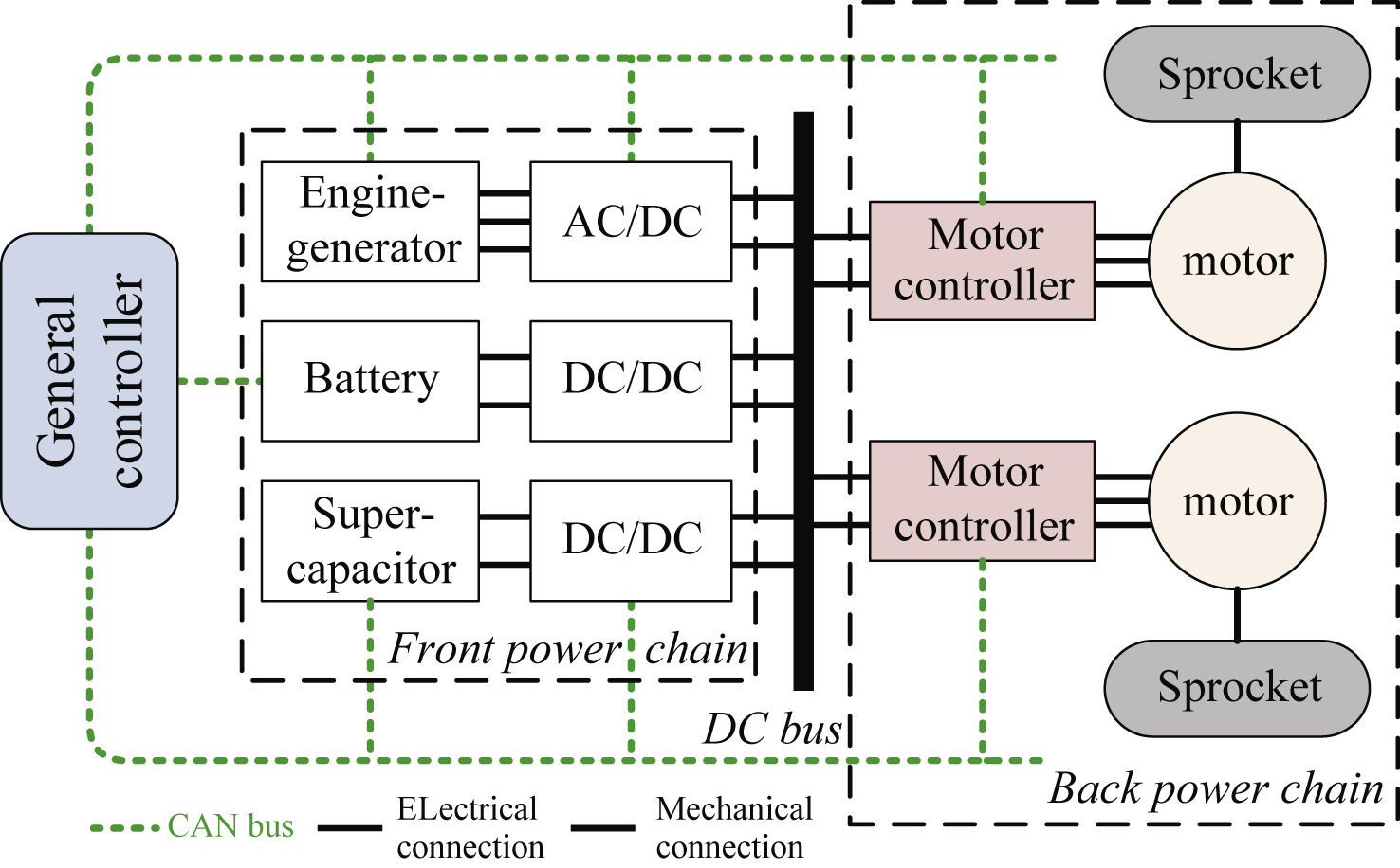
Fig.2
A typical operating condition of a tracked dozer.
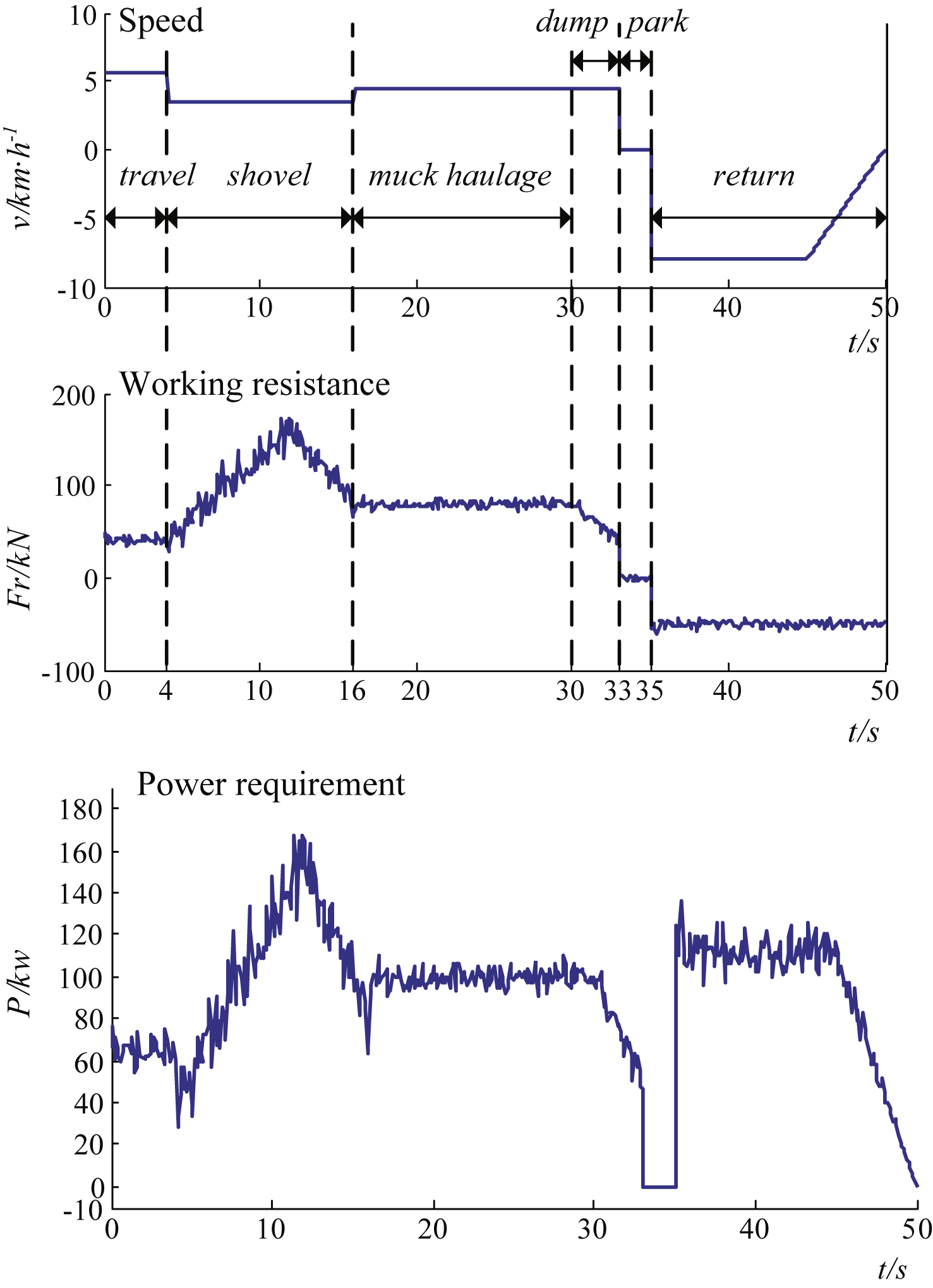
Fig.3
Fuzzy control and wavelet transform-based energy management strategy.
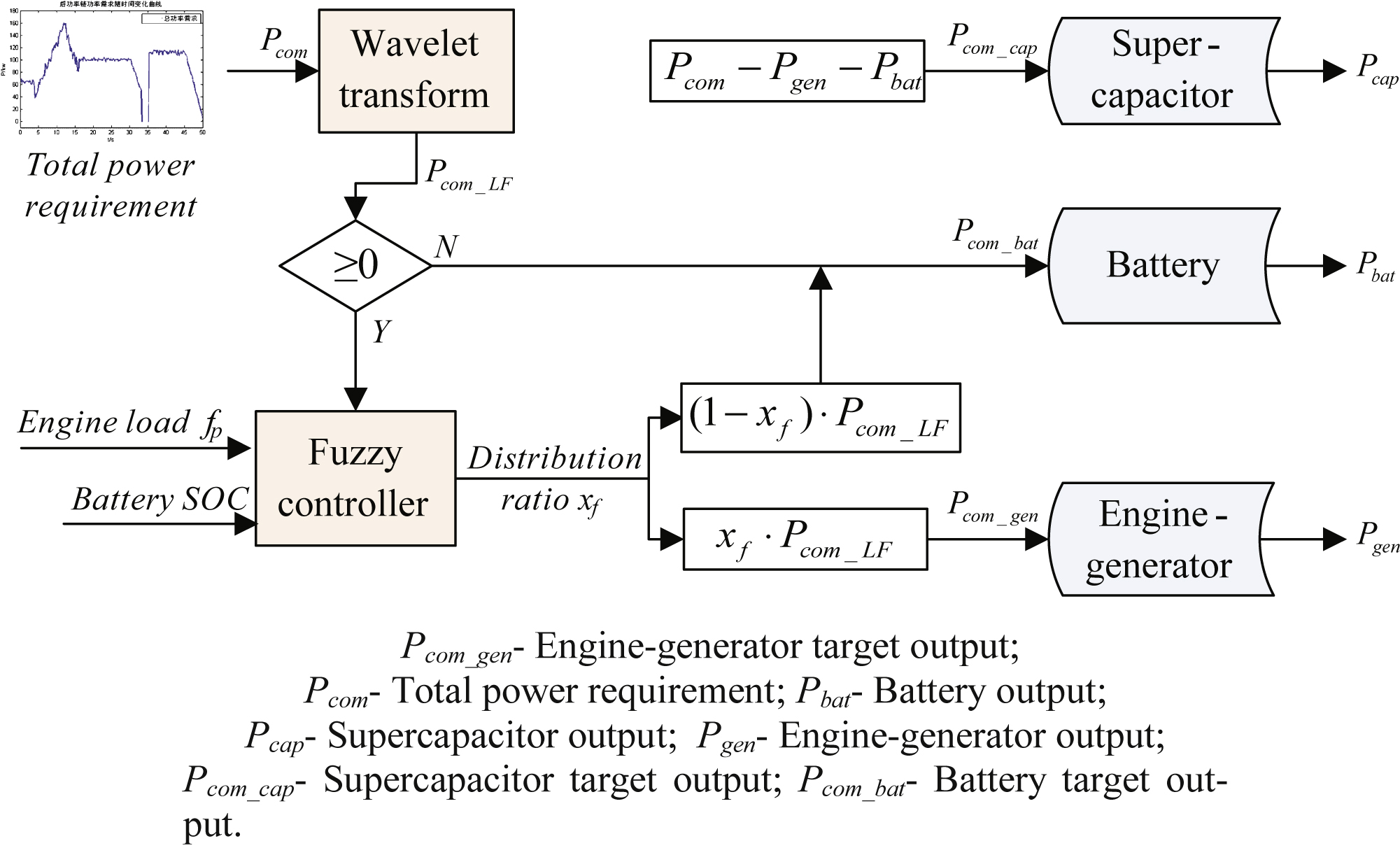
Fig.4
Block diagram of fuzzy control strategy.
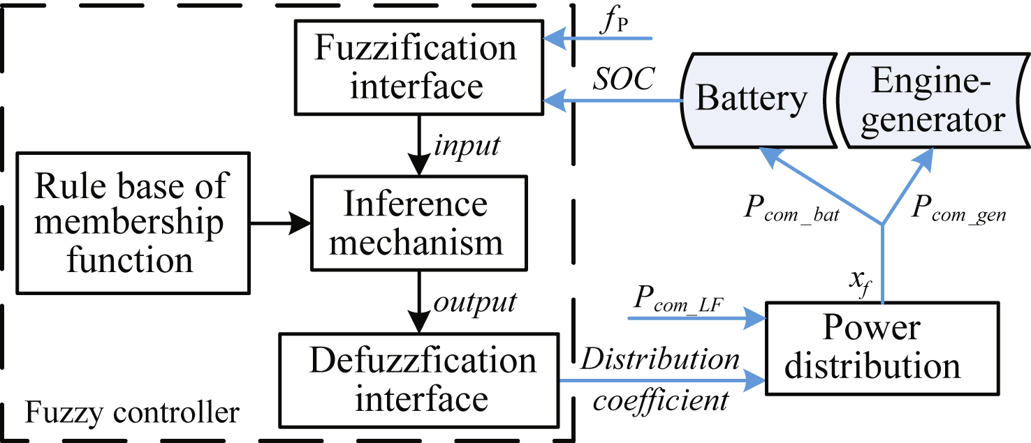
Fig.5
The membership function of fuzzy controller inputs.
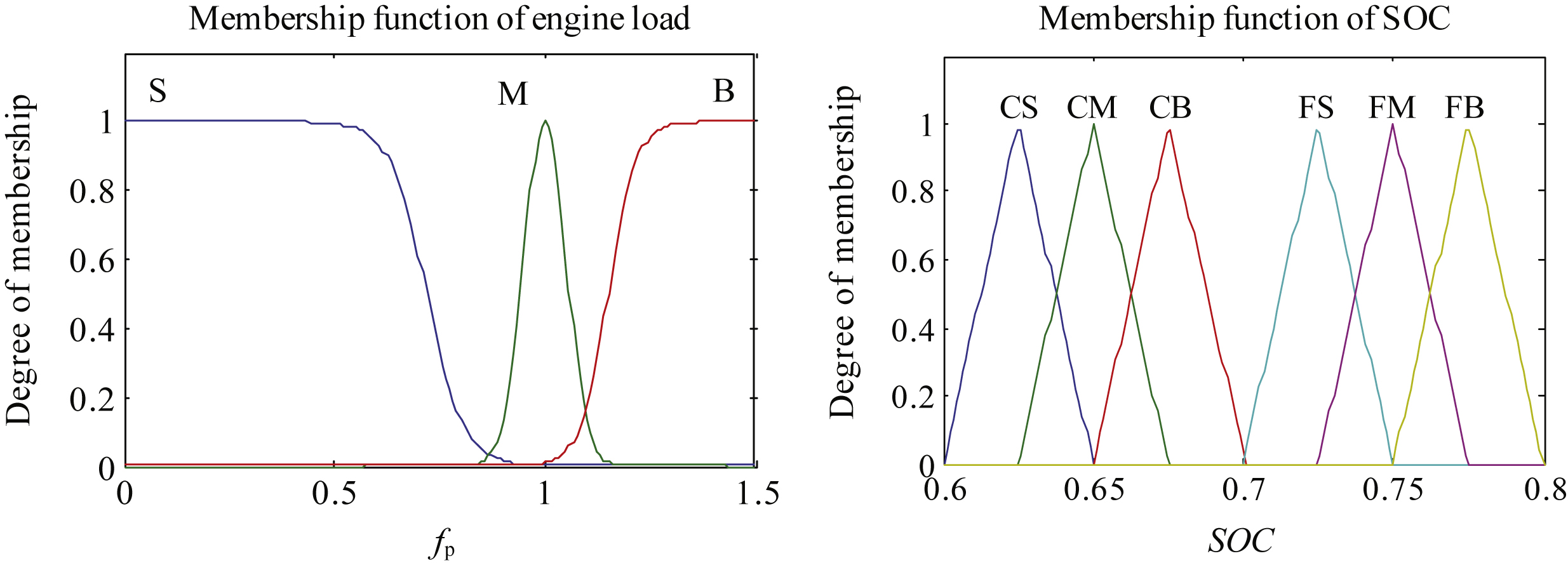
Fig.6
Flow chart of DEHPSO.
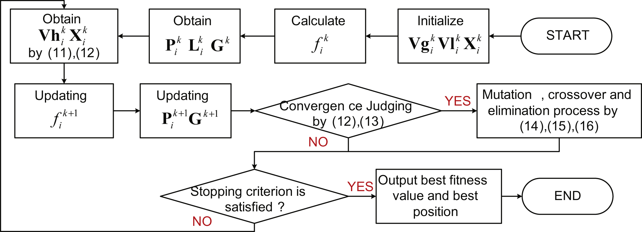
Fig.7
The optimized membership function of fuzzy controller inputs.
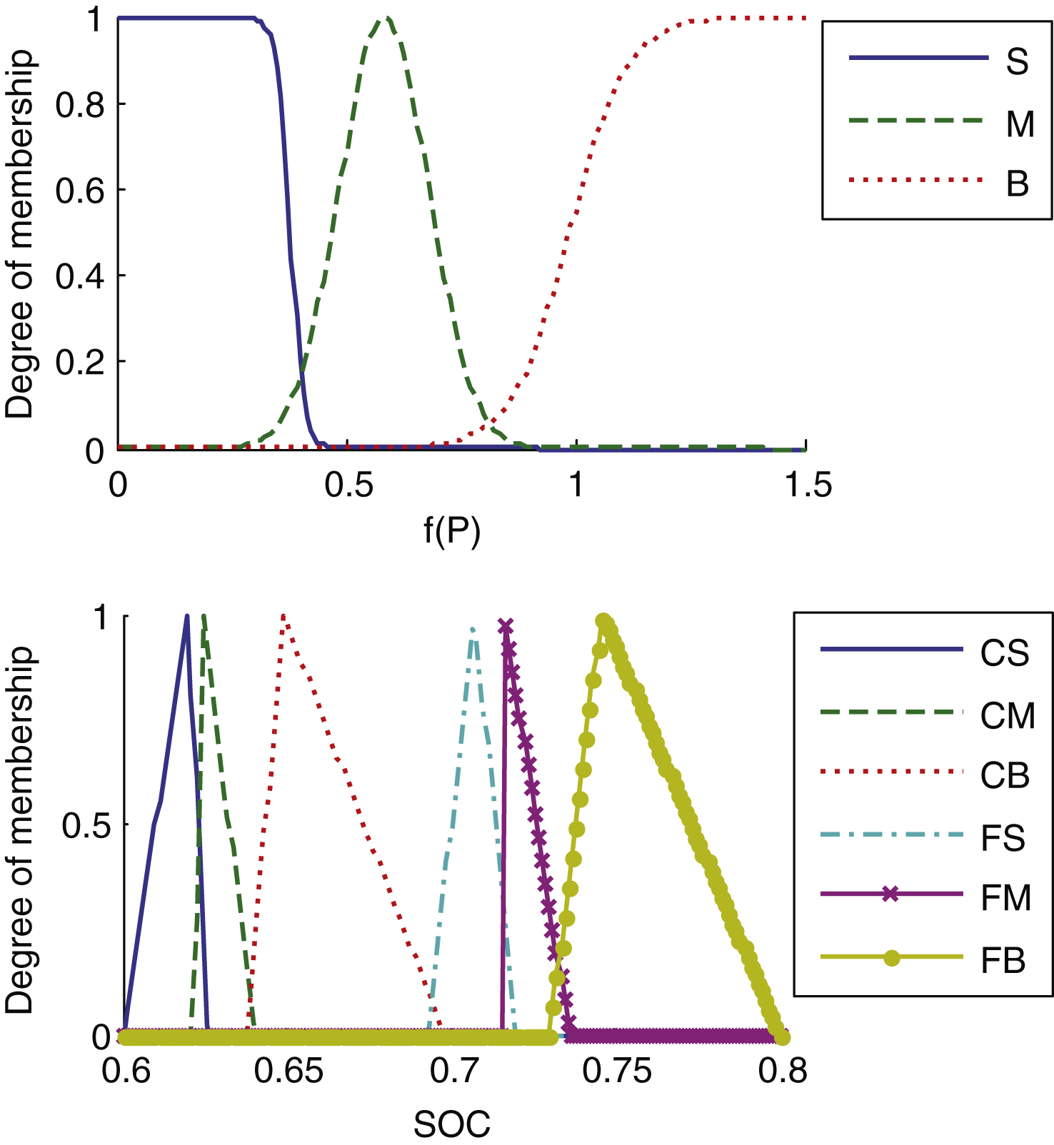
Fig.8
The decomposition and reconstruction processes of the 3-order Haar DWT.
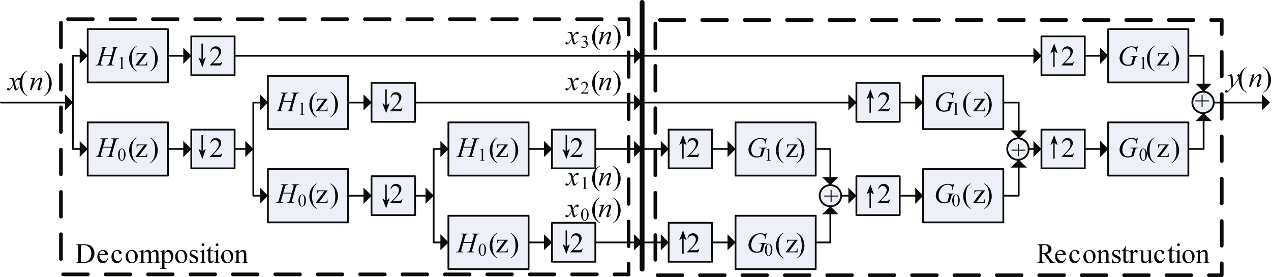
Fig.9
Models built in Matlab/Simulink.
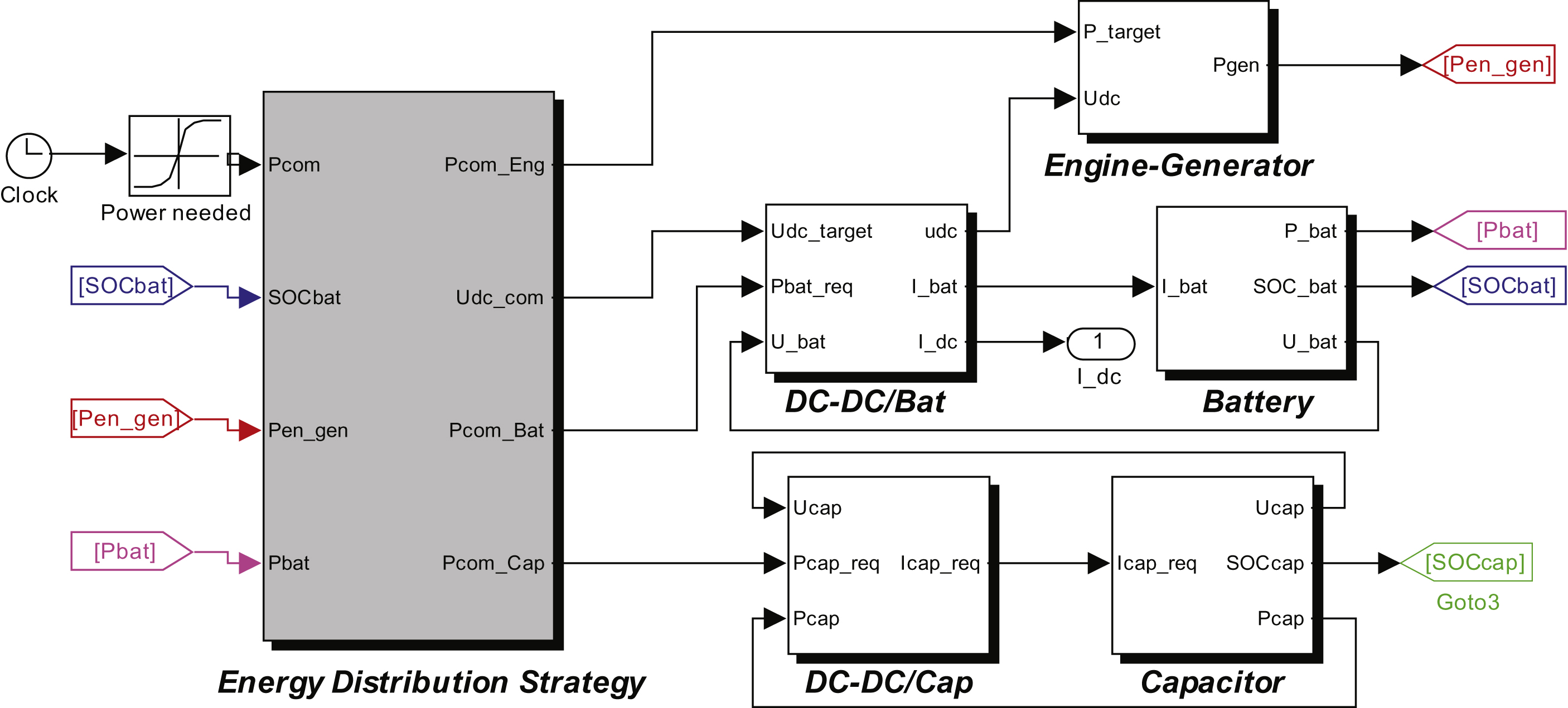
Fig.10
Equivalent circuit of the engine-generator set.
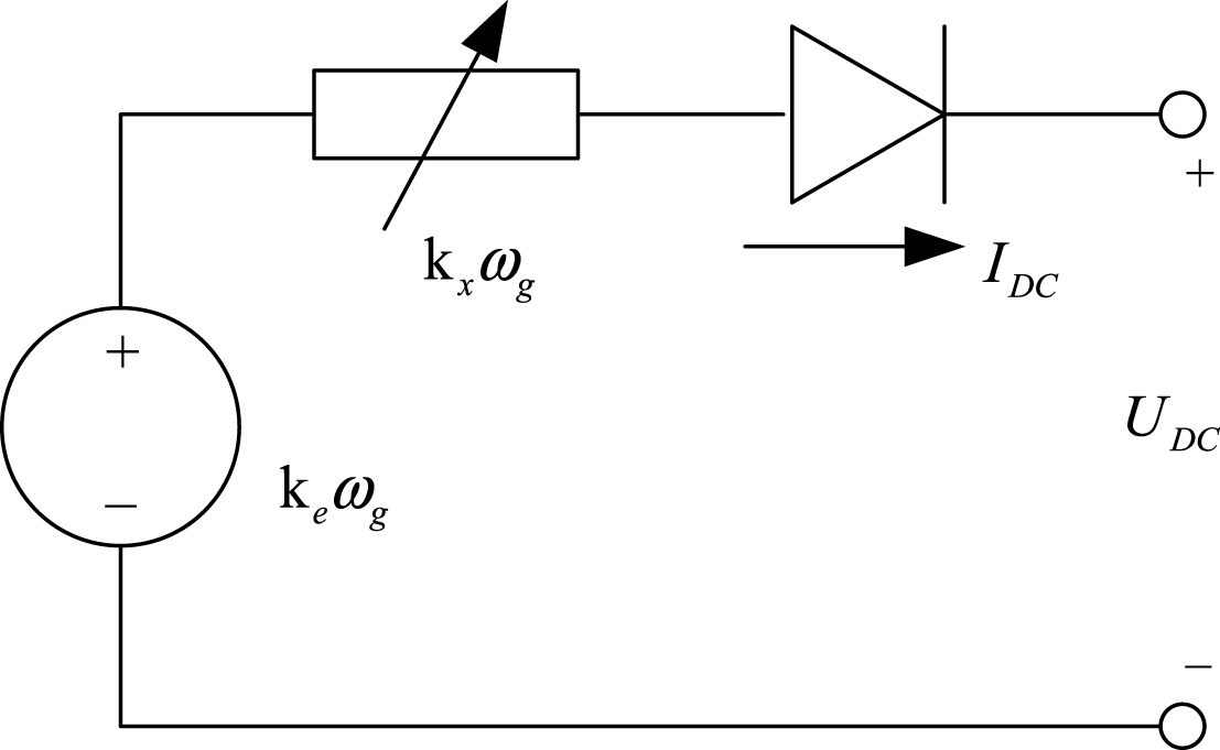
Fig.11
Equivalent circuit model of the battery pack.
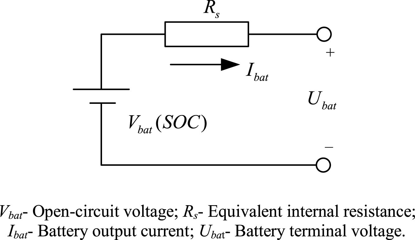
Fig.12
Equivalent RC model of the supercapacitor.
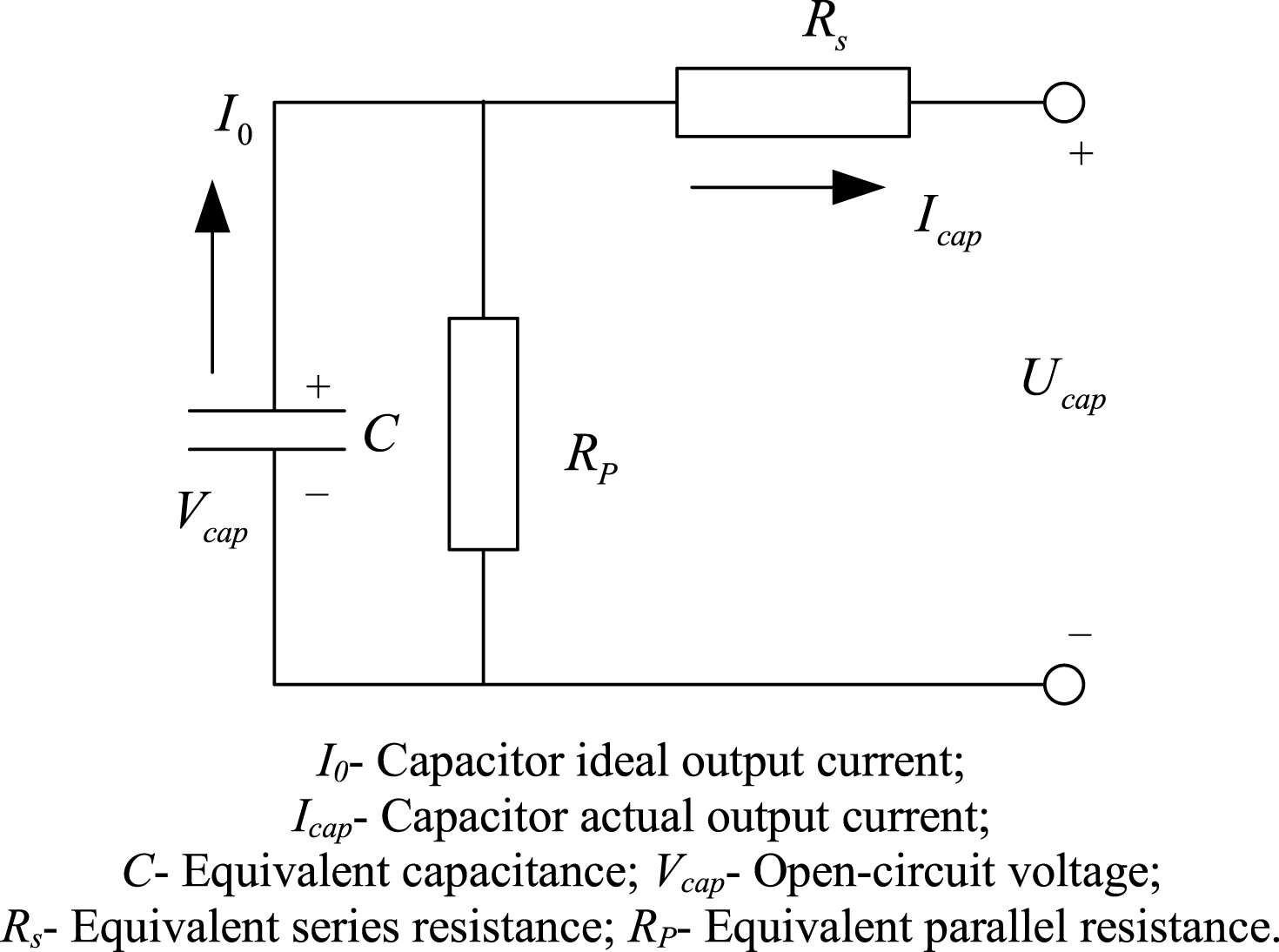
Fig.13
Structure of the driver-controller-based HILS.
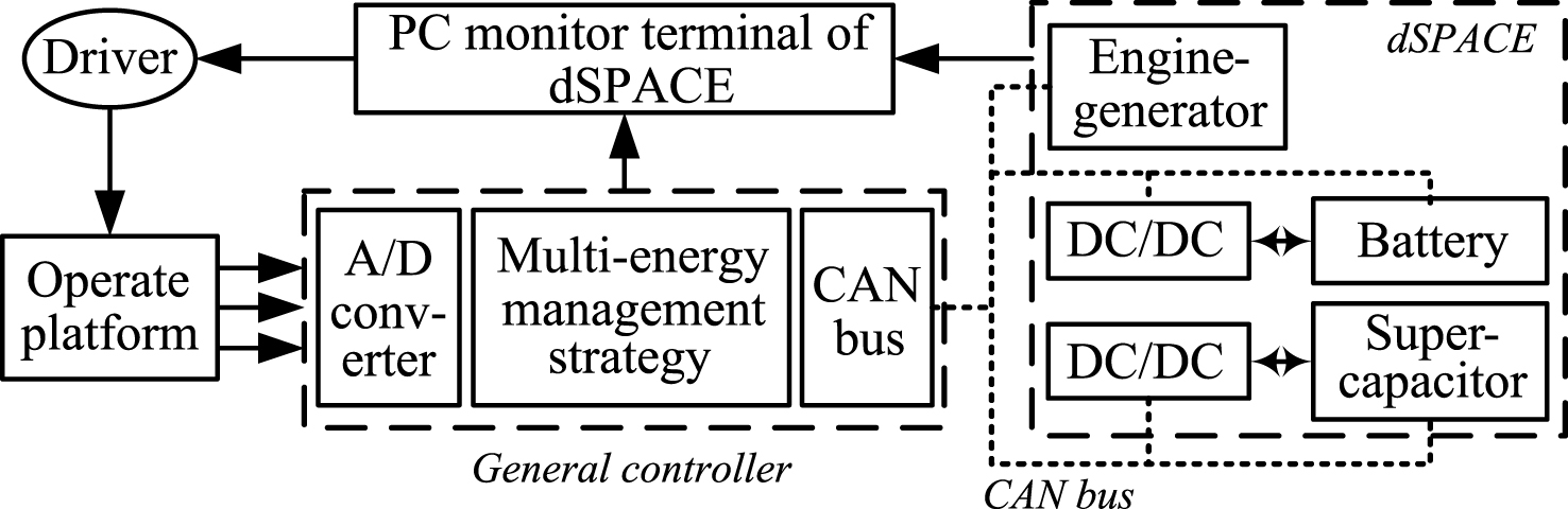
Fig.14
Hardware of HILS platform.
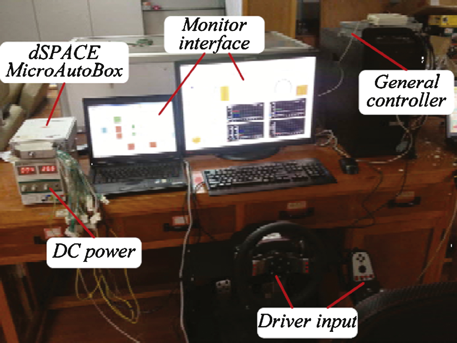
Fig.15
ControlDesk monitoring interface.
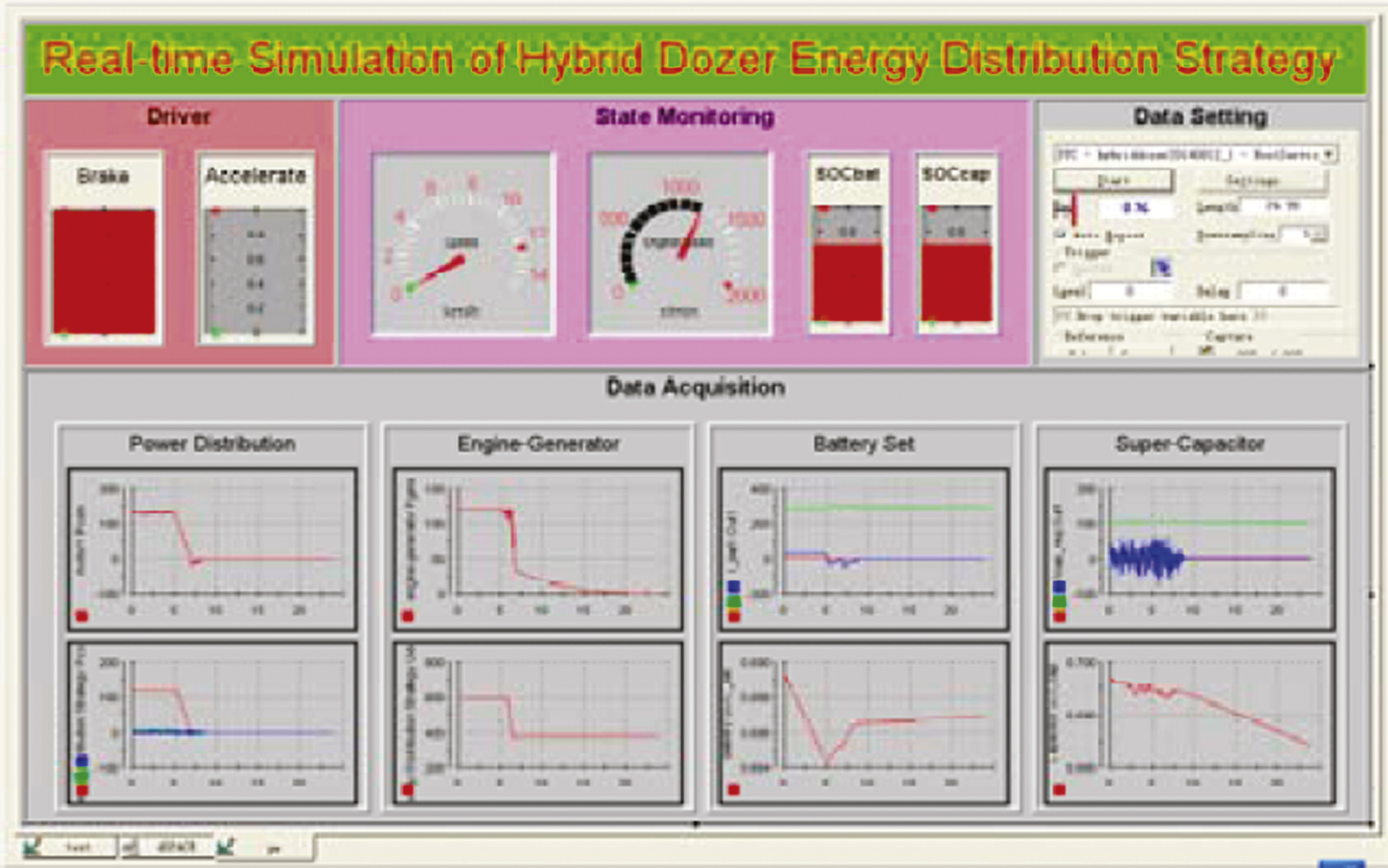
Fig.16
Power distribution result of the front power chain.
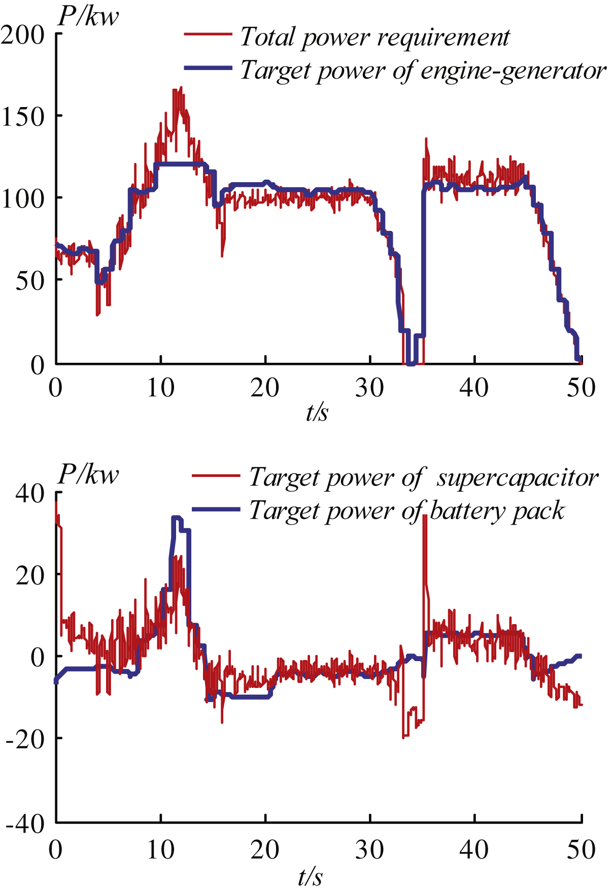
Fig.17
SOC changes of battery and supercapacitor.
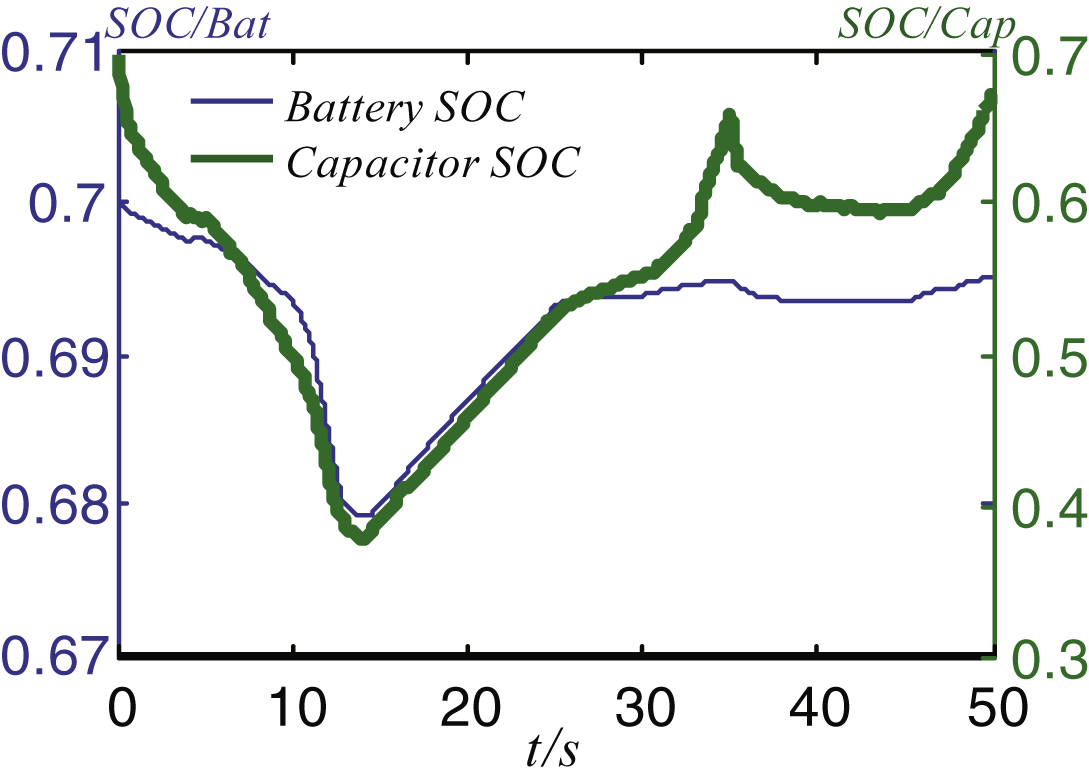
Fig.18
Current and voltage of the battery.
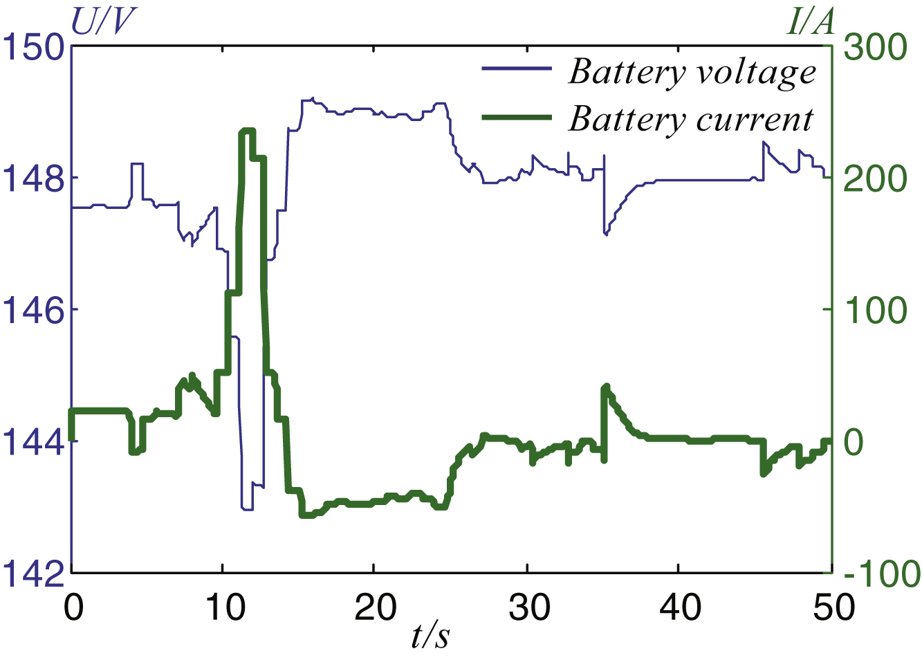
Fig.19
Current and voltage of the capacitor.
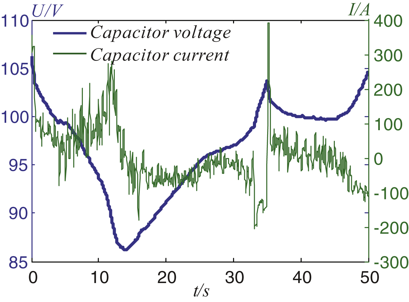
Table 1
The membership function of x f
| x f | VS | S | RS | MS | RB | B | VB |
| values | 0.8 | 0.85 | 0.9 | 0.95 | 1.05 | 1.1 | 1.2 |
Table 2
Rules based on Mamdani fuzzy control algorithm
| SOC f p | CS | CM | CB | FS | FM | FB |
| S | VB | VB | B | RB | M | RS |
| M | VB | VB | B | M | RS | S |
| B | VB | B | RB | RS | S | VS |
Table 3
The optimized membership function of x f
| x f | VS | S | RS | M | RB | B | VB |
| values | 0.8 | 0.8291 | 0.8736 | 0.8804 | 0.9398 | 1.0912 | 1.2 |


