
3D virtual visual plane design method based on ordered point sequence under the influence of COVID-19
Abstract
The transmission routes of novel coronavirus pneumonia include direct transmission, aerosol transmission and contact transmission. Therefore, the novel coronavirus pneumonia has been spread very quickly. This has a certain impact on the development of graphic design. Graphic design plays an important role in product design. However, the traditional aided design method is too complex, and it is difficult for designers to design works that meet their own needs. In the design of 3D virtual vision graphics, the distance calculation of time series is not accurate. This kind of error will bring some errors to the design of complex curved surface products. In order to measure the similarity of time series effectively, the calculation principle of Euclidean distance and dynamic bending distance is analyzed. Combined with the advantages of these two methods, a new distance calculation method based on morphological fitting is proposed. In this paper, through the research of ordered point sequence, the 3D virtual design method is used to improve the design effect, which has reference value for the design of works that meet the requirements of designers during the popularity of COVID-19.
1Introduction
The World Health Organization (WHO) said in June 19th that the new corona virus is still spreading rapidly around the world, and countries should prevent new epidemic peaks. According to WHO data, more than 150000 new cases were reported to WHO in 18 countries, nearly half of them from the Americas, and a large number of cases were also reported in South Asia and the Middle East.
The transmission routes of novel corona virus pneumonia are direct transmission, aerosol transmission and contact transmission. Therefore, novel corona virus pneumonia has been spread very quickly. This has a certain impact on the development of graphic design. Graphic design is an important stage of product design, which has a great impact on product performance, quality and market response, especially product innovation. Graphic design is an innovative activity. The traditional aided design method requires users to choose the set image template in many menus. It is not only complicated to operate, but also the designer is unable to design works that meet their own requirements, and the intention expression is not accurate [1, 2]. For this reason, this paper designs a new graphic design method based on 3D virtual vision technology, which realizes graphic design through 3D modeling of hand-painted works, with strong independence.
In addition, the distance calculation of time series is not accurate in the shape fitting of 3D virtual visual graphic design [3]. This kind of inaccuracy will bring some errors to the design of complex surface products. In order to effectively measure the similarity of time series, based on the analysis of the calculation principles of Euclidean distance and dynamic bending distance, combined with the advantages of these two measurement methods, a method of distance calculation of time series based on morphological fitting is proposed. The ordered point sequence is used to reduce the dimension of time series in sections, and the reduced dimension sequence is fitted with shape to calculate the distance between the sequences after shape fitting. The experimental results show that this method has the advantages of high accuracy and high efficiency.
2Graphic design method based on 3D virtual vision technology
2.1Development environment
To build a good 3D virtual model, we need to use appropriate technology and tools according to the characteristics of the target object [4–6]. This paper mainly uses VRML technology and 3DS MAX technology to build three-dimensional virtual model. The operating system is Windows 2000, VRML editor is VrmlPad2.0, Java editor is 3DS MAX 3.1 Chinese version, and VRML browser is ComsoPlayer 2.1 [7]. System environment configuration mainly includes Java program development environment configuration and server configuration. In the configuration of Java programming environment, it is relatively difficult for the operating system to query and edit files, and when the set command is used, the system must be reconfigured every time it is turned on, which wastes a lot of time. Therefore, the system property dialog box is used to SET the variable value. In the process of server configuration, the Tomact 4.1 server version is adopted because there is no server version in the operating system Windows 2000 [8].
2.2Acquisition and preprocessing of hand drawn strokes
This section mainly introduces the process of stroke acquisition and stroke preprocessing, which includes stroke denoising and stroke curve fitting.
2.2.1Obtaining hand drawn strokes
First of all, the process of obtaining hand drawn strokes is introduced: hand drawn with mouse, and a stroke is formed by the sequence of acquired ordered points. A stroke describes the ordered sequence of several points R [9–13]:
(1)
Where qi is the point in the display. Set the speed of each point, that is,
2.2.2Denoising of hand drawn strokes
When using mouse to draw, hand jitter will produce noise. In addition, when the input stroke information is transformed into the coordinate points on the display screen, there will also be noise due to certain errors. The lower the resolution of the display, the greater the error. In this section, smooth denoising method is used for denoising.
The basic idea of smooth denoising is to correct the current point value with the neighboring point value. If Equation (1) is smoothed, there are:
(2)
Among them:
(3)
Where: wj is used to describe the weight value of qj; N is a positive integer, and the larger its value is, the smoother the obtained hand drawn strokes are.
2.2.3Curve fitting of hand drawn strokes
This section uses quadratic B-spline curve to fit hand drawn strokes. B-spline curve controls the curve shape through multiple control points. The formula is described as follows:
(4)
In the formula, the initial wmin ⩽ w ⩽ wmax; 2 ⩽ l ⩽ m + 1; gn is used to describe the input m + 1 control points; fn,l (w) is used to describe the B-spline mixed basis function.
It can be seen from Equation (4) that the point G(w) on the fitting curve is mainly determined by the control point gn. The inverse subdivision method is used to reduce the noise of B-spline to ensure that it has the same control points.
The inverse subdivision method can divide the data into rough part and detail part. The detail part is mainly composed of the noise which can be removed, and the rough part can be regarded as the control point gn which needs to fit the curve.
If a0, a1, a2, ⋯ , am are used to represent the points before the inverse subdivision, and b0, b1, b2, ⋯ , bm are used to represent the points of the rough part after the inverse subdivision, there are:
(5)
Where A = [a0, a1, a2, ·· · , am] T
and
According to Equation (5), n becomes almost half of m after one subdivision. Then the final point set G is the control point to fit the curve.
Because the strokes have been sampled and smoothed, only one inverse subdivision of point set G is needed to obtain the control points, so that the fitting curve consistent with the original input can be obtained.
By fitting the curve, the stroke points are evenly distributed and the points can be adjusted adaptively, which makes the 3D model grid of graphic design easy to manage and operate.
2.33D virtual modeling of hand drawn strokes
After obtaining and preprocessing the hand-painted strokes, the 3D virtual modeling is carried out to realize the graphic design. For multi stroke input, the input stroke information is saved by quadruple H (αi, βi, χi, δi) All elements are saved by class library. Among them, α is used to describe the recognized stroke information, β is used to describe the spatial position, χ is used to describe the topological information of the input stroke, and δ is used to describe the stroke features. The stroke information obtained after the processing is described by Ui, and the constraints that meet the design conditions are described by Di. The spatial position and topological information of strokes are mainly obtained through the stroke recognition process. Save the information of the strokes designed by the designer, find out the plane angle of different strokes, and get the space position between strokes. The three-dimensional modeling process of designer’s hand-painted works is as follows:
1) The input information H (αi, βi, χi, δi) is initialized;
2) Identify the strokes drawn by the designer:H (αi, βi, χi, δi) → Ui (Di) if it is a single stroke, output the result; otherwise, continue to the next step;
3) Reasoning on the constraints of combination conditions of design works:
4) Judge whether Um belongs to the known model, if so, insert it into the model to realize 3D model construction; otherwise, repeat step 1).
In the above process, the purpose of step 2) is to identify the input hand drawn strokes, form the basic image information U, and judge whether the modeling process is single stroke or multi stroke through interactive processing. If it is a single stroke, the result will be displayed; otherwise, continue to the next step, and achieve the matching through constraint solving, so as to obtain the 3D model U.
2.4Realistic rendering of graphic design works
After the establishment of three-dimensional model of graphic design work, it is necessary to render its reality. In this section, color rendering is used to improve the visual effect. Color rendering can make the 3D modeling effect colorful. When color rendering, you need to set color array for all vertices, and the vertex color is:
(6)
Where: boc is used to describe the bottom color; toc is used to describe the top color; k [i] [j] is used to count the jth color value of the ith layer.
3Euclidean distance and dynamic bending distance calculation
GEMINI framework is proposed to solve the modeling method of time series, and becomes the main framework of time series. Generally, time series with length of N can be regarded as a point in N-dimensional space, and these points can be indexed by multidimensional indexing mechanisms such as R-tree and K-D tree. However, the existing methods are generally only effective for points in 8–10 dimensional space, and the actual time series data are often It will be far beyond this limit, resulting in a sharp decline in performance, leading to the “dimension disaster” problem. A large number of distance measurement studies based on GEMINI framework use the European distance and dynamic bending distance (DTW).
Define 1 time series. Time series T = t1, t2, … tn, is a series of orderly arranged observation values, which can be values or vectors; the observation value of T is defined as the sequence point of T, ti represents the ith sequence point of T, i is the index number of ti; the number of sequence points of T is defined as the length of sequence T, which is recorded as Tlen = n; it is usually a simple description, referred to as time series.
3.1Euclidean distance calculation
Euclidean distance is a widely used similarity measure of time series, which was widely used in the early stage of time series similarity research. Its calculation formula is
(7)
The experimental sequence is given:
Test- X = 17.223 5,21.7889,23.8187,
28.0992, 29.2357, 32.1344, 43.1505,
44.4259, 38.6312, 32.2653, 34.8402,
25.9655, 23.7696, 18.9009, 12.8192,
20.8196, 29.5038, 35.8682, 39.2315,
46.9979, 44.0014, 37.8552, 41.0403,
29.2411, 25.4182, 19.9570, 11.8583,
22.3583, 21.6046, 31.2824, 34.6503,
44.6238, 38.3330, 47.4585, 40.0818,
29.0800, 27.5489, 17.7724, 16.1624,
22.6897;
Test-Y = 15.6932,22.6271,35.4492,
41.4701, 45.5868, 42.5029, 33.1578,
33.9853, 19.0391, 14.6295, 15.2926,
24.0683, 24.7247, 37.9322, 47.5312,
47.9608,38.2376,33.4948,31.8874
17.4009, 14.9492, 15.0030, 23.2439,
26.7731, 34.7717, 40.3571, 38.0118,
39.9174, 35.4881, 24.5046, 21.6087,
14.4941, 14.8137, 24.6532, 35.3538,
40.3240, 47.4154, 39.0893, 39.7996,
24.0185.
Figure 1 shows the effect diagram of Euclidean distance calculation between Test_X (time series 1) and Test_Y (time series 2).
Fig. 1
Calculation effect of European distance.
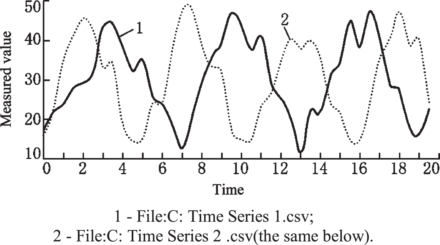
The Euclidean distance requires that the length of the sequence to be calculated is equal, which has the advantages of intuitionistic and simple calculation. For the sequence of length n, the time complexity is O (n), but it calculates the sequence point-to-point according to the time axis, and has the disadvantage of low calculation accuracy for the non-constant sensitivity of the sequence points, such as dislocation, displacement and mutation.
3.2Calculation of dynamic bending distance
Dynamic bending distance is first applied successfully in the field of speech digital processing, and then it is introduced into time series data mining
For time series X = x1, x2, ·· · , xm and Y = y1, y2, ·· · yn dynamic bending distance can be recursively defined as
Where: Rest (X) = x2, x3, ·· · , xm ; Rest (Y) = y2, y3, ·· · , yn The calculation results of dynamic bending distance between Test_X and Test_Y are shown in Fig. 2.
Fig. 2
The effect diagram of DTW distance calculation.
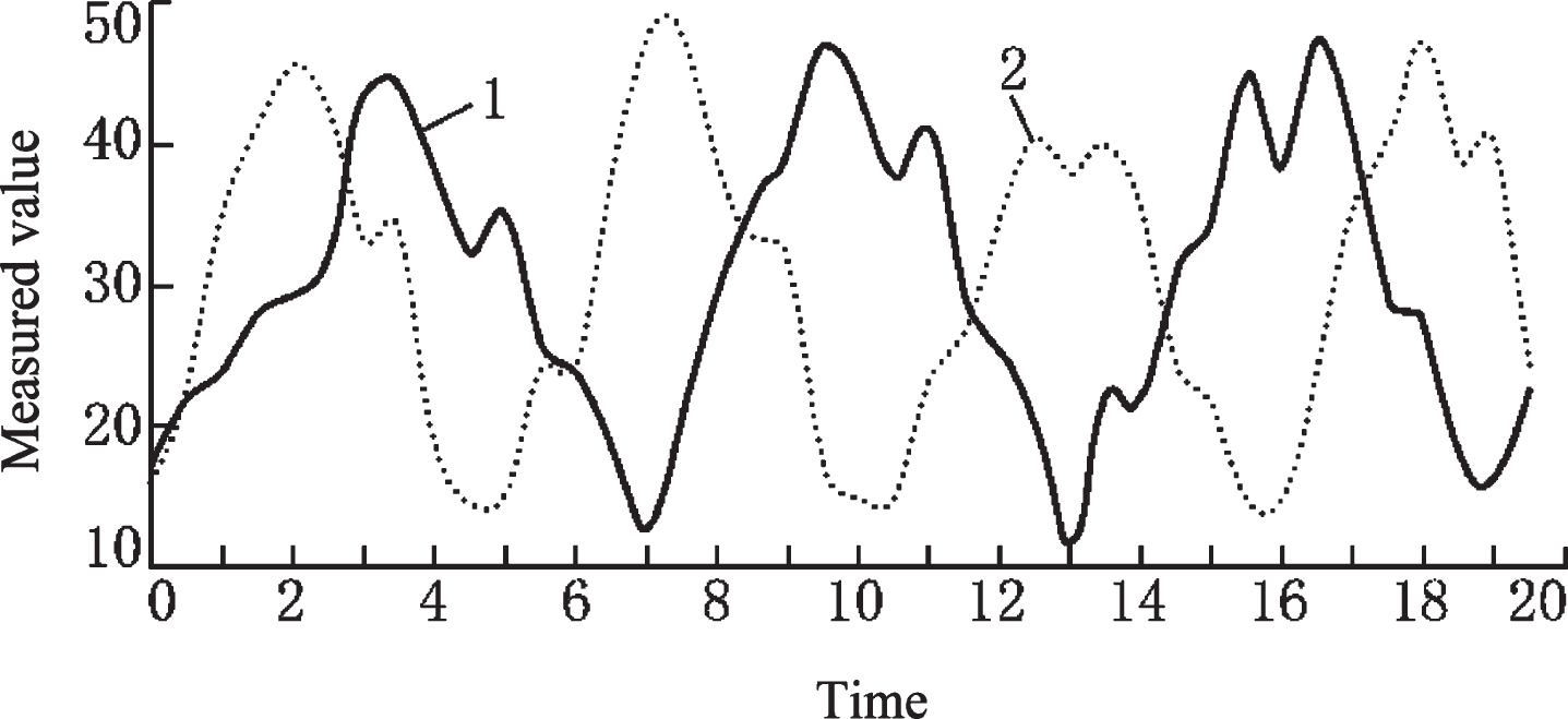
The essence of the dynamic bending distance calculation method is to find the best fitting shape of the sequence through the displacement of the sequence point on the time axis, and calculate the sequence distance after the shape fitting. It has the advantages of high accuracy in calculation, but its calculation time complexity is very high. For the sequence with length of m and n respectively, the time complexity of O(mn) is needed to accurately calculate the dynamic bending distance.
4Distance calculation based on shape fitting
4.1Calculation principle
The time complexity of the Euclidean distance calculation method is O(n), which has a high calculation efficiency, but the calculation accuracy is very low and the leak rate is very high; the calculation accuracy of the dynamic bending distance is very high, but its calculation time complexity is O(mn), which cannot be applied to the system with high real-time requirements; the defects of the two methods limit their application in practice.
The reason why the accuracy of the Euclidean distance calculation is not high is that the method carries out strict point-to-point calculation for the sequence according to the time axis without considering whether the overall shape of the sequence corresponds to each other; the calculation of the dynamic bending distance allows the sequence points to move backward on the time axis, and the calculation result is the result of the best fitting of the overall shape of the sequence, and the calculation result of the dynamic bending distance meets the overall calculation The disadvantage of the Euclidean distance calculation method is that it does not consider whether the overall shape of the time series fits, The solution is to fit the shape of the sequence. The disadvantage of dynamic bending distance calculation is the length of the sequence, and there is the problem of dimension disaster. In order to solve the problem of dimension disaster, we usually reduce the dimension of the sequence, Keogh and others noticed that most of the sequences can be processed in the average section, and then use the mean value of the data in the section to represent the whole section. Based on this, we put forward the sliding method the sequence representation method of PAA is simple, easy to realize, easy to understand and can effectively reduce dimensions.
In this study, the two calculation methods of Euclidean distance and dynamic bending distance are combined to eliminate the unfavorable factors that affect the application of the two methods, and the advantages of the two methods are brought into play. A time series distance calculation method based on shape fitting is proposed. The method to eliminate the unfavorable factors is to carry out sequence reduction and shape fitting.
4.2Computing method
The distance calculation method of time series based on morphological fitting is shown in algorithm 1.
Algorithm 1: The distance calculation of time series based on shape fitting.
Enter X = x1, x2, …, xm // a time series of length m; Y = y1, y2, …, yn // time series of length n; w (1 ⩽ w ⩽ min(m, n))//PAA sliding window size.
Handle
Xs,l,δ = PAA (X, w)//segmentation sequence X;
Ys,lδ = PAA (Y, w)//segmentation sequence Y;
For k = 1 to
〈i, j 〉 = PathXδ,Yδ [k]//read fit path relationship;
End Loop;
return
It is worth noting that when PAA method segments X and y, The length of the sequence segment at the end of the 2-sequence may not be equal to the size of the sliding window, which results in the unequal length of the sequence participating in the Euclidean distance calculation. The Euclidean distance calculation requires the equal length of the 2-sequence participating in the calculation. Therefore, the Euclidean distance calculation method must be improved so that it can calculate the distance of the unequal sequence. The improved method is to move the sequence points at the end of the short sequence along the When the time axis moves backward, calculate the distance between it and the sequence point whose length exceeds the length. The improved Euclidean distance calculation method is shown in algorithm 2.
Algorithm 2: The calculating Euclidean distance of unequal length 2 series.
Input X = x1, x2, …, xm //time series of length m; Y = y1, y2, …, yn //time series of length n.
Handle
x-s = 1;x-e=m//X sequence pointer initialization;
y-s = 1;y-e=n//Y lnitialization of sequence pointer;
D = 0//Initialize distance value;
While(not(x-s = =x-s and y-s = =y-e)).
Loop;
d = d + (xx-s - yy-s) 2//calculate point distance;
if (x - s < x - e);
x - s = x - s + 1//move data pointer of X series;
if (y - s < y - e);
y - s = y - s + 1//move data pointer of Y series;
End Loop;
return d//returns the result of distance calculation. Because it is called by algorithm 1, the square root is not processed.
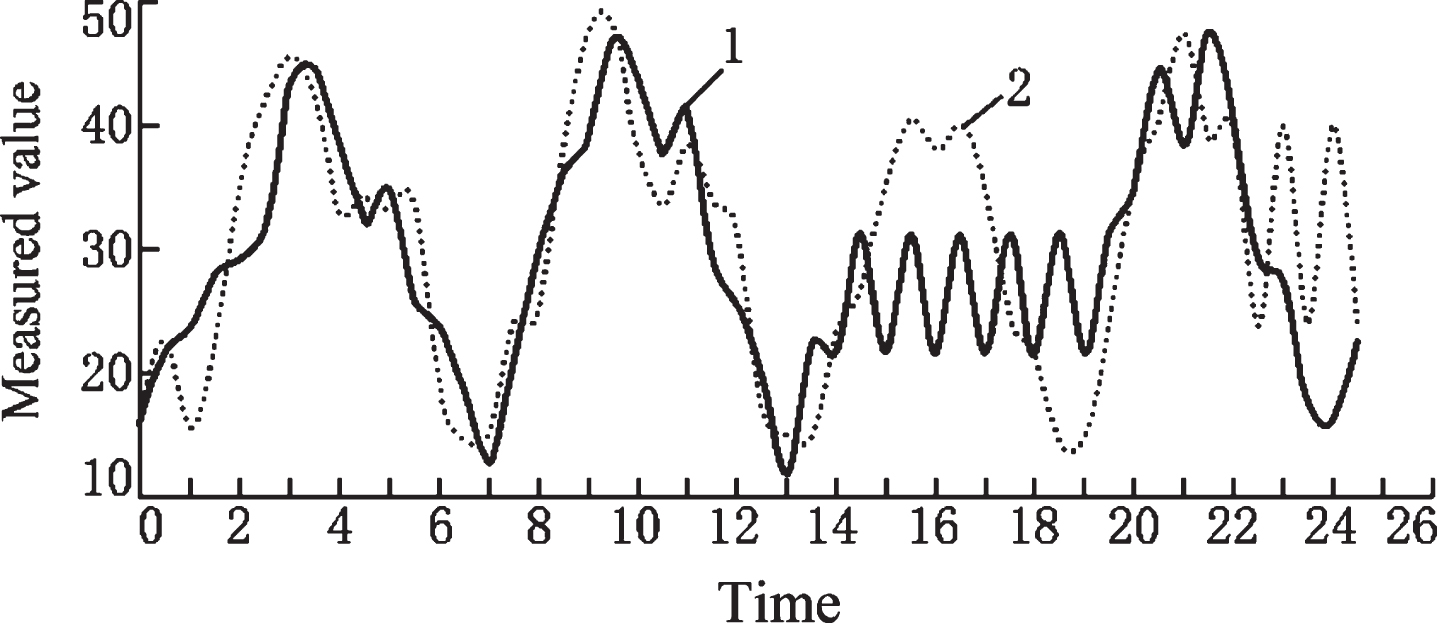
The results of the shape fitting distance calculation of Test_X and Test_Y are shown in Fig. 3.
Fig. 3
The effect diagram of shape fitting distance calculation.
5Analysis of experimental results
5.1Application test of this method
In this section, the method of this paper is used to design the bamboo baskets and stems and leaves. First, the designers draw them by hand, and then carry out three-dimensional virtual modeling. The sketch of bamboo basket is shown in Fig. 4(a) and the result of 3D virtual modeling is shown in Fig. 4(b). The stem leaf sketch is shown in Fig. 5(a), and the 3D virtual modeling results are shown in Fig. 5(b).
Fig. 4
Bamboo basket design results with the proposed method.
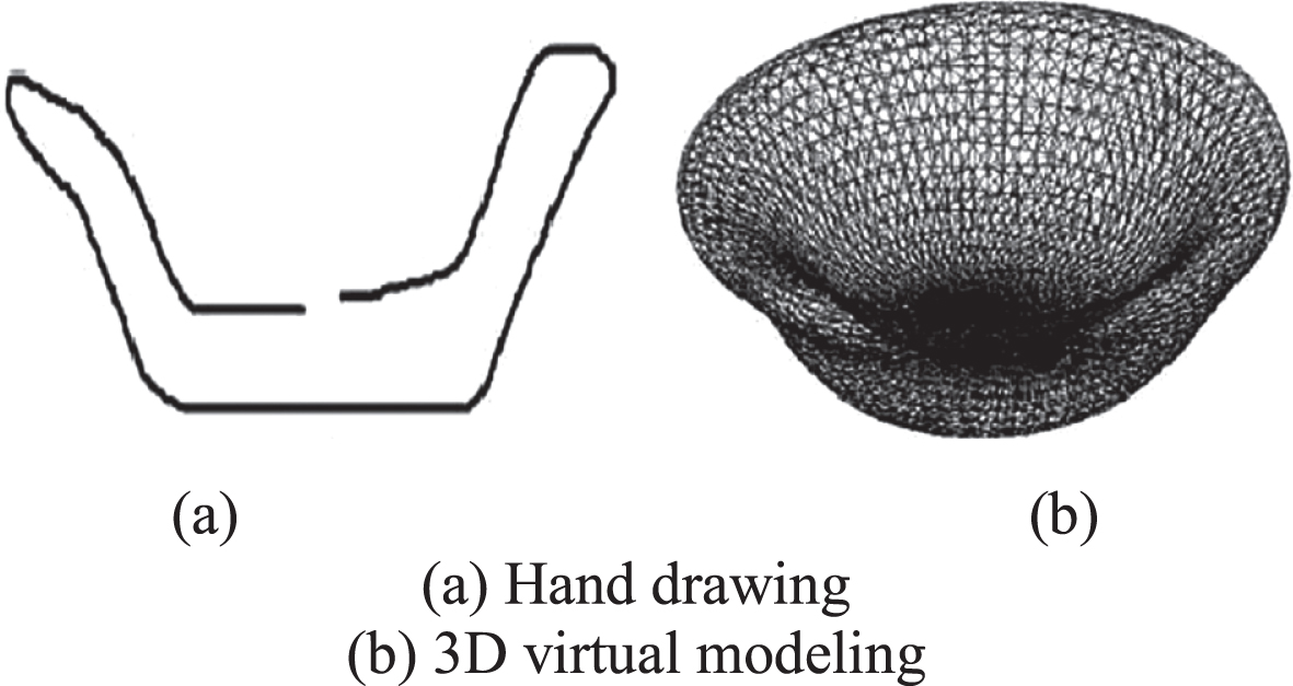
Fig. 5
Stem leaf design results with the proposed method.
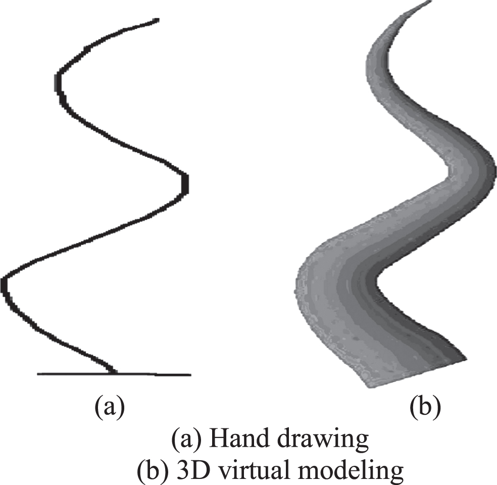
According to the analysis of Figs. 4 and 5, the method in this paper can effectively realize 3D virtual modeling based on hand-painted strokes, making the obtained 3D renderings more realistic, and helping designers to show the real design intent.
5.2Fuzzy comprehensive evaluation results
Graphic design is an uncertain process, so this section uses fuzzy evaluation method to evaluate the graphic design method. The method of fuzzy evaluation applies fuzzy mathematics to psychology and deals with the problem of fuzzy evaluation quantitatively. When evaluating the graphic design method, it is not sure what kind of evaluation grade it belongs to. The evaluators usually tend to a certain evaluation grade, but other evaluation grades can also, which makes it impossible to judge the evaluation results accurately. This section divides the evaluation grades based on all possible psychological reactions, such as very satisfied, relatively satisfied, generally satisfied, unsatisfied, very unsatisfied. All evaluators are required to evaluate various grades, as shown in Table 1. The detailed evaluation process is as follows: the subjects are asked to select the most satisfying grade category in the evaluation table, and set the corresponding confidence level. Compare the conformity degree of the evaluation grades on both sides of the most satisfying grade, give the confidence grade, and then evaluate the remaining grades. If the subjects think that the actual feelings are consistent with the leftmost level, they will be evaluated from left to right; otherwise, they will be evaluated from right to left.
Table 1
Scoring form
| Compliance | Very dissatisfied | Dissatisfied | General satisfaction | Satisfied | Very satisfied | |
| (1) | (2) | (3) | (2) | (5) | ||
| Accord with | Complete (6) | √ | ||||
| Conform to basic (5) | √ | |||||
| A little (2) | √ | |||||
| Inconformity | A little (2) | √ | ||||
| Inconformity with basic (1) | √ | |||||
| Full (0) | ||||||
Through fuzzy evaluation, the result is a set of vectors, so it can provide more information and master the psychological state and evaluation process of the subjects. In order to prevent the negative value of the evaluation value, the weight of category is generally 1–5, the weight of confidence is generally 0–2, 4–6, and then the final evaluation result is obtained through weighted average point estimation. The calculation formula is:
(8)
Where: wi is used to describe category weight; yi is used to describe confidence weight.
In order to verify the effectiveness of this method, the compressed sensing method and machine vision method are compared. Let 50 designers respectively use the methods in this paper, compressed perception method and machine vision method for graphic design, and evaluate the three design methods through the above-mentioned fuzzy evaluation process, and take the evaluation mean value of 50 designers as the final result, as shown in Table 2.
Table 2
Comparison of evaluation results with three methods
| Evaluating indicator | Methods of this paper | Compressed sensing method | Machine vision method |
| Very dissatisfied cases/case | 0 | 3 | 4 |
| Cases of dissatisfaction | 2 | 6 | 5 |
| Cases of general satisfaction | 2 | 12 | 15 |
| More satisfactory cases/case | 12 | 19 | 20 |
| Satisfied cases/case | 34 | 10 | 6 |
| Average score/point | 4.56 | 3.54 | 3.38 |
According to Table 2, no user is dissatisfied with this method, only 2 users are dissatisfied with this method, and other users are satisfied with this method, of which 34 users are satisfied with this method. But 9 users are not satisfied with the compressed sensing method and machine vision method, only 10 users are satisfied with the compressed sensing method, and 6 users are satisfied with the machine vision method, which is far worse than the method in this paper. And the average user evaluation score of this method is 4.56, which is significantly higher than 3.54 of the compressed sensing method and 3.38 of the machine vision method. It shows that this method meets the designer’s requirements more and verifies the effectiveness of this method.
6Conclusions
The novel coronavirus pneumonia has been spread by local authorities. This has a certain impact on the development of graphic design. A graphic design method based on 3D virtual vision technology is proposed. The development environment is given, and the acquisition and preprocessing process of hand drawn strokes are introduced. On this basis, 3D virtual modeling and color rendering of hand drawn strokes are carried out. The experimental results show that the proposed method can meet the designer’s requirements and help the designer to show the real design intention during the popularity of COVID-19.
Acknowledgments
The study was supported by “Research on cultural identity of Silk Road documentary” (Humanities and Social) Sciences project of the Ministry of Education. Grant No. 18YJA760080.
References
[1] | Vingrys A.J. , Maddocks J.D. , Hely C.P. , et al., Color recognition and discrimination under full-moon light, Applied Optics 33: (21) ((1994) ), 4741. |
[2] | Berens C. , Visual Acuity and Color Recognition Test for Children, American Journal of Ophthalmology 46: (2) ((1958) ), 219. |
[3] | Zimmer J. and Knipp D. , Amorphous silicon-based unipolar detector for color recognition, IEEE Transactions on Electron Devices 46: (5) ((1999) ), 884–891. |
[4] | Caulfield H.J. and Mueller P.F. , Direct Optical Computation Of Linear Discriminants For Color Recognition, Optical Engineering 23: (1) ((1984) ), 16–19. |
[5] | Bombardier V. and Schmitt R. , Fuzzy rule classifier: Capability for generalization in wood color recognition, Engineering Applications of Artificial Intelligence 23: (6) ((2010) ), 978–988. |
[6] | Lee S.D. , Tzeng C.Y. , Kehr Y.Z. , et al., Autopilot System Based on Color Recognition Algorithm and Internal Model Control Scheme for Controlling Approaching Maneuvers of a Small Boat, IEEE Journal of Oceanic Engineering 35: (2) ((2010) ), 376–387. |
[7] | Chen P. , Bai X. and Liu W. , Vehicle Color Recognition on Urban Road by Feature Context, Intelligent Transportation Systems, IEEE Transactions on 15: (5) ((2014) ), 2340–2346. |
[8] | Benítez-Díaz D. , Modular architecture for custom-built systems oriented to real-time computer vision: Application to color recognition, Journal of Systems Architecture 42: (9-10) ((1997) ), 709–723. |
[9] | Nakamura K. , Okajima O. , Nishio Y. , et al., New Color Vision Tests to Evaluate Faulty Color Recognition, Japanese Journal of Ophthalmology 46: (6) ((2002) ), 601–606. |
[10] | Cheong C. , Bowman G. and Han T.D. , Unsupervised clustering approaches to color classification for color-based image code recognition, Applied Optics 47: (13) ((2008) ), 2326–2345. |
[11] | Paschos G. , Fast color texture recognition using chromaticity moments, Pattern Recognition Letters 21: (9) ((2000) ), 837–841. |
[12] | Zhang J. , Pan R. , Gao W. , et al., Automatic recognition of the color effect of yarn-dyed fabric by the smallest repeat unit recognition algorithm, Textile Research Journal 85: (4) ((2015) ), 432–446. |
[13] | Wang Y.G. , Yang J. , Zhou Y. , et al., Region partition and feature matching based color recognition of tongue image, Pattern Recognition Letters 28: (1) ((2007) ), 11–19. |


